a new (old) #59?

1234567

1234567
Re: Intermediate tenders

|
Re: Intermediate tenders
|
|

Re: Intermediate tenders
|
Administrator
|
Re: Intermediate tenders
|
|

Re: Intermediate tenders
|
|

Re: Intermediate tenders
|
|
Re: Intermediate tenders
|
|
Re: Intermediate tenders
|
|
Re: Intermediate tenders
|
|
Re: Intermediate tenders
|
|
Re: Intermediate tenders
|
|
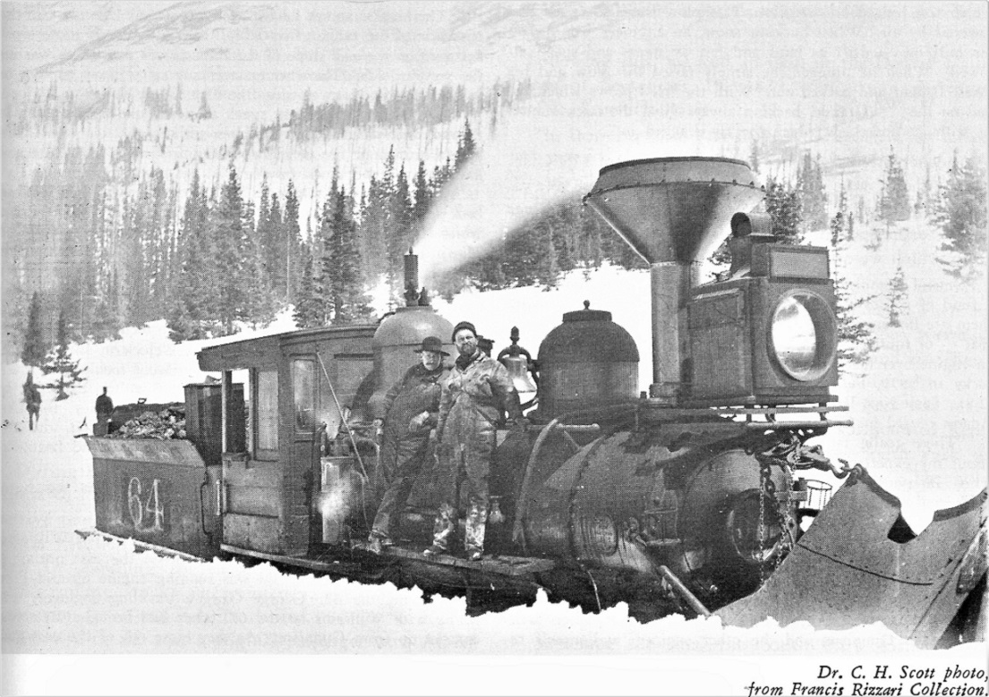
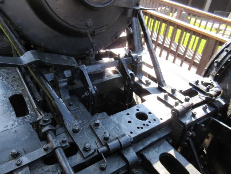
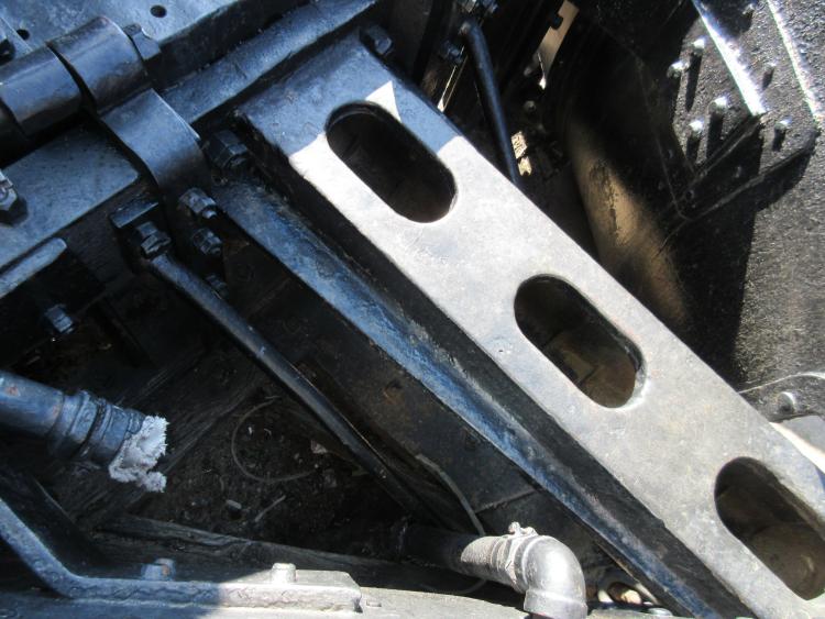
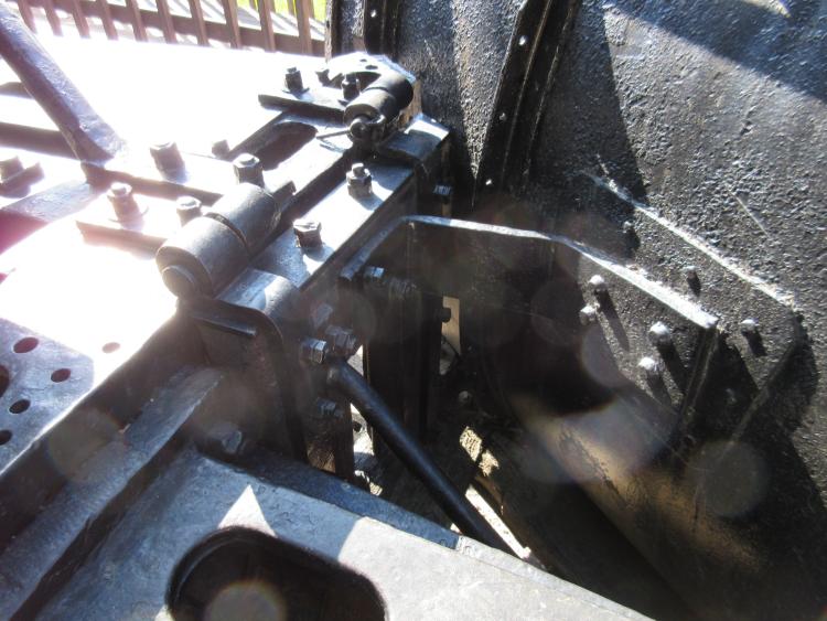
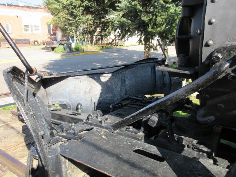
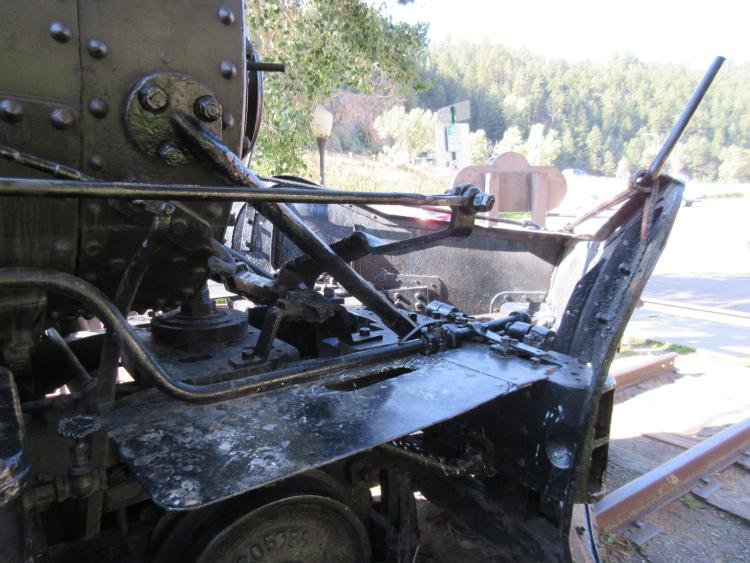
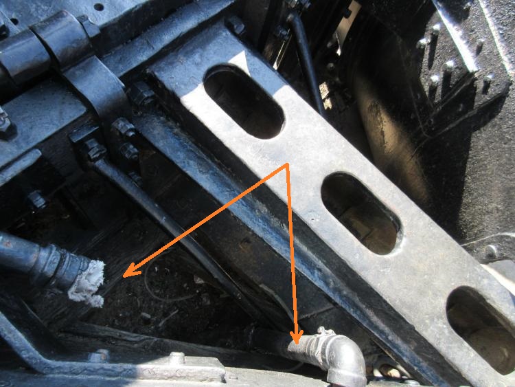
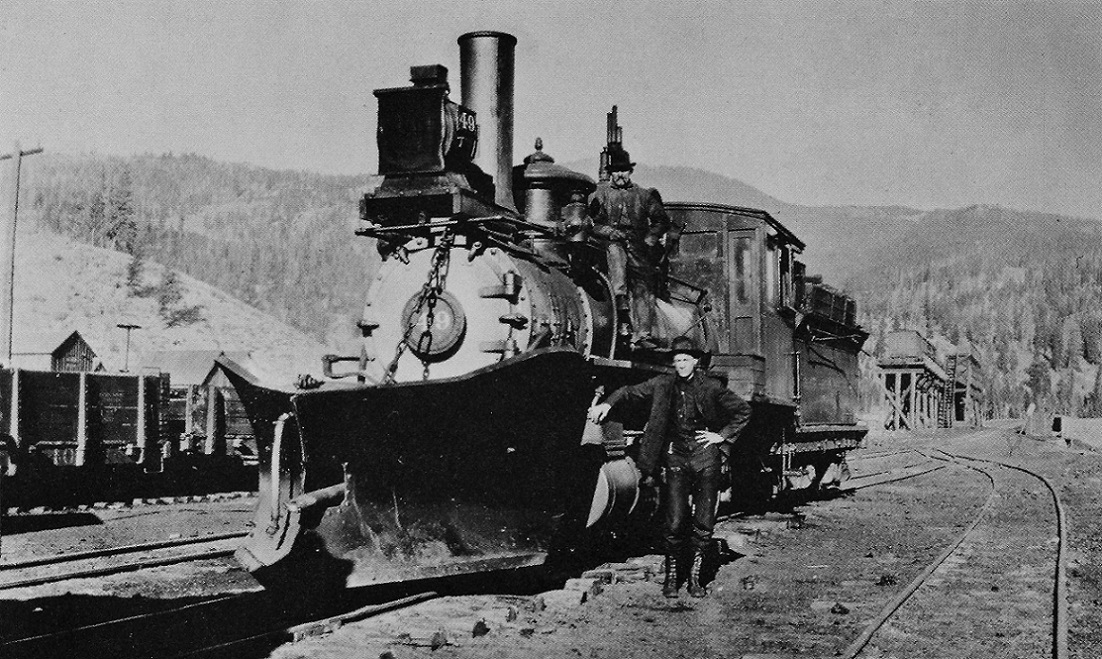
Re: Hinged Pilot Plows
|
|
Re: Hinged Pilot Plows
|
|
Re: Hinged Pilot Plows
|
|
Re: Hinged Pilot Plows
|
|

Re: Hinged Pilot Plows
|
|
Re: Hinged Pilot Plows
|
|
Re: Hinged Pilot Plows
|
Administrator
|
Re: Hinged Pilot Plows
|
|
Re: Hinged Pilot Plows
|
Administrator
|
| Free forum by Nabble | Edit this page |