a new (old) #59?

1234567
1234567

|
This post was updated on .
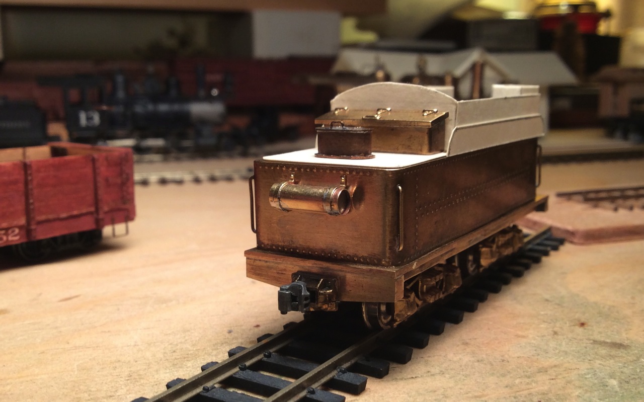
I decided to go ahead and shorten the frame of my tender, following as closely as I could the dimensions of #59's tender in 1923, as I described in my last post. Here's the PFM tender taken apart:
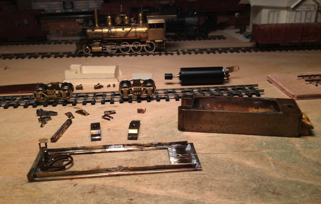 The cistern of the model is about 3" too long. I think I'll place the trucks at the correct distances from the ends, so that makes them about 3" too far apart. Here's a test assembly with the shortened frame, with the parts just stacked up on each other to see how it looks. 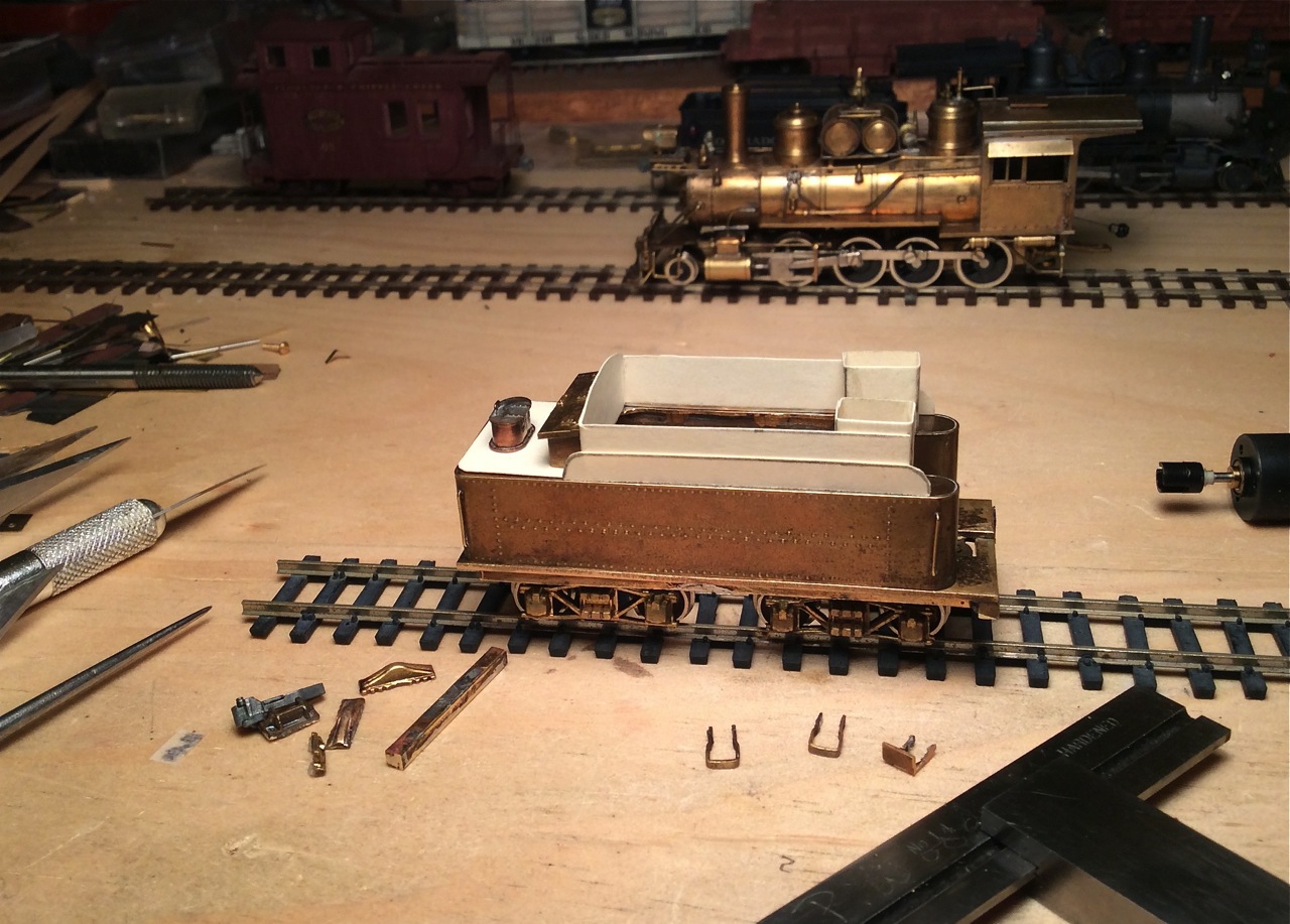 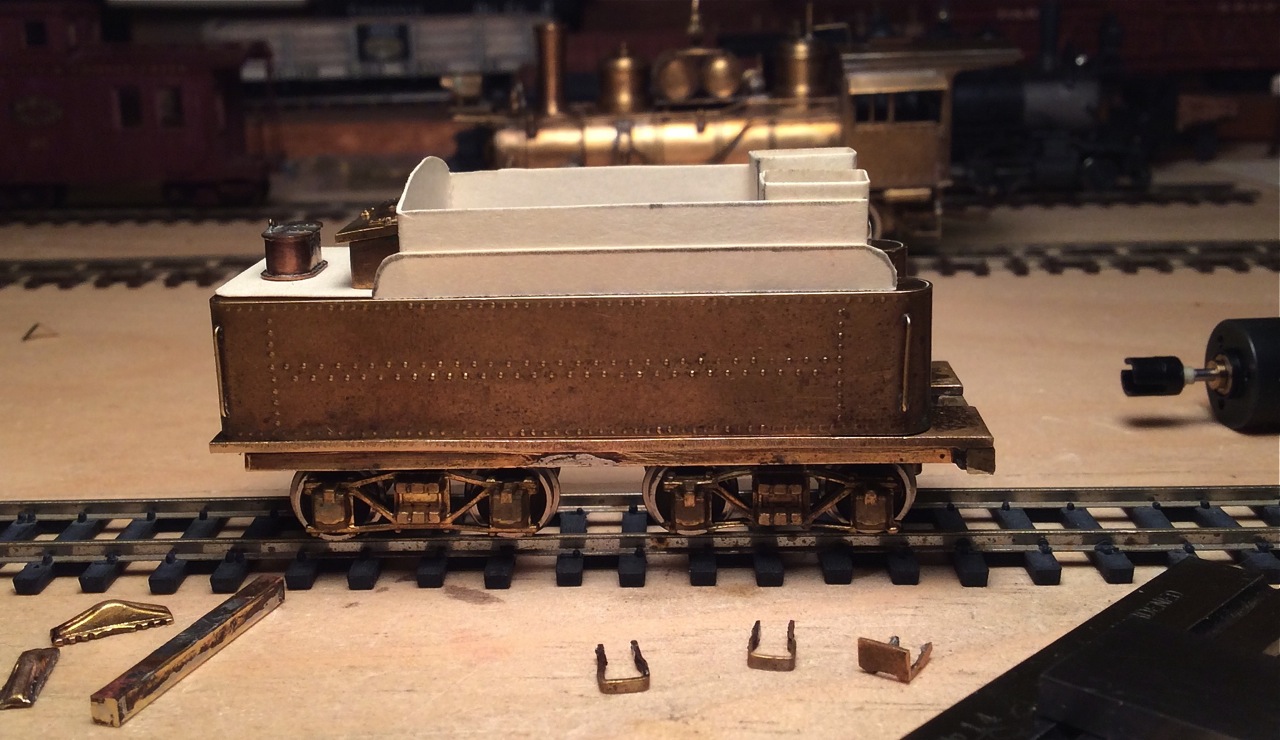 I will remake the rear crossbeam (what's the right name for it?). Instead of using the straight one originally on the model that's sitting there in the foreground of the photo, it'll be deeper in the middle at the draft gear and tapering in depth out to the ends, as I see on various C&S tender photos. I borrowed a water hatch of roughly the right size, that I made 40 years ago for another tender, to see how the rear deck arrangement works out. The toolbox from the PFM model looks about right there-- I think? I'd be grateful for any comments/corrections at this stage. I think I might make the coal bunker 6" shorter, to leave the rear deck 5'6" instead of 5' as it is here. That would better match the tender on 59 in the Central City photo, I believe. So, all comments/thoughts/corrections eagerly solicited at this stage before I solder the frame back together and fabricate the top pieces. thanks! John
John Greenly
Lansing, NY |
|
|
Looks good to my envious eyes! Bill Uffelman On Thursday, August 10, 2017, 11:56:19 PM EDT, John Greenly [via C&Sng Discussion Forum] <[hidden email]> wrote:
I decided to go ahead and shorten the frame of my tender, following as closely as I could the dimensions of #59's tender in 1923, as I described in my last post. Here's the PFM tender taken apart:
 The cistern of the model is about 3" too long. I think I'll place the trucks at the correct distances from the ends, so they are about 3" too far apart. Here's a test assembly, with the parts just stacked up on each other to see how it looks.   I will remake the rear crossbeam (what's the right name for it?). Instead of using the straight one originally on the model, it'll be deeper in the middle at the draft gear and tapering in depth out to the ends, as I see on various C&S tender photos. I borrowed a water hatch of roughly the right size, that I made 40 years ago for another tender, to see how the rear deck arrangement works out. The toolbox from the PFM model looks about right there-- I think? I'd be grateful for any comments/corrections at this stage. I think I might make the coal bunker 6" shorter, to leave the rear deck 5'6" instead of 5" as it is here. That would better match the tender on 59 in the Central City photo, I believe. So, all comments/thoughts/corrections eagerly solicited at this stage before I solder the frame back together and fabricate the top pieces. thanks! John If you reply to this email, your message will be added to the discussion below:
http://c-sng-discussion-forum.41377.n7.nabble.com/a-new-old-59-tp8562p9052.html
To start a new topic under C&Sng Discussion Forum, email [hidden email] To unsubscribe from C&Sng Discussion Forum, click here. NAML |
|
|
This post was updated on .
In reply to this post by John Greenly
Next installment-- I hope you all are not all bored with these reports, this helps motivate me to get something done!
I went ahead and made the new tender end beam (sill?), and installed it and the bolsters in the frame. I mounted the coupler pocket, which is the original PFM one, slightly modified to take the Sergent Engineering coupler. This is a coupler height check, it came out an inch or so too low- easy to fix. I got dimensions for this beam from a nice photo of the back end of No. 68's tender in NG Pct. VI p. 166. I also shortened the mockup coal bunker by 6", so the back deck is now 5'6" long, and I think it does come closer to 59's tender. My working concept here is that the tender first was modified to the intermediate form that I'm modeling, though there's no evidence that I know of. Then, by 1923 it definitely had been changed to the final version in the Central City photo, but I'm supposing that the bunker stayed the same length. Seem reasonable?? Here's a view from a perspective roughly like the Central City 1923 photo: 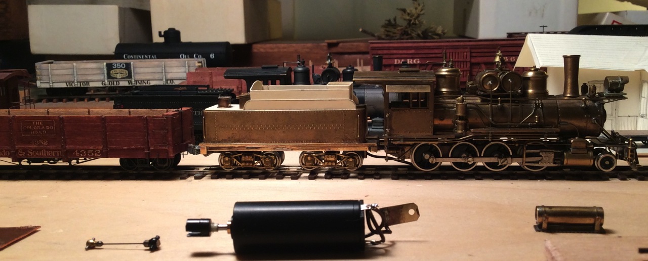 And here are a couple of closer looks at the changes. 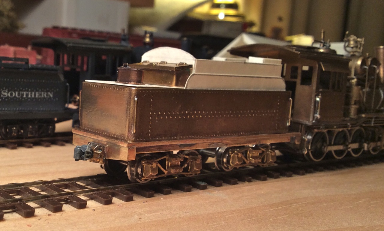 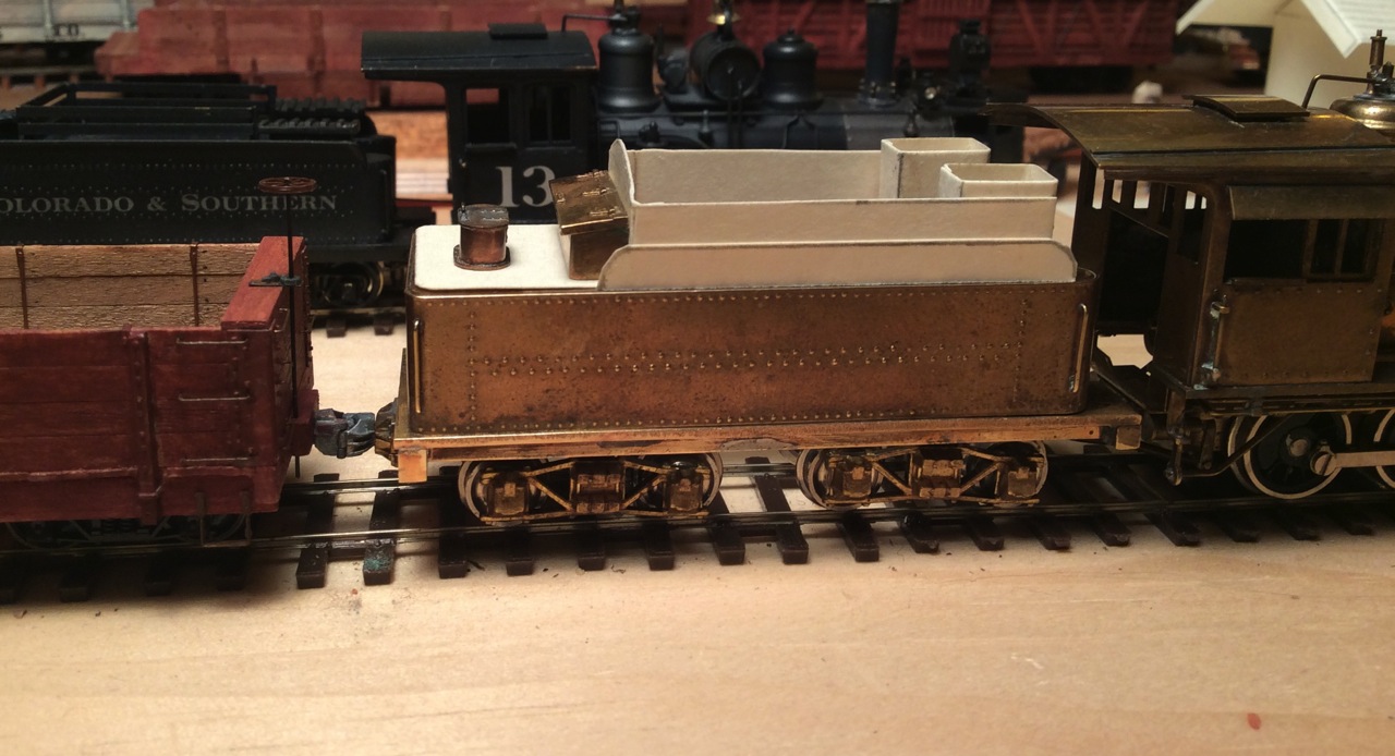 Again, please tell me if something doesn't look right, or isn't consistent with what you know. I can always change things- the great thing about soldering is that it's reversible!! thanks, John
John Greenly
Lansing, NY |
|
|
Looks great. Thanks for sharing your work. Bill Uffelman On Friday, August 11, 2017, 11:40:12 PM EDT, John Greenly [via C&Sng Discussion Forum] <[hidden email]> wrote:
Next installment-- I hope you all are not all bored with these reports, this helps motivate me to get something done!
I went ahead and made the new tender end beam (sill?), and installed it and the bolsters in the frame. I mounted the coupler pocket, which is the original PFM one, slightly modified to take the Sergent Engineering coupler. This is a coupler height check, it came out okay. I got dimensions for this beam from a nice photo of the back end of No. 68's tender in NG Pct. VI p. 166. I also shortened the mockup coal bunker by 6", so the back deck is now 5'6" long, and I think it does come closer to 59's tender. My working concept here is that the tender first was modified to the intermediate form that I'm modeling, though there's no evidence that I know of. Then, by 1923 it definitely had been changed to the final version in the Central City photo, but I'm supposing that the bunker stayed the same length. Seem reasonable?? Here's a view from a perspective roughly like the Central City 1923 photo:  And here are a couple of closer looks at the changes.   Again, please tell me if something doesn't look right, or isn't consistent with what you know. I can always change things- the great thing about soldering is that it's reversible!! thanks, John If you reply to this email, your message will be added to the discussion below:
http://c-sng-discussion-forum.41377.n7.nabble.com/a-new-old-59-tp8562p9059.html
To start a new topic under C&Sng Discussion Forum, email [hidden email] To unsubscribe from C&Sng Discussion Forum, click here. NAML |
|
Administrator
|
In reply to this post by John Greenly
Hi John, you are off to a great start, nice job!
Keith pointed out a while back, correctly, I might add, that most of my area if interest falls in the last 10 to seven years preceding abandonment of mainline operations. Anyway, here goes... Don't worry at all about the tank resting so close to the end of the frame.you'll be fine with what you have, as long as you can get the cut lever brackets between the back of the cistern and the edge of the end beam. I'm not 100% on dimensions of the rear tank in those (your) days, but in later days, your air tank would be 12" in diameter, 33" or 36" long, and would have a triple valve on it with a small pipe with a controller at the front of the bunker side on the engineers side. In your days, there may not have been a retainer used, so that valve and pipe may not have been present. The air tank may also have been centered, not shifted to the right as it was in later times. There were almost certainly three grabirons at the rear deck (water hatch) around the end and sides, for safety. There were probably marker light brackets at the corners. #7, in 1899 still carried DSP&P style cage lamp holders in the corners so that has been around forever. I'm sure there were grabirons on both sides of the end beam as well. Not sure about rerail frogs... Also, don't forget the water valves at the front of the water legs, at the front of the tool boxes that wouldn't have those wind screens yet. Mike |
|
|
In reply to this post by John Greenly
Looking good! Keep going and keep sharing.
Keith Hayes
Leadville in Sn3 |
|
|
In reply to this post by Mike Trent
Mike Trent writes:
>Anyway, here goes... Don't worry at all about the tank resting so close to the end of the frame.you'll be fine with what you have, as long as you can get the cut lever brackets between the back of the cistern and the edge of the end beam. I'm not 100% on dimensions of the rear tank in those (your) days, but in later days, your air tank would be 12" in diameter, 33" or 36" long, and would have a triple valve on it with a small pipe with a controller at the front of the bunker side on the engineers side. In your days, there may not have been a retainer used, so that valve and pipe may not have been present. The air tank may also have been centered, not shifted to the right as it was in later times. >There were almost certainly three grabirons at the rear deck (water hatch) around the end and sides, for safety. There were probably marker light brackets at the corners. #7, in 1899 still carried DSP&P style cage lamp holders in the corners so that has been around forever. I'm sure there were grabirons on both sides of the end beam as well. Not sure about rerail frogs... >Also, don't forget the water valves at the front of the water legs, at the front of the tool boxes that wouldn't have those wind screens yet. >Mike Hi Mike, many thanks for this information!! As you noticed in the last photo I posted, there is only 4" of frame deck projecting beyond the back end of the cistern. I think photos show that some frames were about like that, though some were definitely a few inches longer, but I think this does give me enough room for the cut lever brackets. By the way, I'm still wondering-- do you know why the original, long rear frame decks disappeared on the later tenders? Could it have had anything to do with safety? I'm thinking about this comparison: 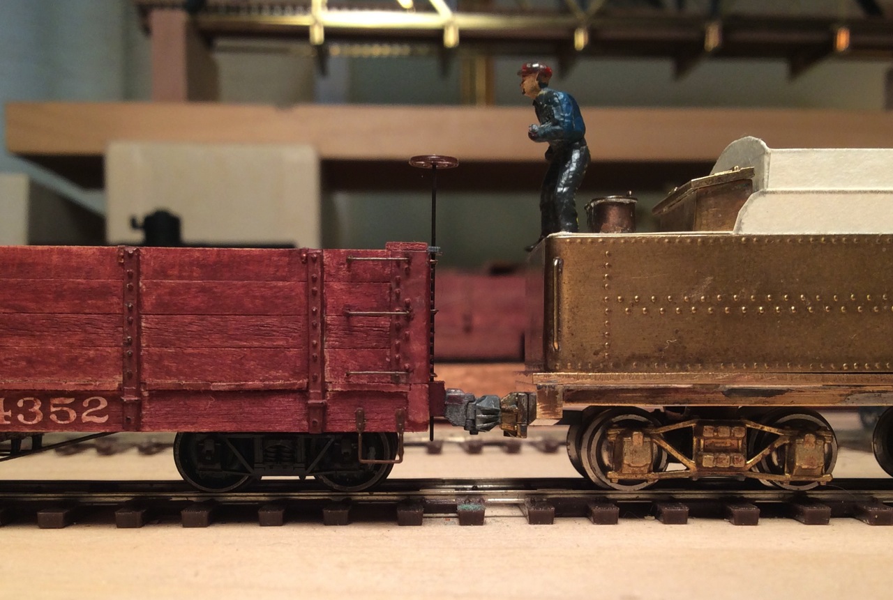 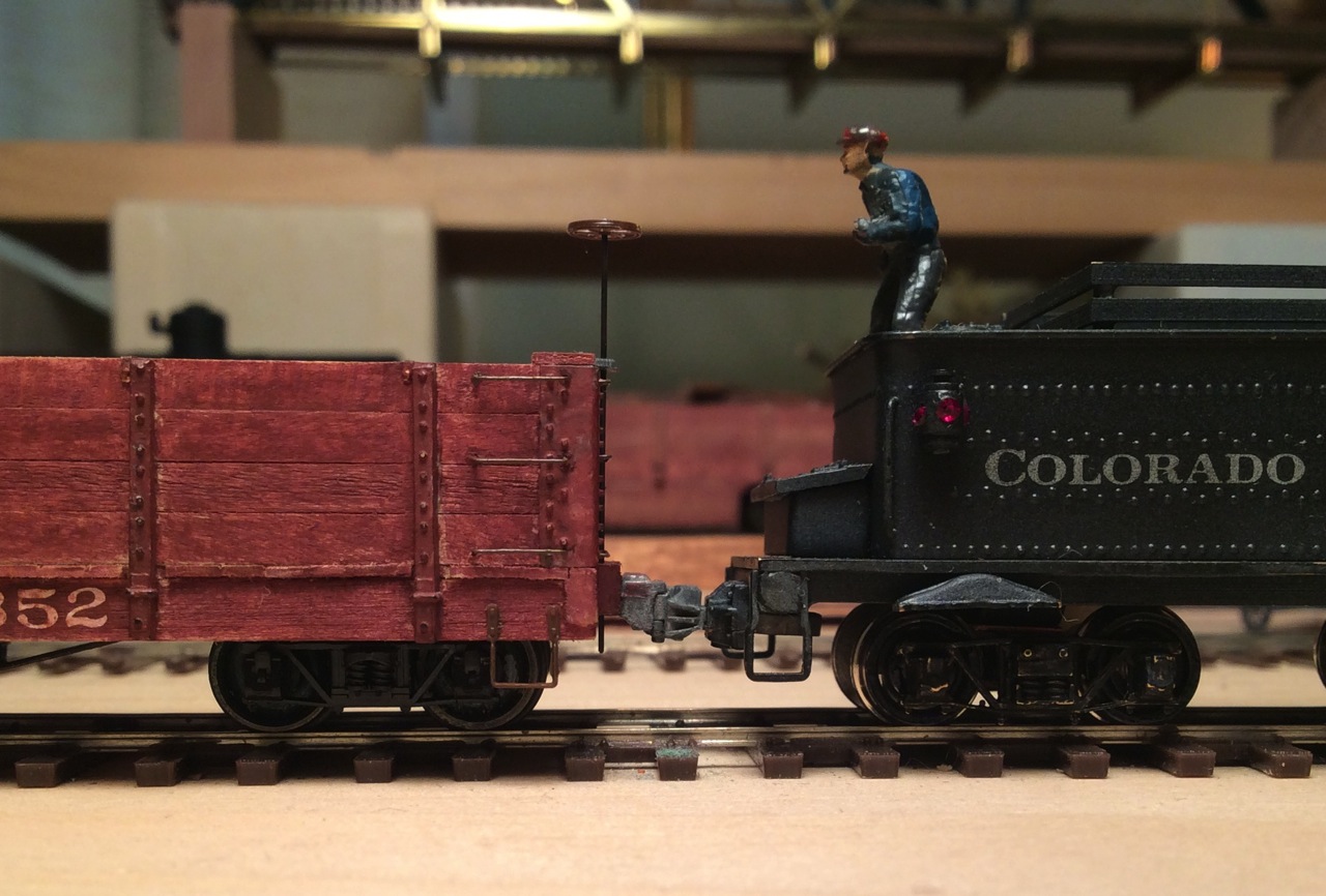 Maybe some of you with real railroad experience could say if one of these is easier to climb across than the other (if the grabirons, stirrup steps, and the air tank were in place on the new one)? Or was there some entirely different reason for eliminating the back frame deck? Anyway, Mike, the grabiron positions you describe will be the ones I'll do. Every photo I've found of the intermediate and modern tenders shows the three long grabirons around the edges of the back deck, and likewise all that are visible do have a grabiron on each side of the end beam, just as you say. I don't have a good photo of the back end of a tender from my 1918-ish time frame, so I'm relying on later photos. I hadn't noticed that the air tanks were to right of center- I'll have to look for that. I think I saw a photo from around my time with a retainer valve on the engineer's side, and I will put one on the model. As to the air tank, I'll use your dimensions. Definitely will have the marker lamp brackets at the back corners, yes, a real C&S thing. Rerail frogs weren't always there, but I see the (empty) brackets for them in some photos, so I'll put them on. I've bought some very nice water valve castings from Wiseman, they'll look good! again many thanks for your help and encouragement! and thanks, Keith! John
John Greenly
Lansing, NY |
|
|
John, it seems that the ease of access and logical placement of Grabirons and Steps for safe passage about the locos when performing ones duties never entered the heads of early designer's and official's heads .... and that idealogy persisted .... and noting the new locos recently put into service here...still persists. Only repeated injuries to crew would result in any change though there. I'm thinking that if they saved $100 on materials then that would be the reason.
UpSideDownC
in New Zealand |
|
Administrator
|
This post was updated on .
Chris is spot on. Anything to save a buck. John, could be the B4F class was the only one with offset air tanks. The others are centered, but the height varies.
The answer to the reason for the rear platform probably goes back to the old days when they carried a large air tank there. That big tank was replaced by the boiler top mounted tanks in the early 1900's. The small tank used later on the rear of the cistern was the reservoir for the tender brakes, usually found underneath as on D&RGW equipment. As the tender frames were rebuilt, most of the rear floor decks disappeared. #60 is a very notable exception. Following is a photo of "Old No. 7" which shows the old train air tank on the rear platform, with the smaller tender reservoir above it. I put the triple valve on it because I think there was one on there in the 1890's in DL&G days. 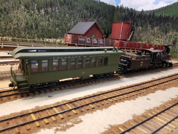
|
|
|
This post was updated on .
The answer to the reason for the rear platform probably goes back to the old days when they carried a large air tank there. That big tank was replaced by the boiler top mounted tanks in the early 1900's. The small tank used later on the rear of the cistern was the reservoir for the tender brakes, usually found underneath as on D&RGW equipment.
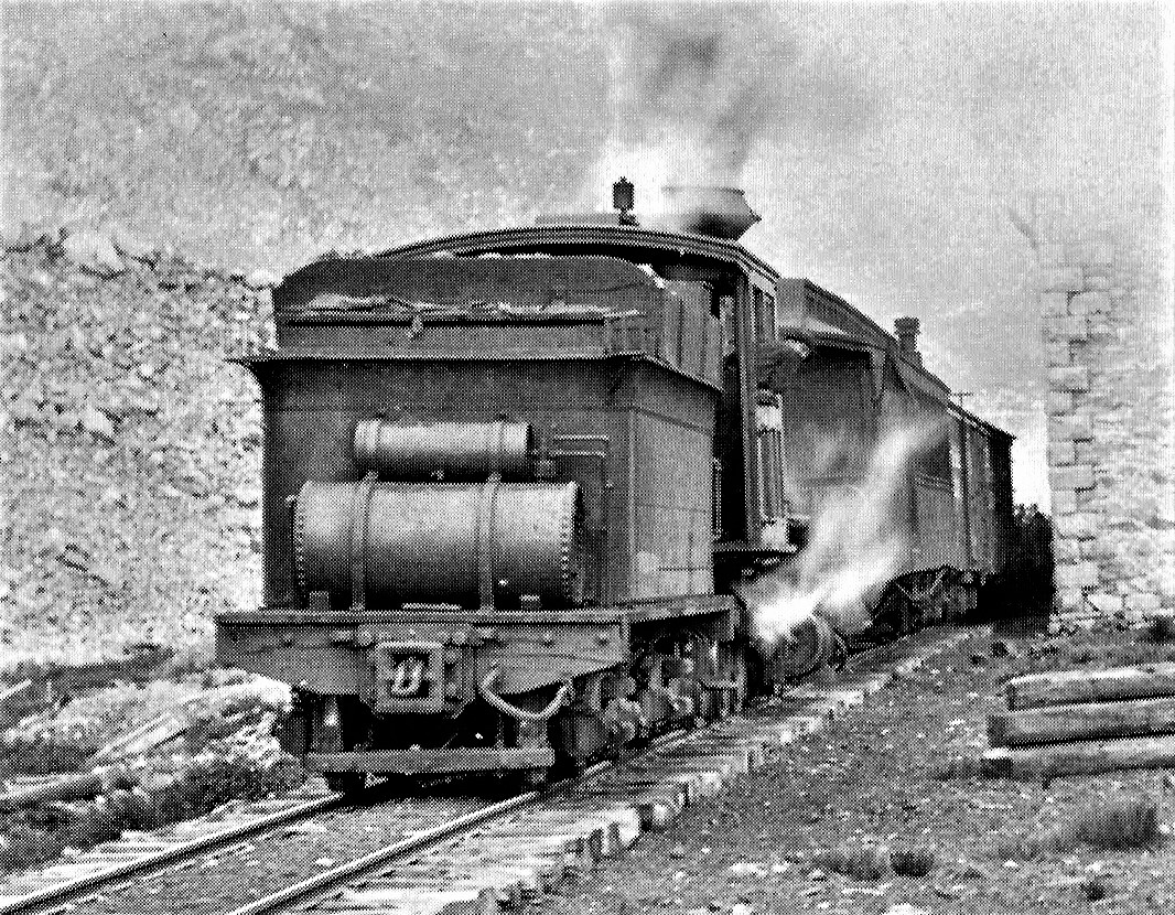 In Kindig, et al, The Pictorial Supplement . . . My colleague, Dr. Scott, provided us a pretty clear photo of the rear of a Cooke 2-8-0 tender to illustrate these details. The locomotive is the rear helper on a DL&G mixed train at the Alpine engine house in the late 1890s. The small air reservoir with triple valve, for the tender brakes, is already in place, but Mike's right, I don't see the retainer piping to the engineer's side of the tender, just below the collar, that was present by the early 1900s. Perhaps tender retainer valves were introduced by the new C&S. 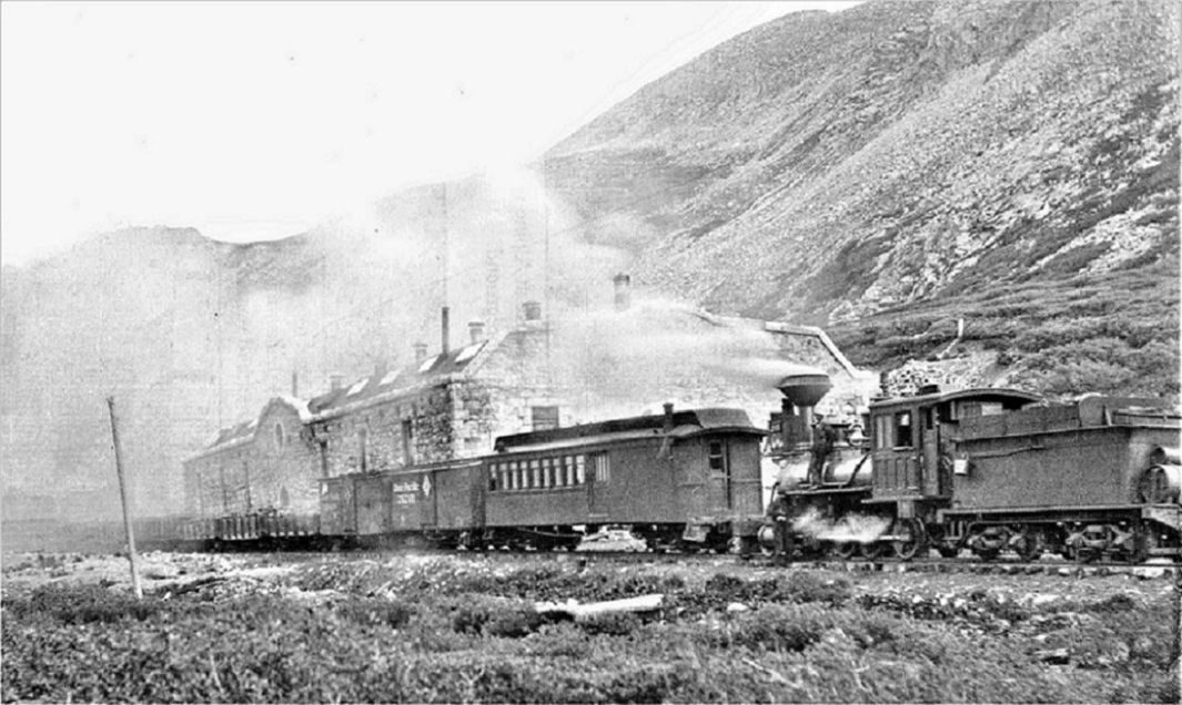 In Kindig, et al, The Pictorial Supplement . . . But this photo of C&S number 7, the prototype of Mike's model, taken about 1900-1901, does seem to have a retainer on the tender collar just behind the cab . . . or I think I can see it! At least at the tender rear, just under the collar, there seems to be the retainer pipe, bending around to connect to the triple valve. 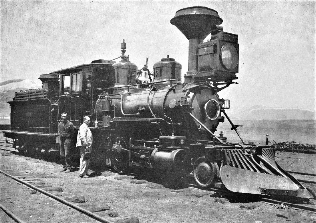
Jim Courtney
Poulsbo, WA |
|
|
In reply to this post by Chris Walker
All this interesting talk about air tanks side-tracked me from starting on replacing the paper coal bin. Instead I made up a tank for my tender tonight, so here it is, pasted on roughly with glue to see how it looks:
 Chris, I'm sure you're right about neglect of safety considerations. Now that I see this on the tender, it's clear that the air tank is there to step on. I can't imagine NOT using it that way to hop over to the car behind: 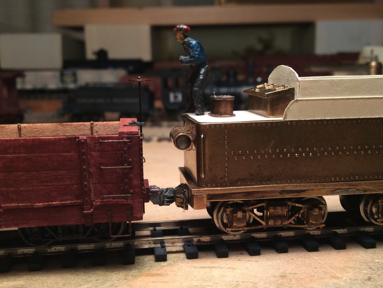 Safe... I don't know. Convenient, for sure! Thanks, Mike and Jim for the additional photos. However this tender turns out, I'm learning loads of new stuff and having a lot of fun doing it! John
John Greenly
Lansing, NY |
|
|
This post was updated on .
Well, little models are pretty uninteresting compared with 1:1 scale live steam at Como, but I made a little progress with my tender tonight, a new top plate for the cistern. Here are a couple of photos.
Here's what remained of the original PFM tender cistern: 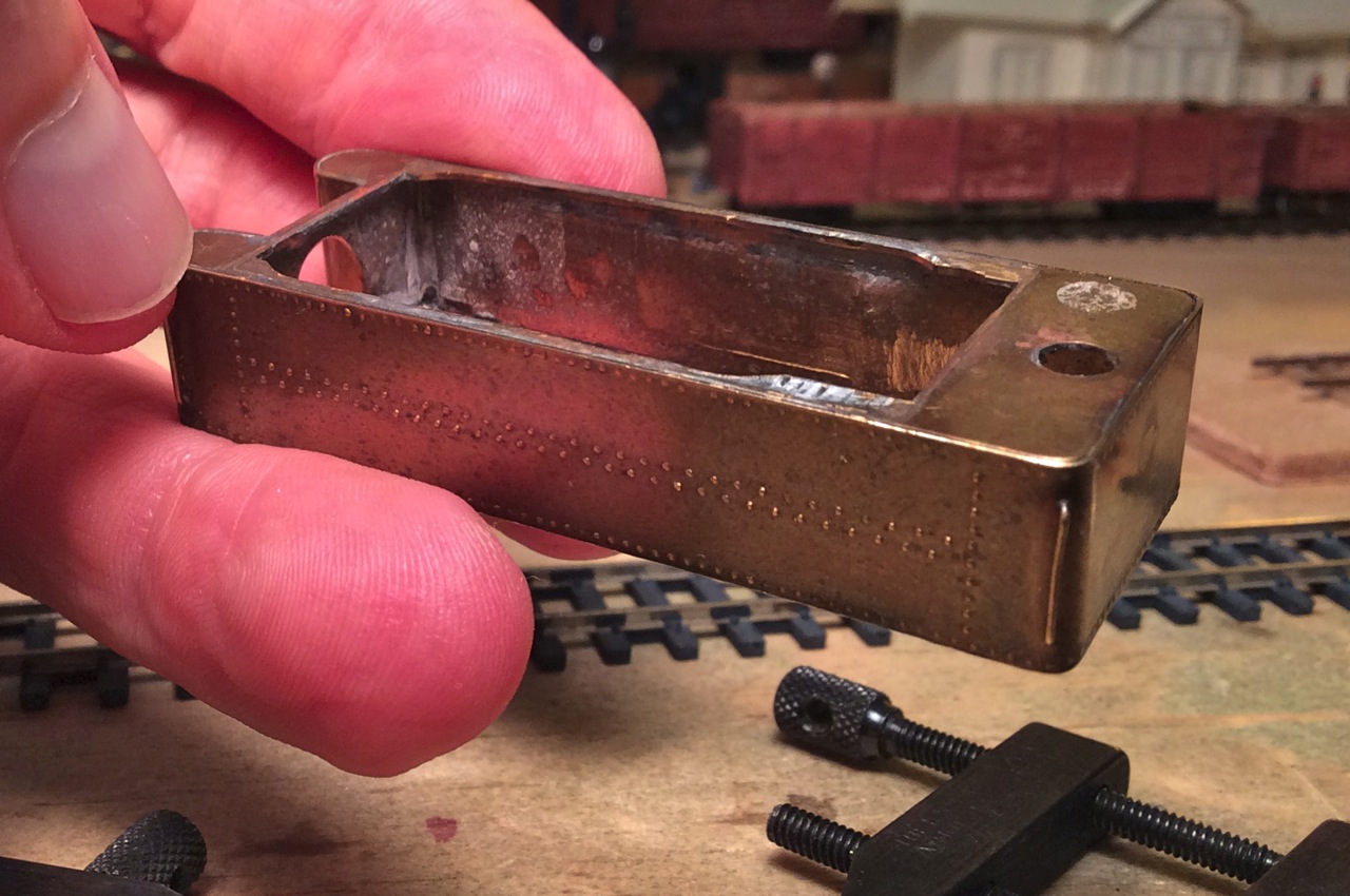 After taking off the old parts, here it is with the new top set in place for a test fit: 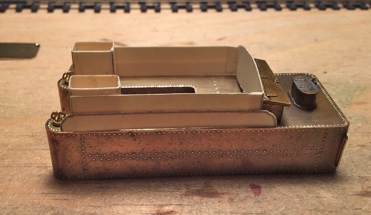 Being a lazy riveter, I only used rivets in where they would be visible: 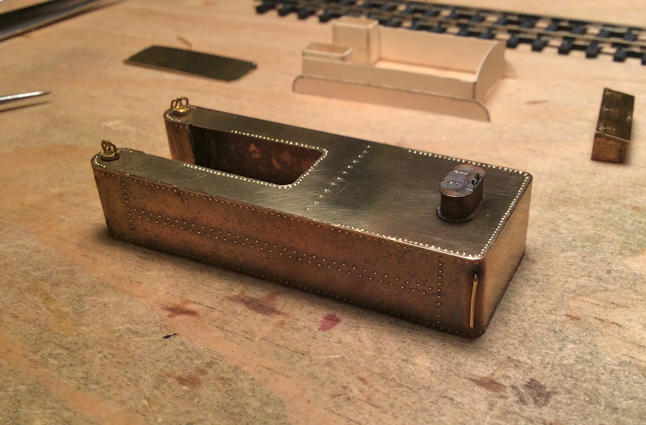
Since I had to take the front end all apart anyway, I took the opportunity to re-bend the front ends of the cistern legs to shorten the total length by about 3", so now it's just about 17' 6" long. So here's a test fit, the relation to the back end beam looks better I think: 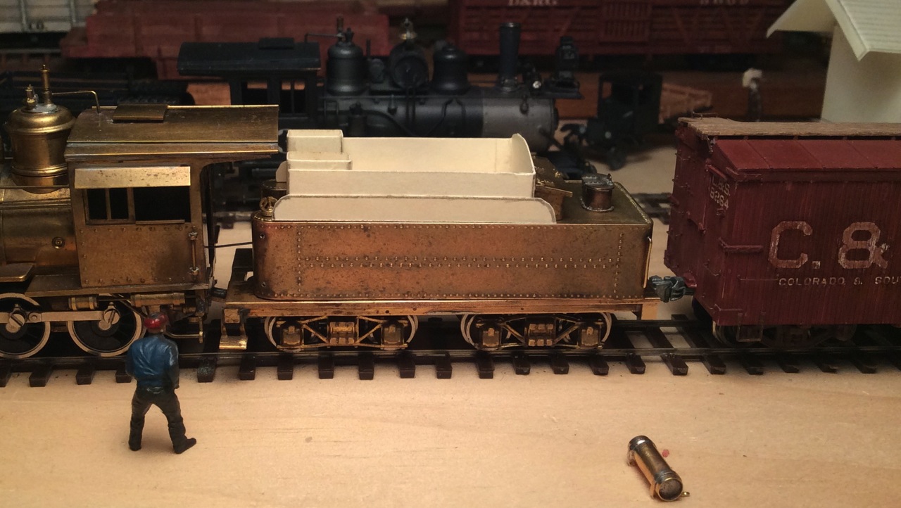 So, now I'm ready to fabricate the remaining superstructure. This really is fun-- but I would rather have been in Como today! Cheers, John
John Greenly
Lansing, NY |
|
|
Project is really coming along. Thanks for sharing.
Bill Uffelman
|


|
|
In reply to this post by John Greenly
Well, haven't had much modeling time lately what with needing to make six 1:1 scale barn doors before winter comes on, and endless other things. But, last night I finally got around to soldering up the new superstructure for my attempt at an intermediate tender. Here are the new parts that have been patiently waiting the last two months, along with the original PFM cistern shell and toolbox:
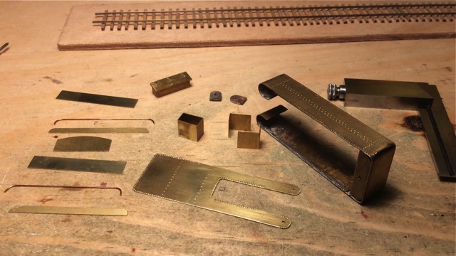 and (editing out the swearing and burned fingers part) here it is all put together: 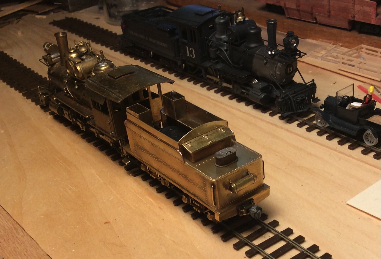 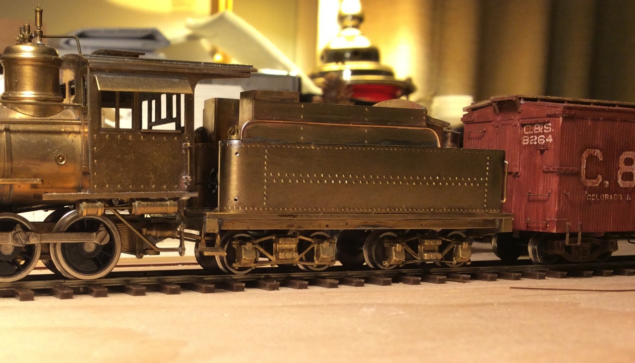 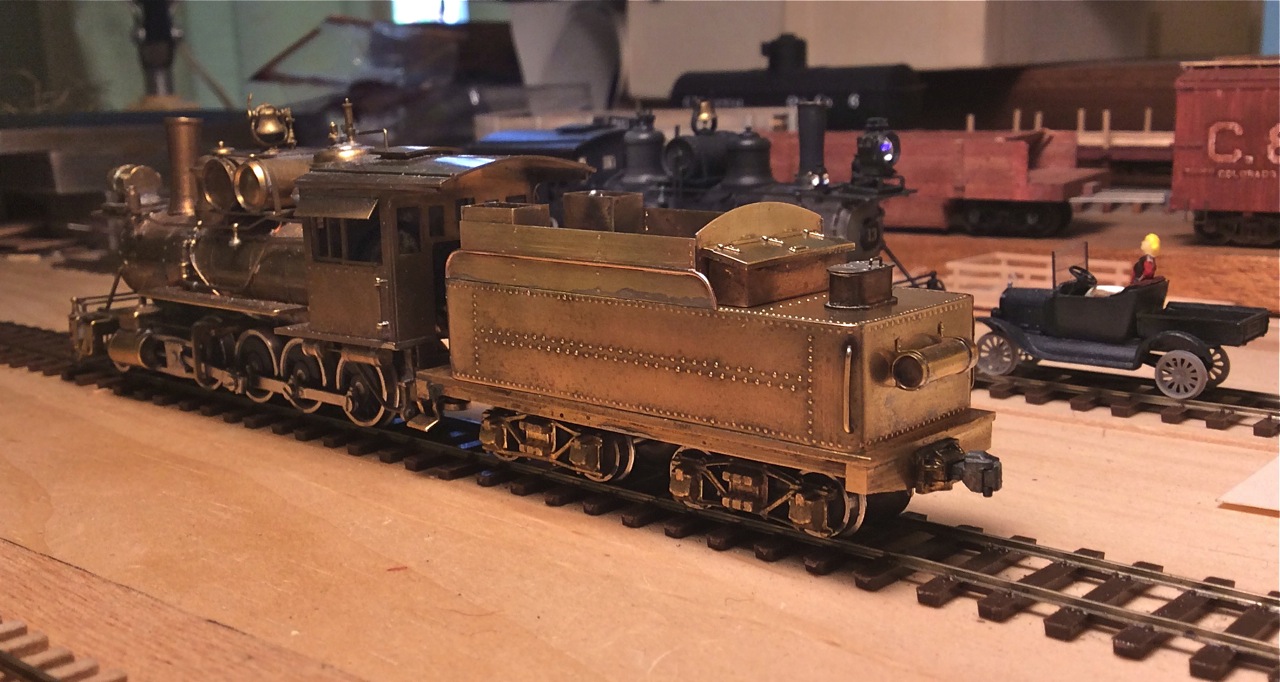 Well, I hope it's starting to look recognizably C&S-intermediate-tender-ish? There shouldn't be a visible joint between the top edge of the tank side and the straightened-up side pieces (the remaining parts of the original flare). I didn't dare try to entirely fill that joint for fear of solder flowing out over and obscuring the rivets on the tank. Before I paint the tender I'll fill that joint in with some epoxy fairing compound to make it invisible. Eventually I'll get around to moving the motor into the loco, just need to make a gearbox- I hope NWSL makes a suitable idler gear for these old PFM models. It runs so smoothly now with the Faulhaber motor in the tender and the reworked universal drive that I'm not in a hurry to do that job, but after I do that it'll clear the space for the coal boards, the backhead and firebox door, and all the other details in the fireman's domain in both tender and engine. But right now as I look at these photos I just want to put on the right handrails everywhere. Those remaining original grabirons look really gross now! Mike, Jim, Keith, thanks so much for all the help you've given me with this project already! John
John Greenly
Lansing, NY |
|
|
Looks great John. Not sure what I did, but my hat is off to you--I will work in everything short of brass. Wow.
Keith Hayes
Leadville in Sn3 |
|
|
Keith,
Working in brass is not that bad or hard. It is like most things, understand the principals of working with it and have some decent tools for working with it. It is a fairly forgiving material in many ways in my experience. I did a lot of re detailing and modifying of brass models back in the late 1970s and early 1980s. I did a lot of the work with a MicroFlame torch which took some practice to use and not take a model totally apart…LOL. Later on I got a resistance soldering unit. I still have all the tools and even some better ones today but just don’t find myself needing to do as much modifying of models. That might change if I get deeper into modeling the C&S. Best, Todd Ferguson
|
|
Administrator
|
Beautiful work, John. I share Keith's consternation with brass. While I greatly admire those who have the patience and skill to work seriously in that medium, I don't share it to the extent necessary to do what I would need to do.
But if I have demonstrated anything through the work I've done in the last 37 years, it might be that compromising the medium of brasswork can and does hold up well over time. Just don't ever strip the paint off! |
|
|
Thanks, Mike,
but your beautiful engines are an inspiration to anybody working in brass- like me! I did a lot of soldering when I was a kid, I think I was better at it then. Probably poisoned myself with lead fumes…. So I'm glad that you have already got me thinking of other adhesives than solder for some of the fiddly bits. If it's worked for you for 37 years, that's good enough for me. Speaking of fiddly bits, I made up a set of the tender top rails just now. Here they are: 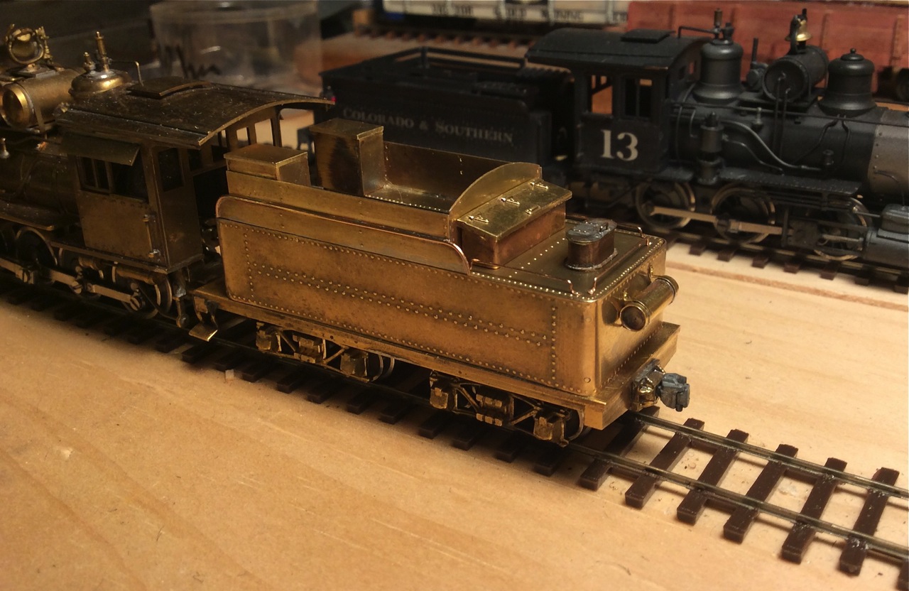 The best photos I could find to see how they were made were of #60's tender (posted in the #60 tender thread). Those had flattened ends riveted to the tank, so I made mine that way. The smallest wire I could do that with is .0125, or a little over a scale inch. Probably somewhat too big, but I think it looks all right. I used the photos of the intermediate tenders on #58, 65 and 70 (posted earlier in this thread) to measure the height of the rails above the tank deck. They stand a good bit further off the surface than typical grabirons, but I think this is pretty much right, at least I hope so. Next I need to figure out how to make those neat marker lamp brackets to put at the back corners. John
John Greenly
Lansing, NY |
|
Administrator
|
Hi John, thanks.
Check PSC for the early style baskets. If they were produced by Kemtron ages ago, PSC may have them. I have used PSC #60 marker brackets, and also ones that were made for #69 and #58 For more modern ones. I was also fortunate to have been able to find a few Overland parts, those appeared on eBay after the builder unloaded spare parts. That stuff was sold by both Keith Wiseman, and by "brassmonger" Bill Davis in O Scale. Not sure about S and HI. But do check PSC. I think their catalogs are available on line. |
|
|
This post was updated on .
Hi all,
an update on my old PFM rebuild into a Rhode Island engine, probably 59. I still have detail work to do on the intermediate tender, but the many incorrect things on the engine were bugging me, so I've started to work on it. I've put a lot of detail in this post, probably not of interest to most, but I thought that there must be a lot of these old models around and if somebody else wants to do a rebuild, some of the information here and in this thread earlier might be useful. Here's how my engine is today: 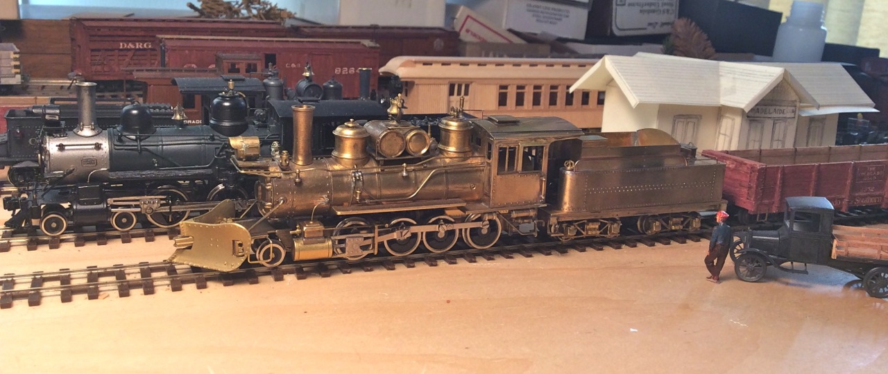 The most obvious thing is that I have just yesterday come into possession (thank you!!!!!!) of a PSC pilot plow, and here it is being tried out. It needs some further fitting and adjustment, but I really like it a lot, it just says C&S to me. I've started to search for information on how the chains that hold the plow were attached. I've looked at many photos of plows, but so far I haven't found one that shows the inside of the plow and these attachments. I'd greatly appreciate help with this. 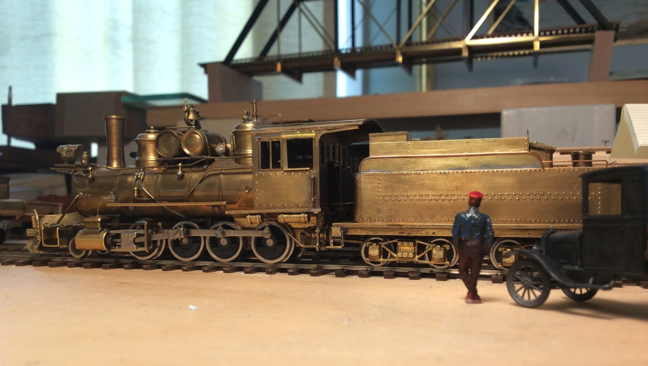 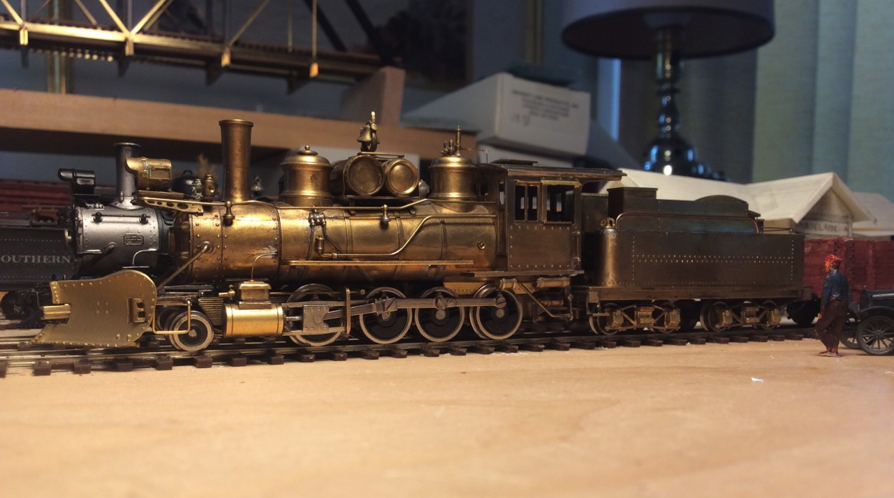 I've also done several other things that aren't so obvious. Starting at the cab end, I removed the original huge awning over the windows, which was a pain because it was integral to the cab structure, not a separately stuck-on part. Serious Dremel cutoff-wheel surgery. After dealing with this the fun part was removing the second window, putting in a central vertical frame piece and adding a small shade over the open window, all approximately like the photo of 59 at Central City. I put in a firebox (may remake that, I think it doesn't extend quite far enough forward, should extend to the third axle location?). I extended the boiler into the cab. Haven't started interior or backhead detail yet, but it already looks better without that big empty cab. The tender drive wire can go through a small hole in the firebox door- or maybe I'll make the door opened. The engine is running so nicely now that I think I'll leave the tender drive as is, at least for the present. There is one advantage to tender drive on an HOn3 engine, that is, there's room for a lot more weight in the boiler for traction and smooth running. After careful adjustment of the mechanism and with the excellent Faulhaber motor in the tender, it's so smooth that there is no vibration of the tender and it can start up imperceptibly- it's the best running engine I've ever had. Moving toward the front end, I've fixed some wrong dimensions. PFM mounted the cylinders almost 6" too far forward (from folio dimension) so that the saddle was bearing on the rivet line of the smokebox extension, and was not in line with the stack either. I moved the cylinders back to the correct position, which required cutting back the notch in the frame that carries the saddle and boring out the hole in the saddle that the boiler mounting screw passes through. This required eliminating the separate concentric screw that fixed the saddle to the frame, so now the saddle is simply clamped between frame and smokebox by the single screw. The pilot wheels were 9" too far forward as well, so I moved that back too. Here's how the front end is now: 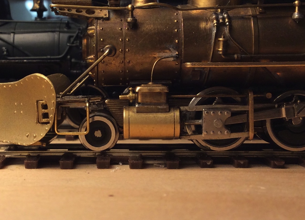 The original crosshead guides are exactly correct to accommodate the piston travel, in this position. It's a close fit, but works perfectly. Now I need help. I've been trying to find a correct headlight and stack. Here's a headlight in the PSC catalogue, I don't know if it is really right, there are no dimensions given, only this drawing: 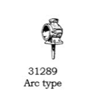 I've not been able to find anything that looks right for the shotgun stack. It's the unique C&S flared base connection that I haven't found. It looks to me that these same stacks (generally cut down in height) were used with the Ridgeway addition. The original PFM Ridgeway stack itself was very crude, though the spark arrestor casting is very nice. I also have a PSC Ridgeway stack, but it does not reproduce the flared base connection at all. Here's a different stack base in the PSC catalogue. If it's the right diameter, I could make the stack, with a curved flare at the bottom, to put on it:  But, again, I have no dimensions for this. The stacks listed to go with it are a diamond stack and two straight capped stacks. So, I don't know whether either the headlight or stack base will be right. I've not found anything in Wiseman's catalogue or anywhere else. I'd be very grateful for any help and information about either of these. thanks, John
John Greenly
Lansing, NY |
«
Return to C&Sng Discussion Forum
|
1 view|%1 views
| Free forum by Nabble | Edit this page |