The C&S Coal Chutes: Pine, Como, Dickey, Pitkin and almost Breckenridge
1 ...
456789


1 ...
456789
|
I'm modeling the area around Selkirk, and was very surprised to find that there was a coal house and chutes there, as well. Looking at the ICC Valuation maps, it's obvious they are very different than the ones we have been discussing, but would love to see if anyone has any additional info to share. Here the maps showing the details:
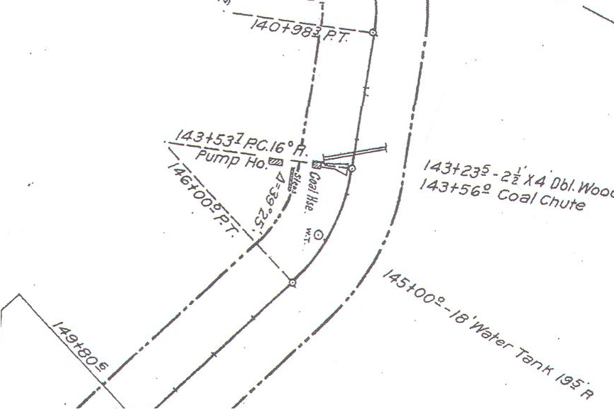 I also have a great photo of the Selkirk Tank, if anyone needs it. All the best, Don |
|
I also have a great photo of the Selkirk Tank, if anyone needs it.
Yes, please share the tank photo with us! And a great find, a previously unknown coal bin and chute! Was this the 1918 Valuation map? Perhaps John could check his records of the "DL&G and C&S internal records and includes data the railroad submitted to the State Board of Equalization, if reported, in 1890, 1898 and 1909" and see if there is a mention that shows up there. I've checked Cliff Mestel's DSP&P/DL&G B&B listings for years up to 1894, and the only thing mentioned at Selkirk was a spur. Jim
Jim Courtney
Poulsbo, WA |
|
This post was updated on .
Well Jim,
I guess we know there was a whole lot more there than that =D Yes, map is from a 1918 Valuation Summary Map given to me by Bob Schoppe. Here is the tank photo, also given to me by Bob. Note how small the tank side boards are - almost looks like scrap wood. It also appears to be completely void of paint. Its appearance is almost identical to the tank at Baker, with the exception of the additional reinforcing cables at the tank base, and the slightly different fasteners on the tank bands. Based on the Ridgeway Stack it's probably post 1918. 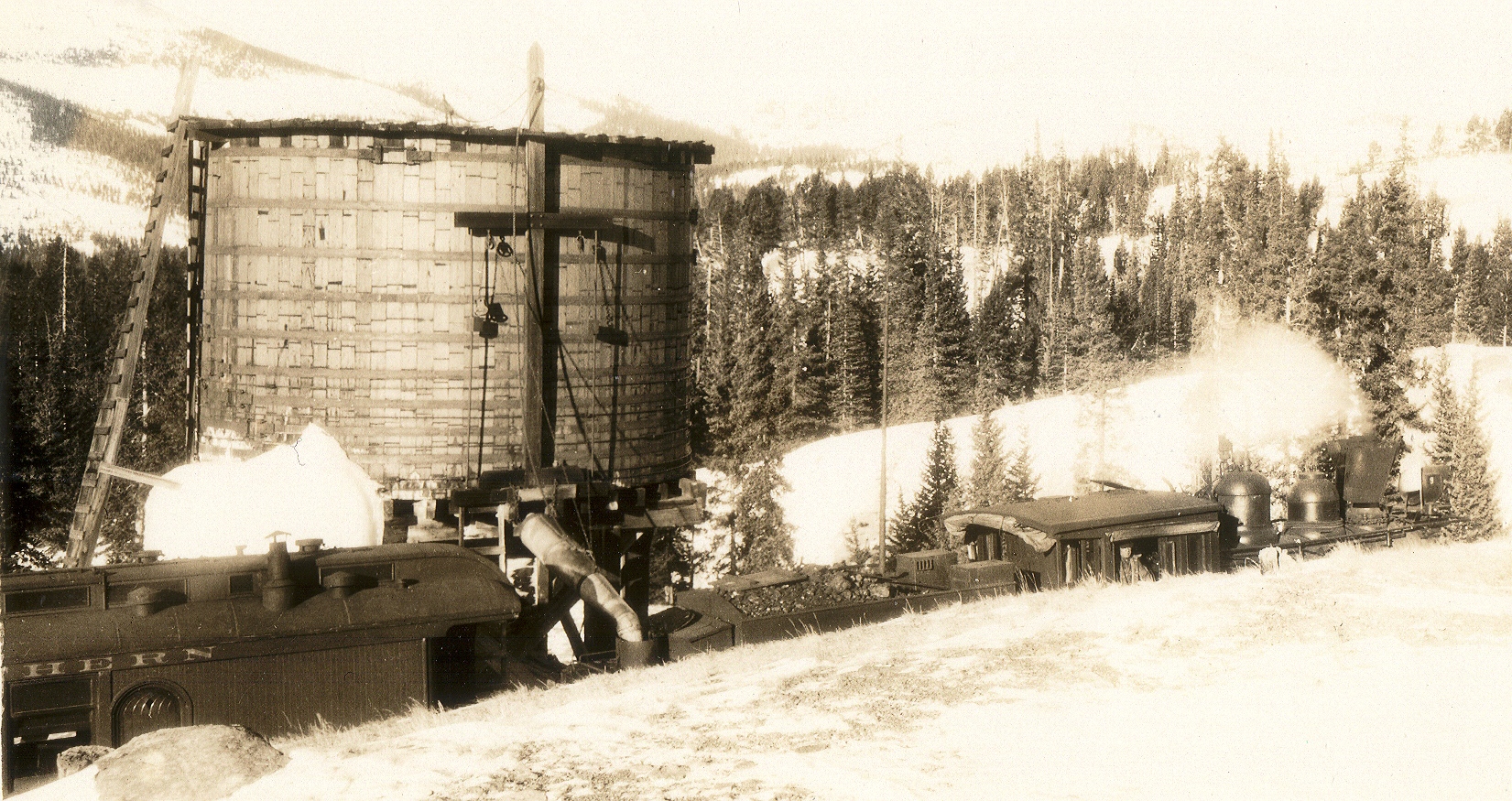 |
|
In reply to this post by Jim Courtney
Dare we include these with Locomotive Coaling Stations I wonder? Every Pumphouse would have to have a Coalsupply until I.C. replaced the Boilers. Otherwise we'll have to start including these as well .... Running Lode Mill, Blackhawk 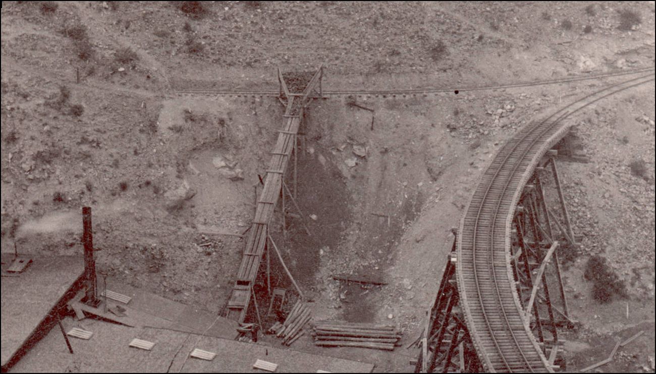 http://cdm16079.contentdm.oclc.org/cdm/fullbrowser/collection/p15330coll22/id/70218/rv/singleitem/rec/227
UpSideDownC
in New Zealand |
Ya' know Chris, until I saw that photo I had no idea what it was. Because of the way it was drawn on the map, my assumption was that it was a locomotive coaling station, not a coal house & chute for the pump house! Now I at least know what kind of structure it was, it's purpose, and a good idea of how to model it. |
|
So not Halfway Tank which was a little downgrade?
Trying to think where the water came from. |
|
Hi Tom,
This is a larger screen capture of the ICC Map Bob provided, along with the picture. I am pretty sure map is of Selkirk, as it also shows the trestle bridge. What do you think? 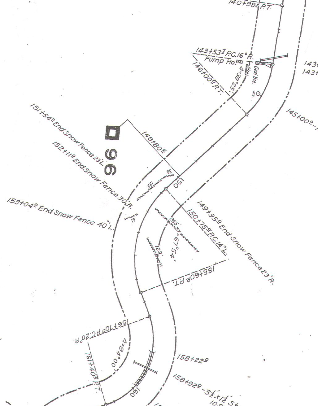
|
|
This post was updated on .
In reply to this post by Chris Walker
Chris wrote:
Dare we include these with Locomotive Coaling Stations I wonder? Every Pumphouse would have to have a Coal supply until I.C. replaced the Boilers.  My bad, Chris. My bad, Chris.
When I first looked at Don's map, I read the coal bin, chute and water tank as all uphill from the railroad grade. Now, it's obvious that the chute was to unload coal to the coal bin that served the pump house. Don, thanks for sharing the great photo of the water tank. You're right, it does seem to share the same dimensions as Baker Tank. Judging form the hardware on number 9 and the Business Car behind the thirsty tender, I would guess the date to be 1929, and this is the Denver Water Board inspection special. Who else would walk uphill during winter, just to take a photo of a water tank? A railfan would have likely framed the photo better to include the train. And just to complete the scene, here is a Perry photo from 1946, showing part of the Selkirk trestle that shows up on Don's map at the lower left corner: http://digital.denverlibrary.org/cdm/singleitem/collection/p15330coll22/id/44194/rec/3 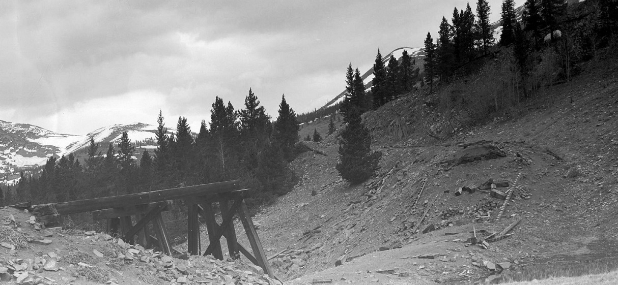
Jim Courtney
Poulsbo, WA |
|
In reply to this post by Don Pacetti
Don, Thanks for posting that brilliant photo. I'm looking at those Tank Staves as having been either reused from another Tank or reassembled after repair/replacement as the lines on the Staves appear to me to be marks from Tank tension rods. I can't see them butt-jointing wood back in thosedays of cheap and plentiful lumber.
UpSideDownC
in New Zealand |
|
The horizontal lines on the tank staves must be rust marks / indentations from previous tension rods. Even if they spliced timber together like that (and I agree that it’s hard to imagine), it wouldn’t hold water as a water tank (like a barrel) relies on the swelling of the wood across the grain to seal itself.
The trestle is also really interesting, as the foundation is a fill (with a box gutter in it, no less). What’s the structure marked on the ICC map between the coal house and the pump house? Cheers, Jeff. PS: I love the Selkirk water tank and the Blackhawk coal chute pictures! Thanks for posting.
|
Jeff, Writing says "Steps" The Boxculvert below the Trestle is interesting, is this the res. for the Watertank feedpipe perhaps? I haven't gone and checked the locality in relation to Grade or anything yet. My head is filled with Turntable construction problems at the moment and I don't want to disturb it 
UpSideDownC
in New Zealand |
Re: The C&S Coal Chutes: Four bins? Six Bins? Eight Bins? Twelve Bins?
|
In reply to this post by Jim Courtney
Here is the photo you requested and I promised. I'll ask Roper if he would be kind enough to post it to the blog, too. Model still needs some weathering and ground cover, but I think you get the general idea. 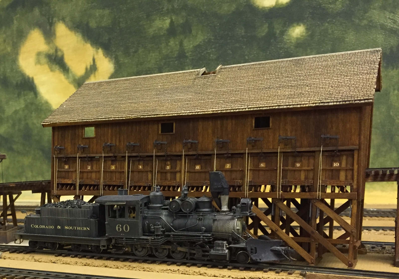
|
Re: The C&S Coal Chutes: Four bins? Six Bins? Eight Bins? Twelve Bins?
|
And another fine piece of modelling. (Nice weathering on #60, too.)
|
Re: The C&S Coal Chutes: Four bins? Six Bins? Eight Bins? Twelve Bins?
|
In reply to this post by Todd Hackett
New images from the FB Como Civic Association page.
https://www.facebook.com/ComoColorado/photos/pcb.470970626439553/470970323106250/?type=3&theater I think it captions "Engines on 71, Spring 192?. The Como coal chute appears to have doors that are shut on the shelter over the chutes. 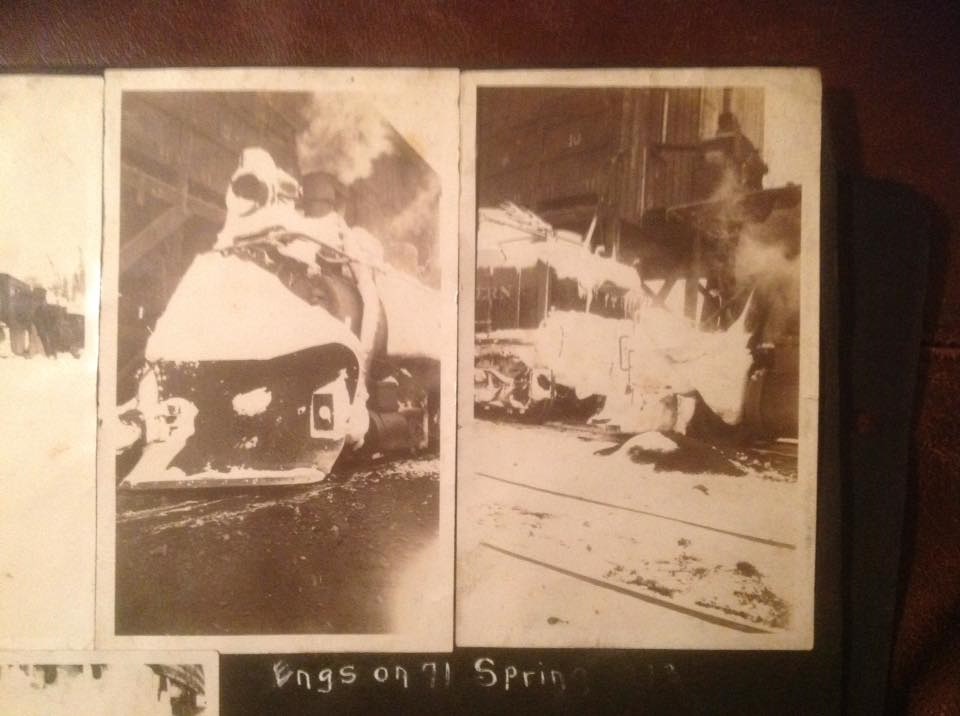
|
Re: The C&S Coal Chutes: Four bins? Six Bins? Eight Bins? Twelve Bins?
|
Nice find, Jeff.
I tried some digital reprocessing, but it didn't help much: 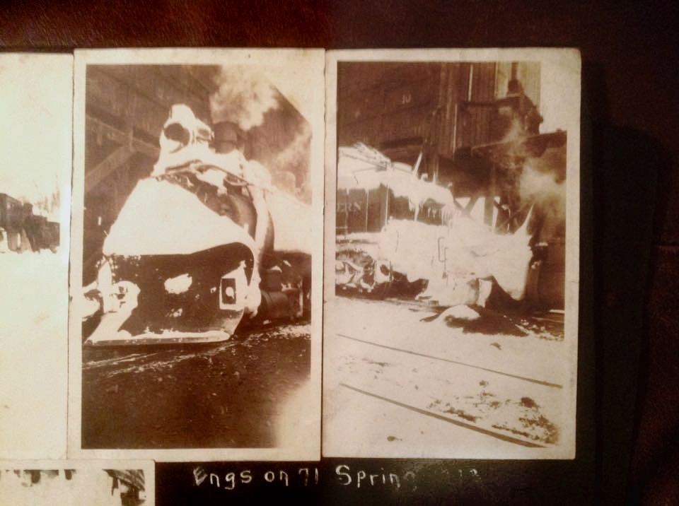
|
Re: The C&S Coal Chutes: Four bins? Six Bins? Eight Bins? Twelve Bins?
|
In reply to this post by Jeff Ramsey
Hi Jeff, Thanks so much for posting the second photo of the chutes; have never seen that one before! Bob Schoppe, David Tomkins and I are writing a comprehensive history of Como, with a lot of help from Tom Klinger. Based on our research we believe you are correct; however, the photographic evidence indicates only the north end of the shelter had the doors. Considering the chute's shelter was oriented north-and-south, and the prevailing winter winds Como, that is not surprising. |
Re: The C&S Coal Chutes: Four bins? Six Bins? Eight Bins? Twelve Bins?
|
I thought this thread should include at least one photo of a C&S locomotive on one of the coaling trestles:
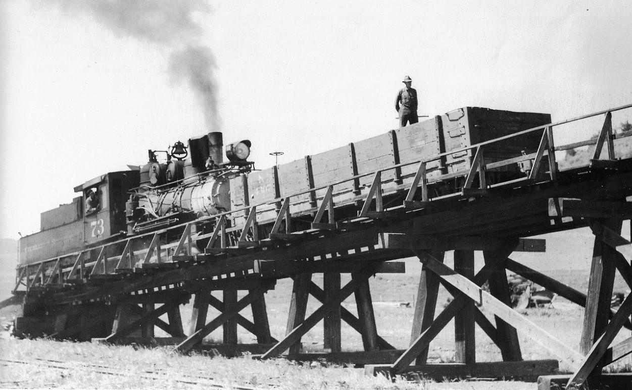 Richard Kindig photo, Como, July 31, 1938, in Poole and Martin, Narrow Gauge Pictorial volume VIII, page 71.
Jim Courtney
Poulsbo, WA |
|
In reply to this post by Jeff Young
Hello all,
Have just joined the group, first question - is there a plan of the como coal chutes , or have those who have built one worked out their own using photos and probably Joe Crea's plan and modifying for the best to fit the photos. I have Joe's plan and have built one using a Crystal River kit and modifying it in HO. This time it will be in S and will only have 6 bins, I have made rough plans but would like to know if there better around. The reason for only 6 bins is space to fit on a 1.1m portable section, so will be a steep trestle section. Thanks for listening, Paul R Ballarat, Vic.AU. |
Re: The C&S Coal Chutes: Four bins? Six Bins? Eight Bins? Twelve Bins?
The Como chutes are very different from the Dickey, Pine Grove, or Pitkin chutes. The Joe Crea drawings were based largely on original C&S plans for Pitkin and photos of others, and is a fairly generic representation of a typical C&S coal chute except Como. I drew the Como chutes probably 30 years ago from folio data and photos. As I gained access to more photos, I began to make some corrections, but never finished. I scanned it a while back, and several people have used it to build models. Here is the main front view: 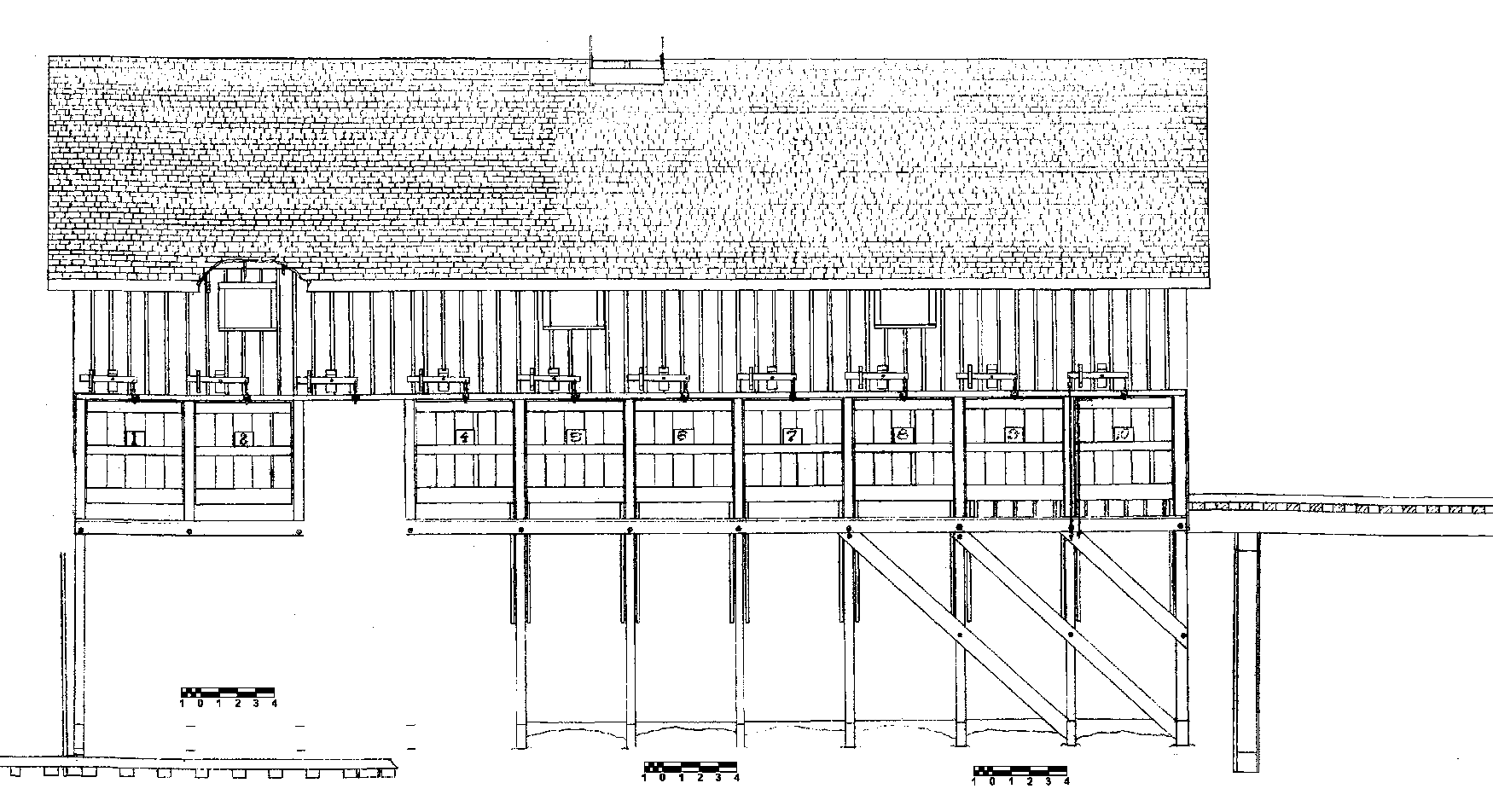 |
|
Hello Todd,
That saves me,I now can check to see if my drawing is out . I made a lot of surmises, I assume that is board and batten siding, and the shingle roof is about 8inches cover, many thanks for a copy of the drawing. Paul R. On Sat, Feb 20th, 2016 at 1:16 PM, "Todd Hackett [via C&Sn3 Discussion Forum]" <ml- [hidden email]> wrote: > > > Paul R. wrote > > ...is there a plan of the como coal chutes... > > The Como chutes are very different from the Dickey, Pine Grove, or Pitkin > chutes. The Joe Crea drawings were based largely on original C&S plans > for > Pitkin and photos of others, and is a fairly generic representation of a > typical C&S coal chute except Como. I drew the Como chutes probably 30 > years > ago from folio data and photos. As I gained access to more photos, I > began > to make some corrections, but never finished. I scanned it a while back, > and > several people have used it to build models. Here is the main front view: > <http://c-sn3-discussion-forum.41377.n7.nabble.com/file/n4841/ComoFront.png> > > > > > > _______________________________________________ > If you reply to this email, your message will be added to the discussion > below: > http://c-sn3-discussion-forum.41377.n7.nabble.com/The-C-S-Coal-Chutes-Pine-Como-Dickey-Pitkin- > > To unsubscribe from The C&S Coal Chutes: Pine, Como, Dickey, Pitkin and > almost Breckenridge, visit > http://c-sn3-discussion-forum.41377.n7.nabble.com/template/NamlServlet.jtp? macro=unsubscribe_by_code&node=4269&code=cHJpY2hpZUB2aWMuY2hhcmlvdC5uZXQuYXV8NDI2OXwx MjYxMTM0NzMx |
«
Return to C&Sng Discussion Forum
|
1 view|%1 views
| Free forum by Nabble | Edit this page |

