Leadville Designs Baggage/Express 1 in C&Sn3

123

123
Leadville Designs Baggage/Express 1 in C&Sn3

|
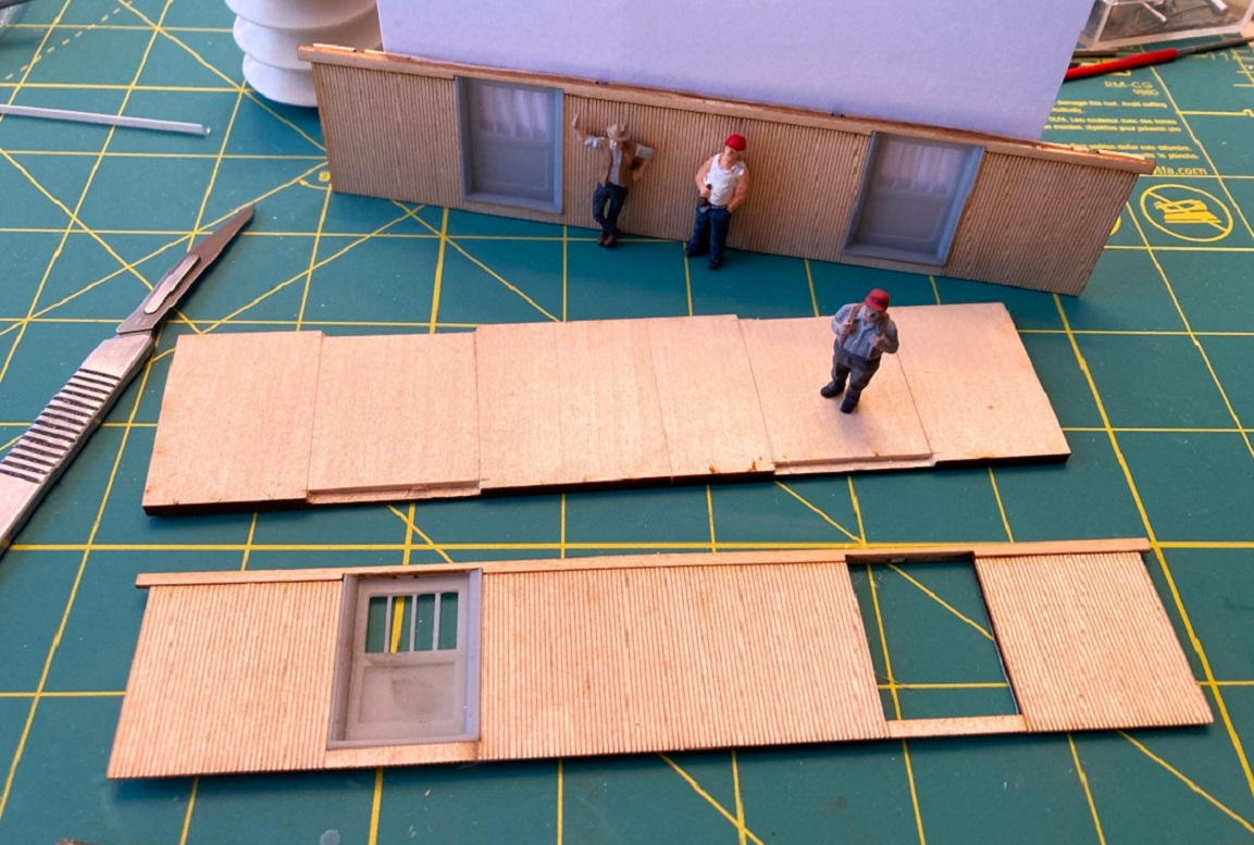 I couldn't make it to the NNG convention, so I couldn't pick up my baggage car kits and trucks as did Keith and others. But the USPS left a package from Canada on my front porch yesterday. The cast brass trucks are neat, as Keith has reviewed, but my attention went straight to the baggage car kit. I was surprised and impressed that this Co-Op project turned out so well. Bill has produced a clever kit with an eclectic mixture of materials: Lase cut parts for the body, beautifully rendered resin prints for the major parts, brass and nickel-silver etchings for all the details, and the 5'-6" trucks to make it perfect. Of course, I started building the kit last evening. The instructions say to begin by building up the roof. But as I suffer from clerestoryroofaphobia, I decided to build up the sides first to build up my confidence. The sides consist of an inner wall with door cut-outs, and outer very thin (1/32") layer, laser engraved with the sheathing, and a laser cut fascia board. The fascia is glued to the top of the inner wall first. I used Titebond III carpenters glue as it has a bit longer working time to line up things perfectly. I used my Fast Tracks assembly fixture as a thick straight-edge, to keep the top of the fascia board and the top of the inner wall flush. The sheathing overlay is very fragile, I broke one of the horizontal planks (below the door), was able to repair it. When the overlays had been glued down, I let the wood components dry, under weights, overnight. Today, I added the doors. I had dreaded building up 8 pieces of quarter round and trim to frame the doors, but Bill again surprised me with four beautifully detailed side doors as resin prints. When the door openings' sides and tops have been sanded flush, and the corners all squared up, the doors fit into the openings perfectly. I did have two issues with the doors. Each door has two little side tabs, to allow the doors to be glued to the inner walls. These little tabs are a bit over 0.040" thick. When the doors are inserted into the sides, the vertical trim of the side quarter-round framing are pretty much flush with the side sheathing. IMHO, they and the door threshold should protrude from the sides a bit. So I used a 6" pillar file to carefully fill down the out side surface of each tab (the gluing surface) so that the tabs were only 0.030" thick. With the doors now inserted, the vertical trim and the door threshold now protrude about a scale inch from the sheathing:  The other issue with the doors is an oversight on Bill's part. The top of the printed threshold of each door is meant to be even with the top of the floor. But the sides are supposed to be attached to the floor by gluing the strip of exposed sheathing to the side of the floor, while the bottom of the inner wall sits atop the floor and is glued. The printed door threshold intrudes into that space, so that the side sheathing will not be flush with the bottom of the floor. The solution was to use my razor saw and a new #11 scalpel blade to cut notches into the top of the floor to clear the doors (see title photo). Here are the two sides built up: 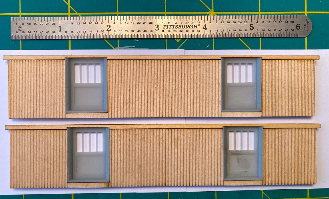 While the next step is attaching the sides to the floor, I decided to build up the ends next. The wood components are the same as the sides: Inner wall, thin outside sheathing, and top fascia board. Very clever Bill Meredith designed a one piece resin print of the end doors and end beams: 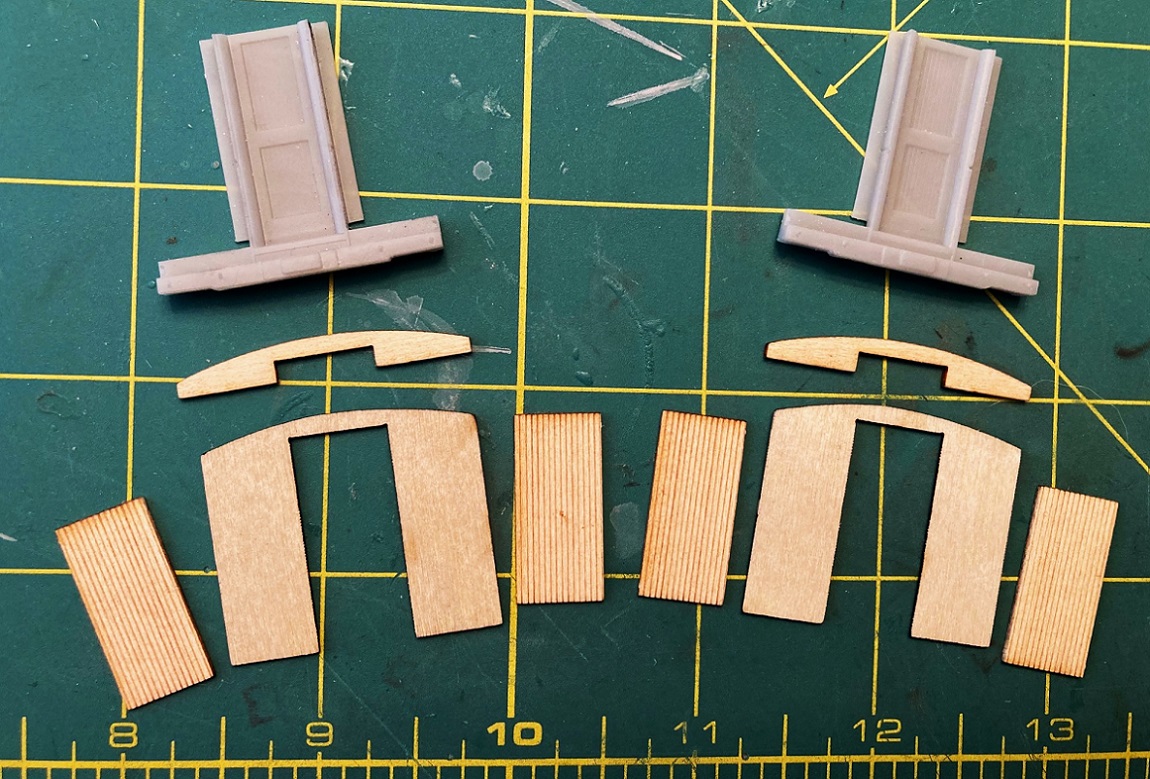
I'll keep you posted as I make progress. All you HO and O scale builders of baggage car 1, please post photos of your work and discuss any construction issues you encounter as well as your solutions. We C&S model builders now have baggage cars! _________________ I'm stretched thin with several C&S projects abuilding at once. So I hired a crew of Keith's little people and flew them up from Denver to assist in this project. They're a rowdy bunch, but if one supplies them with plenty of S-scale beer they work hard and are friendly folks . . .
Jim Courtney
Poulsbo, WA |
Re: Leadville Designs Baggage/Express 1 in C&Sn3
|
|
Hey! Don't get those little guys too liquored up! Feed them coffee. Lots of black coffee!

Keith Hayes
Leadville in Sn3 |
Re: Leadville Designs Baggage/Express 1 in C&Sn3
|
|
This post was updated on .
A bit of progress on Baggage 1:
Building up the ends was to have been straight forward, save a design flaw: 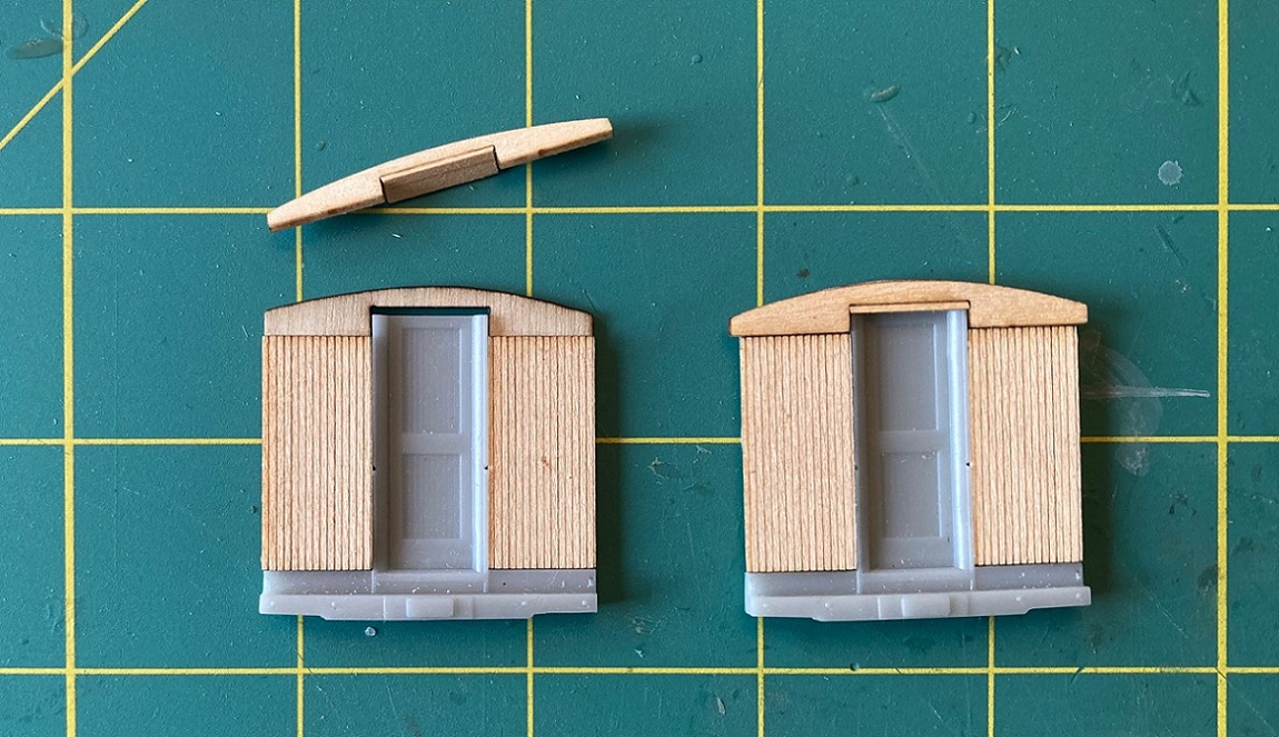 The door cut out on both the inner wall and the fascia board were cut too tall, leaving about a 2 scale inch gap at the top. I cut scale 2x6 to the width of the cutout in the fascia board and filled the gap. I'll probably use putty or plastic wood to fill the seam. Attaching the sides to the floor ought to be simple, but it gave me fits. The floor isn't rigid, cut from basswood with the grain running the width of the floor--it tends to bow in the middle or lift up at the ends. The two gluing surfaces are about 1/8" of very fragile outside sheathing that glues to the outside of the floor and about 1/16" of the lower edge of the inner wall, that glues to the top of the floor. The side have to be aligned with the floor so the ends of each are flush. This required downward and inward pressure on the lower floor until the glue sets up. I couldn't figure a way to clamp the sides to the floor. I ended up using all my FastTrack point form tools, and machinist squares to hold things together: 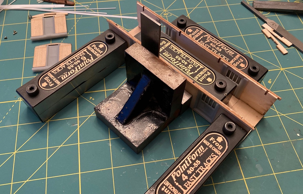
Anyways, (as Keith would say) with much heavy breathing, I got both sides glued to the floor, pretty much at a right angle to the floor with the lower sheathing edge flush with the floor bottom. There must be a better way to do this, bar-clamps perhaps--or those magnetic plates with magnets to hold things together when assembling structures. Since the baggage cars will have no visible interior, when I build the second kit, I'll likely glue strips of 1/8" square wood to the inside of the interior wall, flush with the lower edge of the interior wall, for a larger gluing area that can be weighted. Since my Leadville Designs coach 62 has the same assembly sequence, not sure what I'll do there and have a full interior. Anyone have a better idea? When the glue was dry and everything looked OK, I added the top joists to strengthen the basic car body structure: 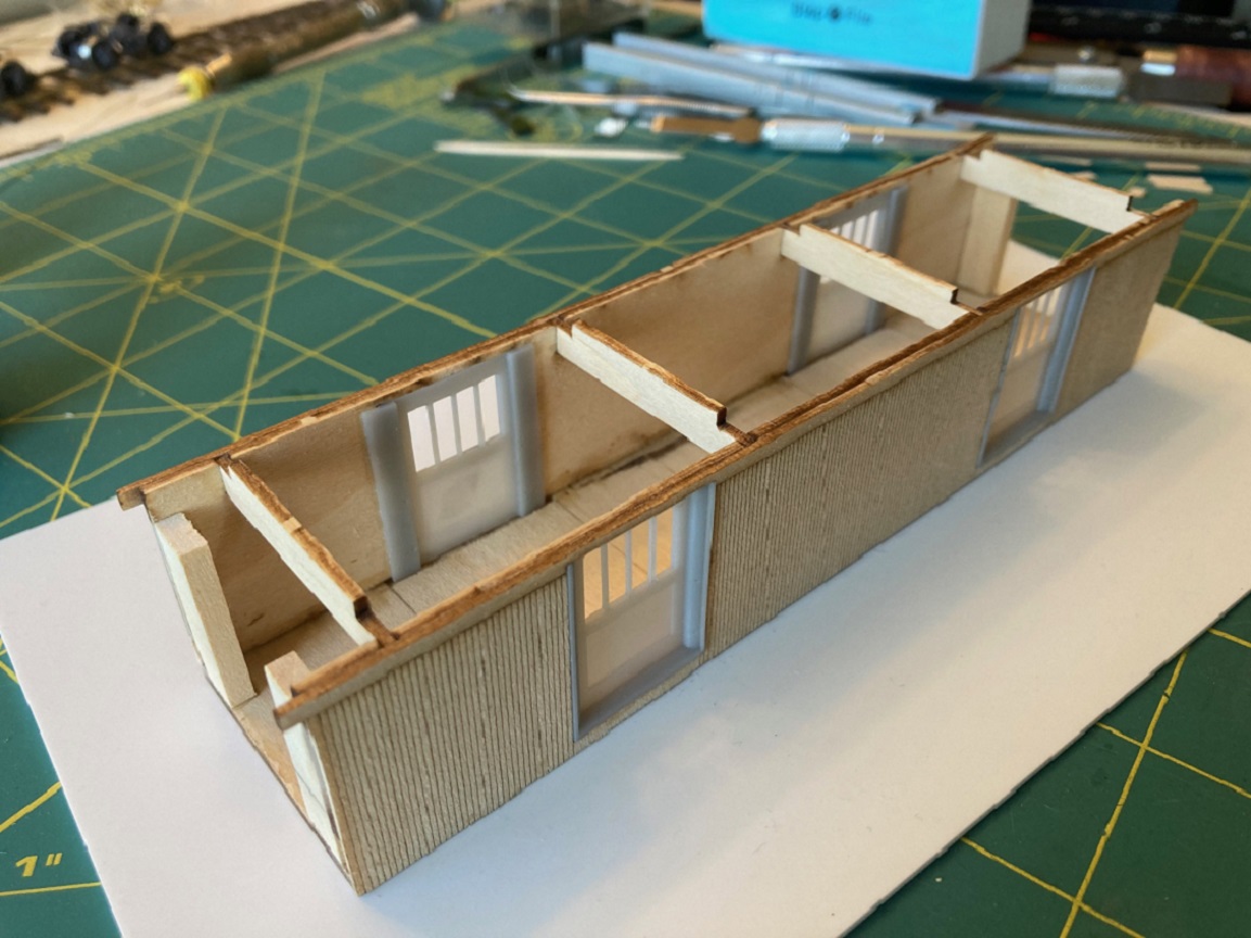 The raised tabs on the joists evidently interlock with the clerestory roof (that I haven't yet built). The pieces as cut don't fit in the slots without spreading the sides apart at the top--they're not too long but too thick (or the slots are too narrow). I sanded the width down until they seated squarely in the slots and made sure the distance between the inner walls was the same from bottom to top. Forget about the two pieces that fit at the lower ends of the side--the notch in them is too narrow to clear the back of the printed end doors. Instead I cut 1" lengths of 1/8"x5/8" strip wood and glued them to the floor and the inside of the interior wall, flush with the ends of the sides/floor. This will provide a gluing surface when the ends are attached. I test fitted one end and found that they line up vertically just right: 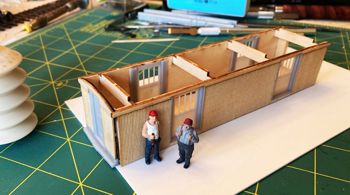 The printed quarter round needs to be installed before the ends can be permanently attached. While I've got the two end on the flat, I think I will drill some holes and add some details first . . .
Jim Courtney
Poulsbo, WA |
Re: Leadville Designs Baggage/Express 1 in C&Sn3
|
|
Jim time to exhale and enjoy a pint with the fellas while staring at something a ways away.
Keith Hayes
Leadville in Sn3 |
Re: Leadville Designs Baggage/Express 1 in C&Sn3
|
|
This post was updated on .
In reply to this post by Jim Courtney
Jim, beautiful work and thanks so much for these step-by-step-with-gotchas accounts of your expericence.
I just received three of Leadville Designs new HOn3 B&S D&RG boxcars (heck, they are documented on the South Park during the Leadville boom so I had to have a few--that's my excuse) and after looking at the very delicate walls and other bits I was stopped in my tracks. These aren't for the faint of heart! But you've given me confidence to screw up the courage to tackle these. Thanks!
Dave Eggleston
Seattle, WA |
Re: Leadville Designs Baggage/Express 1 in C&Sn3
|
|
Hey Dave,
I hope my project is helpful for you and others building Leadville Designs wood kits. By all means, press on with your B&S boxcars project--and maybe start another thread to share your progress. Having built a couple of Bill's 1898 boxcar kits, I highly recommend that you do a "test build" of one kit first, from start to finish, and keep notes of problems encountered and your solutions. Then batch build the remaining two kits at once. I'm learning that these wood kits require about 15-20 minutes of work at each step, followed by several hours of glue drying. I assure you that construction problems will be encountered, parts that don't fit and have to be modified, or replaced with strip wood. Be aware of the phenomenon of "laser bevel". Laser cuts in wood have a slight bevel on the cut edge. With thin pieces of wood, like the side sheathing, this is negligible, but with thicker pieces, like underframe sills or those protruding end beams on the J&S boxcars, the bevel can be significant. Instead of the pieces having a rectangular cross section, it's more like a trapezoid. I sand the pieces square with my NWSL "True Sander", using a small drafting square as a fence. In some cases it makes more sense to replace the laser part with very square strip wood, or even styrene strip. Geoff Hamway has built many a Leadville Designs boxcar kit for his first-decade RGS layout, including several B&S boxcars from the same kit, albeit in S scale. Perhaps he can opine and give you some construction advice on these cars. _____________________ Meanwhile, as to the baggage car project, I'm confronting my irrational fear of clerestory roofs and have spent the last few days working on the baggage car roof. Perhaps a progress update with photos tonight or tomorrow, depending on the glue drying . . .
Jim Courtney
Poulsbo, WA |
Re: Leadville Designs Baggage/Express 1 in C&Sn3
|
|
Clerestory, clearstory!

Keith Hayes
Leadville in Sn3 |
Re: Leadville Designs Baggage/Express 1 in C&Sn3
|
|
In reply to this post by Jim Courtney
Dave,
I guess that was my cue to chime in on the B&S box cars kits. As Jim said, I've built a half dozen of the Sn3 kits, and they build up into nice models without too much effort. The S & O scale kits are 10 years old now, so one would hope that some of the design glitches in the older kits have been corrected in the new HOn3 models. Still, I can make a few general suggestions to add to Jim's: Unlike many of Bill's newer kits, the B&S box cars included beautiful plans by Bob Stears -- if good plans aren't in the HOn3 kit, be sure to get some, because you'll need them. Also, the older kits included some self-adhesive parts (outer roof, fascia, etc.) that caused me considerable heartburn. They seem to adhere properly, until AFTER you've painted, lettered, weathered, etc., and THEN they can start to lift up. I quickly learned to replace these parts entirely or scrape the self-adhesive film off and glue them normally. The kits (including the new HOn3 ones, I believe) include a detailed interior and roof structure. Plan ahead to add sufficient weight where you won't see it, and be VERY careful when you install the lateral carlines -- these can very easily make the side walls bulge out of alignment and you may not notice until you've glued the roof on. The older kits included brass etchings for the distinctive B&S step/grabs on the B end. These weren't accurately designed and only Spiderman could have gotten up to the brakewheel using them. Hopefully the HOn3 ones match the prototype better, but I felt obliged to build new Sn3 ones from styrene (although they're small enough that I might not bother in HOn3). One final general tip. I prime the exterior plywood pieces with a rattle can primer or even Dullcote before assembly. I airbrush later with acrylic paints, and I've had occasional problems with them raising horizontal grain swirls on the plywood. Very unprototypical looking, and a pain in the butt to cover up. I hope you'll post your experiences with the new HOn3 kits. Good luck with them, Geoff Hamway |
Re: Leadville Designs Baggage/Express 1 in C&Sn3
|
|
This post was updated on .
Okay, back to the C&S baggage car project -- some progress to report.
Before installing the ends, prep work for installation and future detailing was done: The back surface of the printed end beams are not flat, rather have a wavy, irregular surface due to some artifact of resin printing (perhaps Steve Guty or Roy Stevens can 'splain it to us). Using a 6" pillar file the back of the lower print was filed flush with the back of the interior wall. Flipping the ends over, holes for mounting the inverted L-shaped end grab irons were drilled (Bill printed dimples to mark the location, 2 on the vertical door frames, and two on the lower sheet metal below the door, near the edge of the ends). The end beams have dimples for mounting two 17" drop grabs. These were drilled #80 and the drop grabs were formed and installed. Using Ken Martin's plans and photos, the location of the horizontal brake staff, for the big brake wheels was located and drilled #76. Short pieces of 0.019 wire were installed as locators. Tiny lengths of 0.008 wire were installed just a smidge to the left of the brake staffs to hang the brake chain. Lengths of chain were hung from the little wire vertically and the point that they touched the end beam was marked. The holes to allow the chain to pass through the end beams were drilled up from the bottom. starting with a 0.015" drill, gradually enlarging to a final drilling of 0.035", to clear the chain. One end was the designated "B" end and a #80 hole was drilled for the retainer pipe. These tasks will simplify adding details to the ends later: 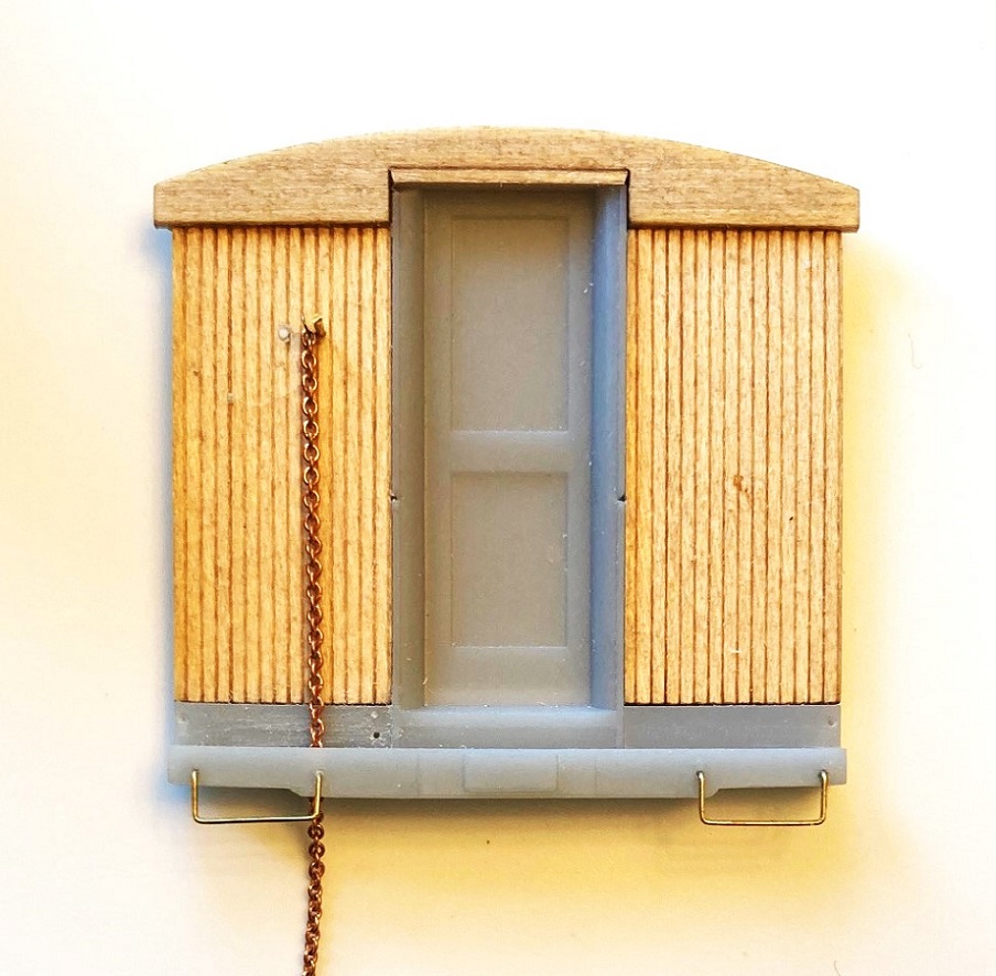 The two ends were glued to the gluing blocks installed on the car body, lining up the bottom of the end fascia with the bottom of the side fascia. When everything looked vertical, I used ACC to secure the lower resin printed parts of the end. I ended up not using Bill's printed quarter round trim, as: --Not all were straight. --They are too long, need to be trimmed at the top to fit (the ends without grab iron dimples) --I broke one in several places trying to get it off the stem to the print raft (correct terms, Steve?). Resin sometimes shatters when cut. So, I made my own quarter round trim from Evergreen styrene 0.060" quarter-round, using HO scale 2x6 and 2x8s for the vertical straight trim. When cut and filed to length, they were glued into place at the corners with Gorilla ACC gel: 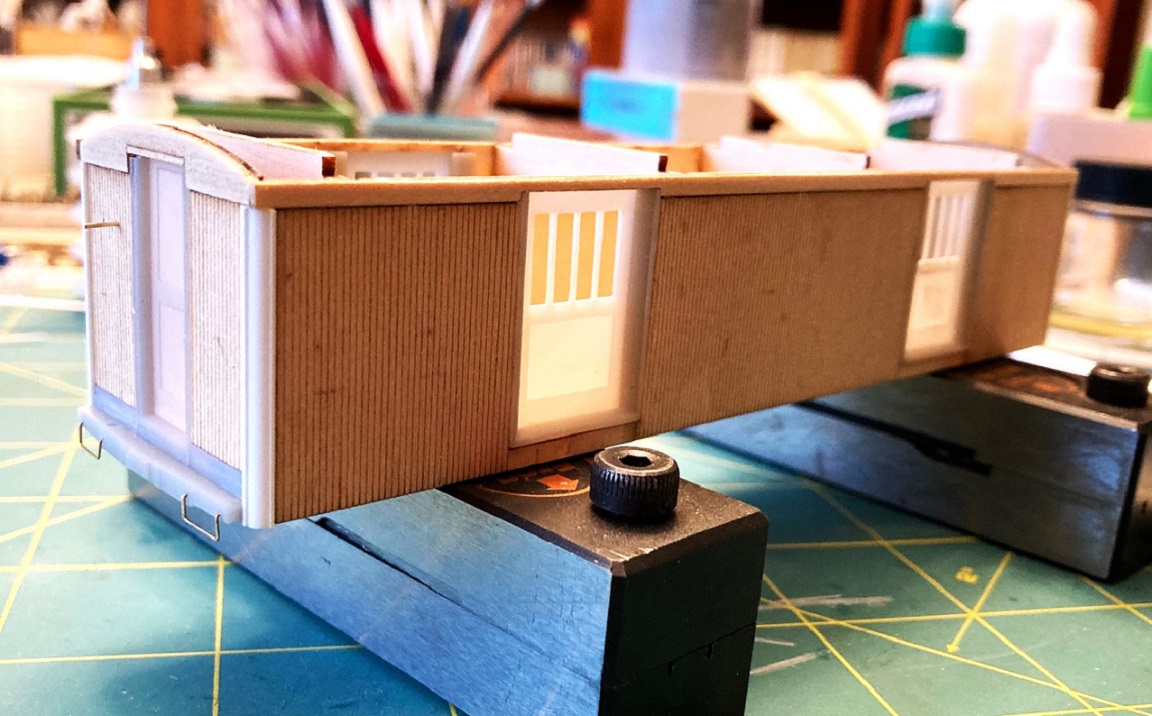 Now for the scary part, building the clerestory roof. The roof framing consists of six laser cut profile ribs, an upper sub-roof and two notched side rails. Four of the ribs are glued to the underside of the top sub-roof, using a machinist square as the glue set. to make sure each is square. The little tabs at the top of the ribs protrude above the sub-roof a bit--don't sand this down, as they provide support for the gentile curving top roof panel later. 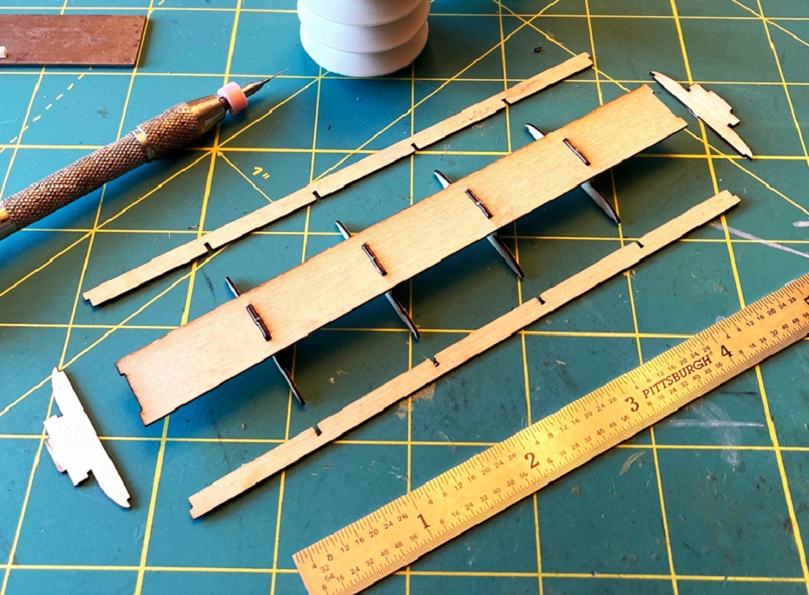 The two notched side rails were glued to the four ribs next, one at a time. The instructions say to use the included alligator clamps to clamp each joint, but I found that they distorted the joint. Instead, I used a weight from above: 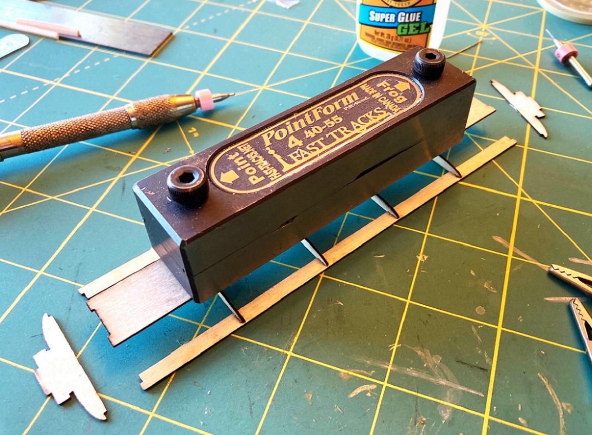 When the side rails were firmly dry at the joints, the two end profile ribs were added. This is how the clerestory roof framing looks atop the car body. The upper tabs on the car body joists keep the roof framing lined up and centered over the length of the car body: 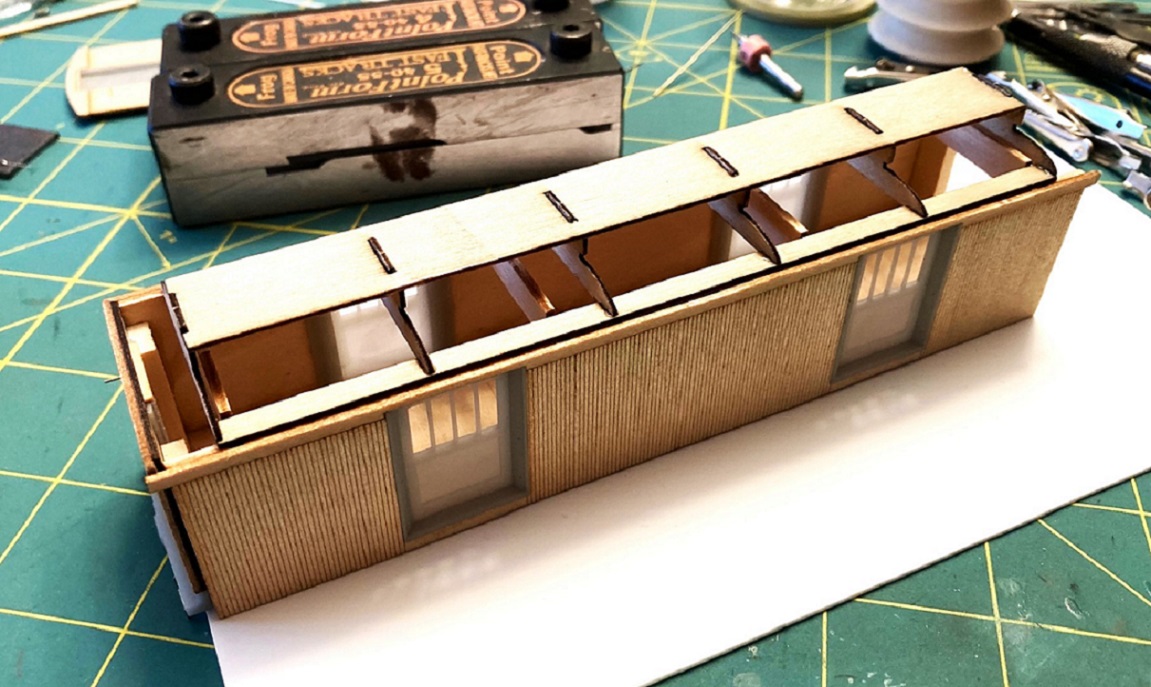 Time now to add the lower clerestory roof panels. Examining the parts, I noticed some wood fuzz on the surface, Rather than sanding it and creating more fuzz, I removed the three roof panels from the fret, dressed the edges and gave the outer surfaces a couple of coats of Testors Dullcote from a rattle can to seal the grain (the underside of each piece, with the laser scribed bending lines were left raw wood for gluing. When dry, the tops of each panel were sanded until smooth. Before adding the lower roof panels to the frame, one at a time, the instruction advise covering each top surface with masking tape, just short of the little notches, presumably to keep them from getting marred by alligator teeth in the next clamping step. The notched edge of the side panel is inserted into the glue filled notch in the framing ribs (and a little glue on the ribs next to the notches and clamped into position until dry, repeating the process on the other side: 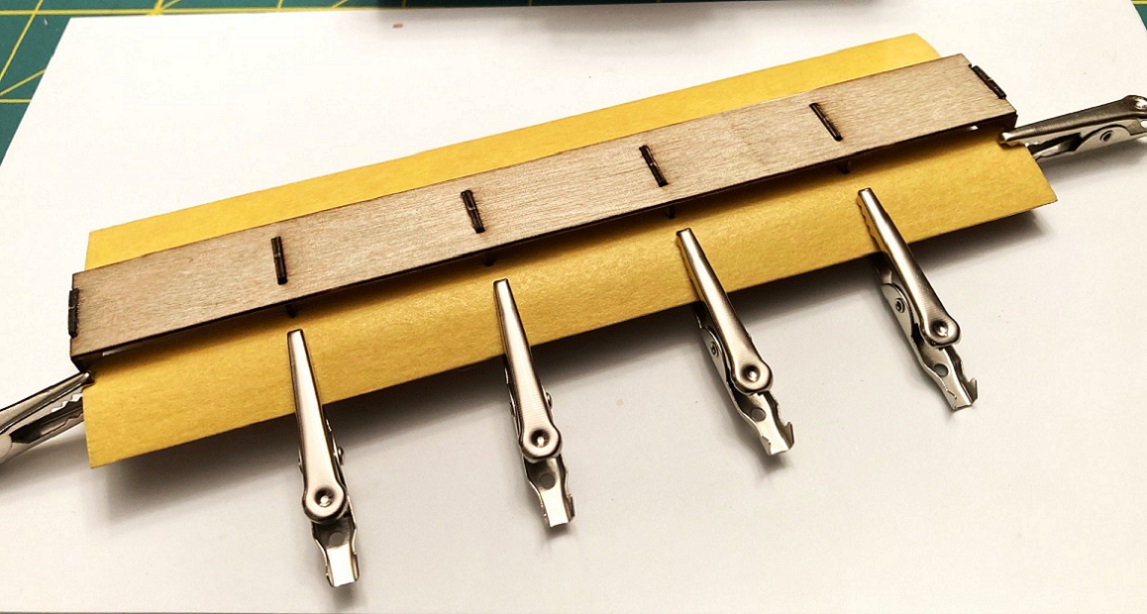 When this joint at the notched ribs is completely dry (overnight), liberal amounts of glue are applied to the remainder of each rib and the sides of the side rails, and clamped. I used the Micromark accordion glue applicator with the 20 gauge blunt needle to reach up under the roof panel to apply the glue to the ribs: 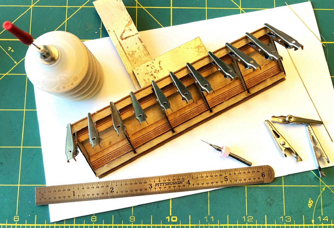 I have two kits, so I doubled up on the alligator clamps. Note that the lower roof panel rolls down past the bottom of the side rails, nearly an 1/8 inch--this will have to be sanded flush later. When the glued roof panel had dried overnight, I removed the clamps, and reinforced the joints with the roof ribs and side rails with a bead of thin ACC. The same process was used on the opposite lower roof panel, letting the glue dry overnight. Lots of glue drying going on here! With the masking tape removed, this is how the clerestory framing with the lower roof panels installed looks: 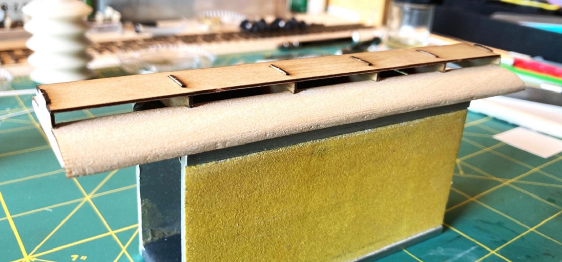 As there are visible alligator bite marks, the masking tape didn't seem to do its job--maybe two layers would work. Will have to fill these bite marks with putty, if still present after the next step. Next up, I'll get a fresh piece of 800 grit sand paper, lay it flat on the hard, flat surface of the quartz kitchen counter tops and gently sand off the protruding roof edges back until they are flush with the bottom of the side rails and ribs; that is, the entire bottom of the roof assembly, so far, needs to be a perfectly flat plane, We will see how this all turns out next time . . . 
Jim Courtney
Poulsbo, WA |
Re: Leadville Designs Baggage/Express 1 in C&Sn3
|
|
This post was updated on .
In reply to this post by Geoff Hamway
Wow, Jim and Geoff, when I posted I hadn't been expecting to get such great feedback; I just thought the thread of great value by itself! Thanks so much for sharing and the helpful tips.
The HOn3 kits don't include plans. I have copies of the original B&S plans stored at DPL's archives, plus plans of other B&S cars (I've been very into the Nevada Central's B&S cars for a long time). I don't think I have Stearns' plans in my files. I had planned to keep the doors closed which solves a few issues, like weight placement. I need to look at the end steps to see how close to prototype they are. Even on the prototype these were not Spiderman-friendly! Paul Scoles and I used to talk about why no one ever modeled early RGS, it had great equipment and great operations. Nice to see someone doing it.
Dave Eggleston
Seattle, WA |
Re: Leadville Designs Baggage/Express 1 in C&Sn3
|
|
In reply to this post by Jim Courtney
Houston . . . we have a problem.
 Turns out, my fear of building clerestory roofs is not irrational, prescient perhaps. I finished sanding the roof assembly for baggage 1 yesterday and then did a test fit to the body. To my dismay, the roof is narrower than the car body. Not by much, but noticeable. My first thought was to narrow the car body over the letterboard fascia. I used small rectangles of 0.005" styrene to protect the sheathing from being marred by sanding, then sanded the upper letterboard flush. The letterboard now protrudes from the sheathing by only 0.005" or 1/3 a scale inch. The roof is still too narrow: 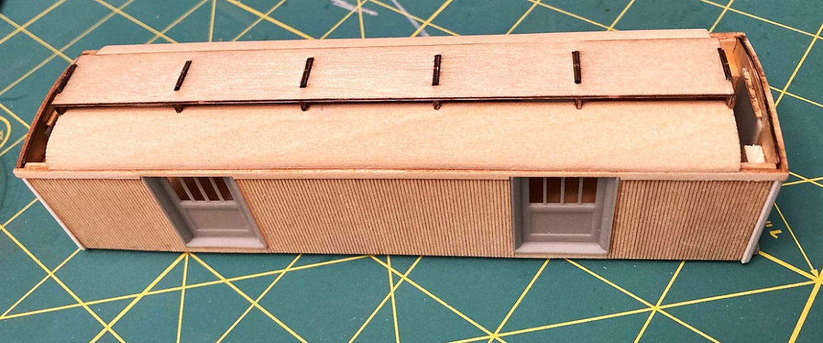 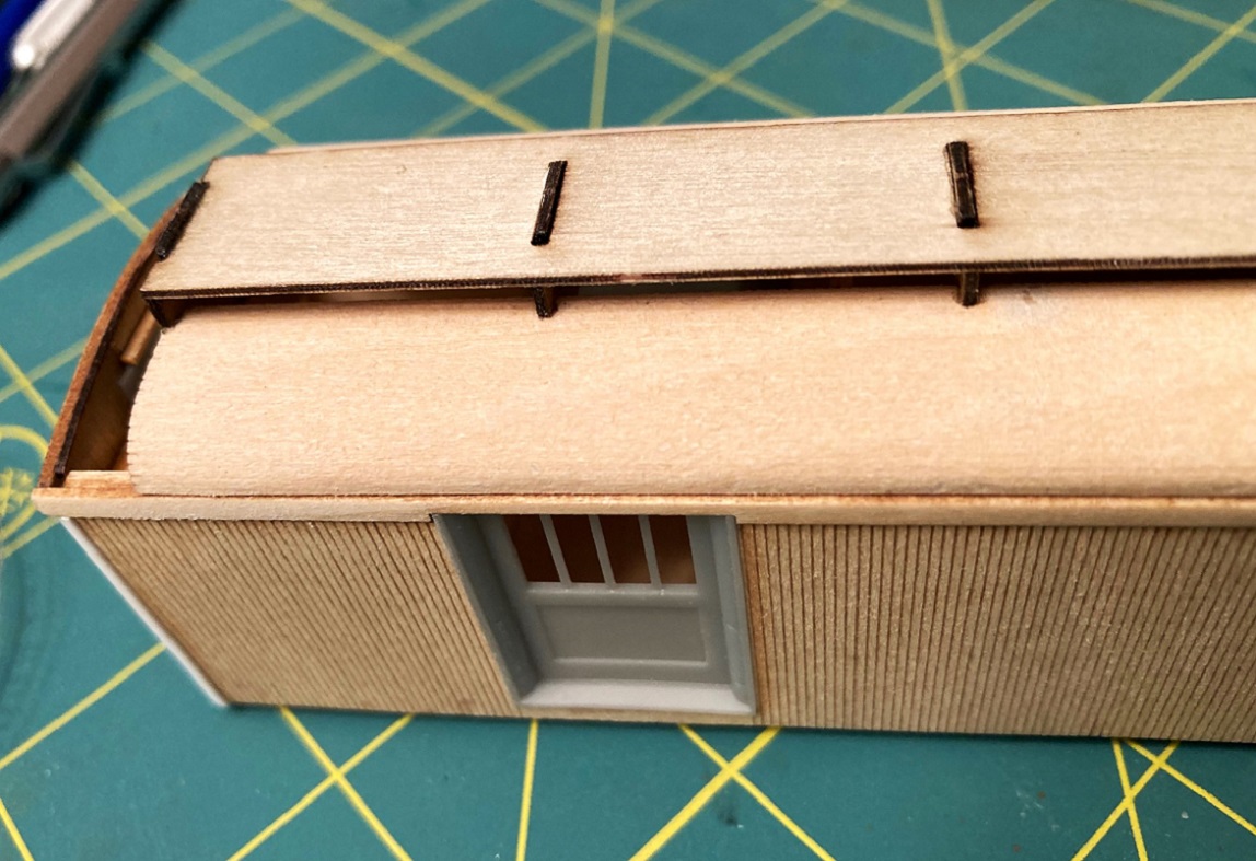 The roof should overhang the letterboard by at least a scale inch (0.015"). Mr. Micrometer tells me that the roof is 0.030" narrower than the body over the letterboards. If I want overhang as in the prototype photo, the roof needs an additional 0.030" of width. So, to be blunt, the roof as designed is 0.060" too narrow. So, folks, I'm stuck. I guess that I could press on as is, learn to live with the roof width problem and hope the final paint coat of dark green makes it less obvious. But being an O.C. kind' guy, I don't want a baggage car model that's just "pretty Okay". I would welcome any suggestions how to fix this . . . anyone? Having thought about it overnight, I did purchase two kits, so I could: 1. Abandon the car body as built to date, use the parts in the second kit and build a new body up, but symmetrically narrow the floor and ends by 0.060" (i.e. sand 0.030" off each side of the floor and ends. For those of you that have not started building this kit, this may be your best bet to avoid this problem. But at this point in construction, this option isn't palatable to me. 2. I will probably try the opposite: Put this incompletely built roof aside for future use (with a narrowed body). Use the roof parts from the second kit to build up a new roof framing piece, but before adding the lower roof panels, build up the width of the frame at the side rails by 0.030"--glue a strip of S scale 2x3 to the side of the side rails and then try to sand the upper edge so it matches the contour of the roof ribs. The lower roof panels seem to be wide enough to cover this buildup when rolled over, clamped and glued, as in the last two steps in the above post. ____________________ Please note that I discovered this design problem in the S scale kit. I have no idea whether the same glitch is present in the HO and O scale kits. But you folks should check before you start gluing pieces in place! And what about Bill's other passenger car kits, the Pullman sleepers, Pullman coaches and C&S coach 62? Does the same issue exist there. I don't know yet, haven't got that far. Out of curiosity, I measured the floor pieces for the Baggage 1 and Coach 62 kits in S scale. The Pullman floor is about 0.085" (about 6 scale inches) narrower than the baggage car floor. So there may be no problem there. But I don't know how thick the final build up of the coach walls will be . . . I'm going to put this project on hold for a week or two, so as to clear my head and rethink things, before cutting and gluing new parts together for a new roof. And in the meantime, hope one of you comes up with a genius solution for an easier fix for this dilemma. 
Jim Courtney
Poulsbo, WA |
Re: Leadville Designs Baggage/Express 1 in C&Sn3
|
|
Jim,
I can only commiserate with you....  I'd slice, sand or mill those edges, and laminate an additional strip on to each side then reprofile to get your overhang...all while hoping it doesn't blow out any other dimension in marrying the roof structure correctly. Or just smash it and start again. 
UpSideDownC
in New Zealand |
|
|
Jim,
How about checking with Bill M he might send a replacement with an adjustment.! I would go with adding a strip to each side then reprofile. Paul R. |
Re: Leadville Designs Baggage/Express 1 in C&Sn3
|
|
In reply to this post by Jim Courtney
Sincere condolences, Jim. I completely agree with Paul about throwing the problem back to Bill. At a minimum you should get a new set of roof parts. But it makes sense that he should re-engineer them correctly and send revised parts, rather than leave it to you and every other purchaser to correct for his error.
Geoff Hamway P.S. Is the inside fit of the roof good or does that need adjustment also? |
Re: Leadville Designs Baggage/Express 1 in C&Sn3
|
|
In reply to this post by Jim Courtney
Jim, I always appreciate you having a prototype image close at hand. I need to do better at this myself. I have and idea for you.
Studying your roof build, it strikes me that in section the contour rolls down such that the face of the roof almost flows into the side. Rather like a half sphere resting on a cylinder. Looking at the prototype photo the roof arcs and rests atop the side such that the face does not align with the side. I believe you have an opportunity correct the profile: place a strip of fine sand paper on your roof and sand a 1/8" square piece of basswood to the profile of the existing roof. Then glue the basswood to the roof edge and sand the exposed face to the correct profile, using filler as necessary. Your might consider finishing the ends first so that the profile will be continuous across the length of the car. I appreciate Bill's efforts to develop the kit and dp most of the hard work for us. Errors like this happen and I find these sorts of problems drive my ingenuity and make me a better modeler. That said it can bee good practice to set aside a model for a week and really let the glue dry while you ponder the next step. Thanks for the posts, Jim. They are very helpful!
Keith Hayes
Leadville in Sn3 |
Re: Leadville Designs Baggage/Express 1 in C&Sn3
|
|
Looking forward to building this kit (too many models, not enough time), furiously taking notes to address this (these) issue(s) when the time comes. Won't be this weekend, going to Durango to ride a train Monday and Tuesday...
Keep up the good work Jim! Mike |
Re: Leadville Designs Baggage/Express 1 in C&Sn3
|
|
Hey folks, I've a new plan to resolve the roof issues. Thanks for all the suggestions and moral support!
It was reading Keith's post that made it dawn on me that I've been struggling to build Bill Meredith's interpretation of the baggage car roof. What I should be doing is building the roof that I see in the photos of baggage car 1, using Bill's parts when possible, modifying or replacing them as necessary. Keith is correct. Bill's design has the lower roof panels gently arching down toward the sides, but as the panel approaches the side of the car, there is a tight radius bend downward. The roof panel is vertical when it abuts the car body sides. But consider the prototype: 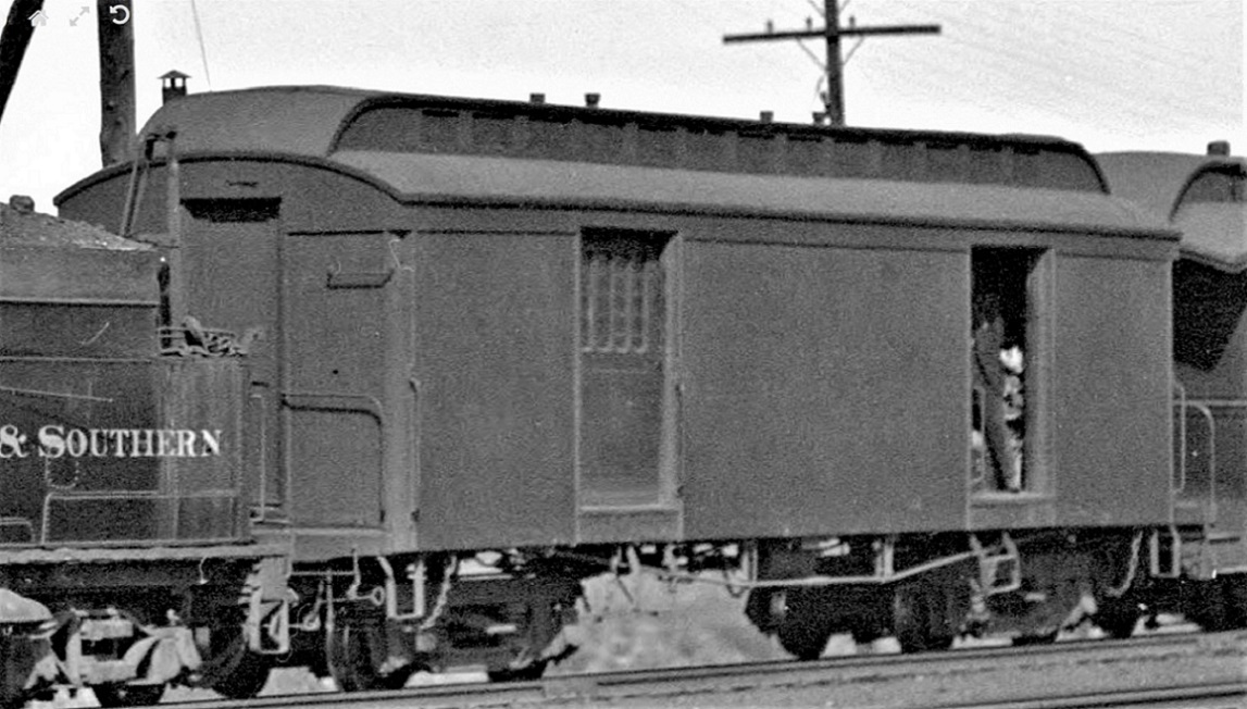 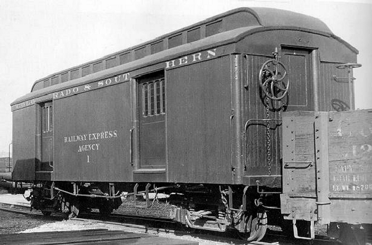 On the real deal, the lower roof panels arch downward on a constant curve, with the bottom of the roof panel sitting atop the car body wall. The edge of the multiple layers of the roof panel build up are exposed and trimmed to be smooth. The exposed edge of the roof panel overlaps the letter board by about an inch. Mr. Micrometer and I studied the photos in enlargement. We estimate that the thickness of the exposed edge of the roof panel to be about 2", given that the letter board is 6" wide. So the solution to the roof issues is very simple (so simple, that it worries me that I'm overlooking something critical): I'm going to finish building up Bill's roof as designed. When all the pieces are installed and the glue dried, I will again gently sand the bottom of the assembly to insure everything is flat and in one plane. As a last step, I will glue S scale 2x2 strip wood (0.030"x0.030") to the bottom edge of the roof, the length of the roof on each side. The bottom edge of the 2x2 will be flush with the bottom of the roof. I temporarily taped the roof to the body and taped the 2x2 in place: 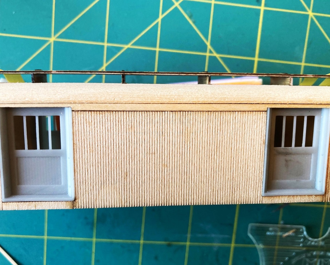 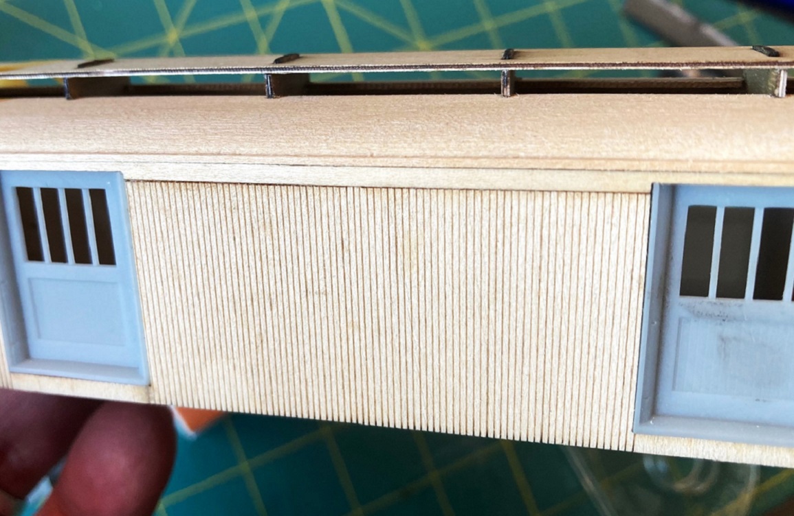 The 2x2 strip accomplishes two things: 1. It corrects the roof width problem--by adding 0.030" of strip to each side of the roof, the roof now overhangs the letterboard by 0.015", about an S scale inch. 2. It creates the illusion of the exposed roof panel edge. I like Keith's idea of reshaping the lower roof contour, sanding down the tight radius curve near the edge of the roof to a more constant contour. But I don't think it possible with Bill's design. The lower roof panels are only 1/32" or 0.030" thick. The bottom of the roof panels have many parallel, laser engraved "bend" lines to allow the roof to bend over the profile ribs for gluing and clamping. These laser cut lines are deeper than they look. The intact portion of smooth wood on the top side of the roof panel is likely about as thick as a piece of printer paper. I'm afraid to try to sand down that rounded ridge, lest I quickly end up in the laser bend lines and cause the roof panel to begin to split. (I now understand why the masking tape was applied before gluing and shaping the lower roof panels, as above). Anyways, that the new plan. If I've overlooked something obvious, and screw up the roof, I can always follow Chris Walker's suggestion: . . . just smash it and start again. 
Jim Courtney
Poulsbo, WA |
Re: Leadville Designs Baggage/Express 1 in C&Sn3
|
Administrator
|
Hi, Jim. I've remained on the sideline through this discussion awaiting the solution to become apparent as I was sure it would. Keith said it as well as I could have with the following:
"I appreciate Bill's efforts to develop the kit and do most of the hard work for us. Errors like this happen and I find these sorts of problems drive my ingenuity and make me a better modeler." I have had to deal with situations like this more times than I can remember, often wondering if the best thing would be to just discard everything and either forget it or keep working to find the way to resolve the problem. Each time, I've found a way to solve the problem. I could cite several examples such as the cab for #537, but the best example in this case was actually noodling how to build the roof on Baggage and Mail #13. To build #13, I used styrene parts and identical Evergreen material to create the body from an old Crossing Gate Styrene D&RGW coach kit using Ken Martin's drawing to guide me. The body came together pretty well, but I was worried about the roof. The #13 would be shorter than the coach was so I had to decide whether to try to modify the Crossing Gate three part roof or to try to create one on my own. In the end, I decided to try to use the Crossing Gate material, since I had them, and try to shorten the sections to get the length right. The other issue was to have to get the ends right, as there are no platforms. Somewhere I read that the #13 had to undergo a roof repair in the late 20's because of a pretty bad sag. So what I did was cut the roof at the same point where the wall separating the Postal end from the Baggage end was and carefully sanded the three parts square and straight.to further conceal the joint, I applied a piece of 3M Magic tape, and after painting, the joint is virtually invisible. And if anyone was to notice, I had a built in excuse as a scar from the latest roof repair. I used included Grand Clerestory windows, which I was told once were acually made to fit old wood body coach kits made by Star. They may not be perfect, but hey, comprimises are part of the game, right? So, in the end, I completely agree with Keith's philosophy about overcoming obstacles along the way as that makes us better modelers. You, Jim, are an excellent modeler, and I had no doubt you would find your way through this. I'm sure you will be successful. I'm feeling a lot better these days and am looking forward to building up the new trucks for #13. I've spent a lot of time trying to figure out how to get those proper trucks for it. Thank God I've lived to be able to get my paws on them at last! Thanks Bill! |
Re: Leadville Designs Baggage/Express 1 in C&Sn3
|
|
Thanks, Mike, for the kind words.
Philosophically, I agree with you and Keith completely. Every new C&S model project presents new challenges and problems to solve, which often make future projects easier to build. If I can figure out how to complete the roof of baggage number 1 to my satisfaction, the solutions will be useful when building Bill's other passenger car kits in the queue: the Pullman sleeper, the Pullman coaches, C&S coach 63, etc. I am in no way denigrating Bill Meredith's clever kit. The car body is building up nicely, the roof is tedious, but coming along. No kit is perfect. I don't expect them to be. About 15 years ago I came to accept that any C&S model "kit" was merely a box of custom parts to be used to essentially scratch build a C&S model. I haven't built up a "kit" from just the parts in the box since. If I have better, crisper detail parts, I substitute them, or fabricate them to be more accurate. If a kit part seems overscale, I will build a replacement part, some times using other materials. Mike's beautiful C&S number 7 locomotive project has taught me that even brass models can be modified with materials such as styrene and wood--what ever makes the model look right! There is a certain freedom in no longer being a brass purist, especially given my soldering skills . . . My self imposed pause on this project ended last night. I'll be back to work on the roof this weekend. I'll post more progress as it occurs.
Jim Courtney
Poulsbo, WA |
Re: Leadville Designs Baggage/Express 1 in C&Sn3
|
|
OK, back to building the roof.
The first order of business was the resin printed clerestory end pieces, testing them to see how they fit --- they don't. The bottom of each print is supposed to be flat. They are, but I lightly sanded off some printing imperfections. The back side of each print (the gluing surface) is supposed to be flat. They are, but are not square relative to the floor. I fixed this with my True Sander, checking with a machinist's square. I also checked the ends of the wood build-up. They were square in the vertical, but my imperfect assembly produced a bit of skew from one side to the other. Again, I fixed this with the True Sander. The critical issue is the curvature of the underside of the prints. The very end of each print has a curvature that matches the end wall curvature almost exactly, but for only about 1/64th inch depth. Then, moving toward the back of the print, the curvature narrows and the bottom becomes thicker and irregular. The end wall build-up is 0.080" thick and won't clear the bottom of the print, at that point, to let it sit on the car body end as it should. Having pondered this, I decided that I needed a hard cylinder to wrap with sand paper and sand down the bottom of each print. I spent an hour or so interviewing every wine and liquor bottle in the house as to their radius of curvature. I finally found a bottle that seem to match (a craft whiskey, distilled on nearby Bainbridge Island). I wrapped it in 320 grit sand paper, taped tightly in the back. Then, holding the print by the clerestory portion between thumb and forefinger, and keeping the roof axis in line with the axis of the bottle, I stroked the bottom of the print downward against the sandpaper: 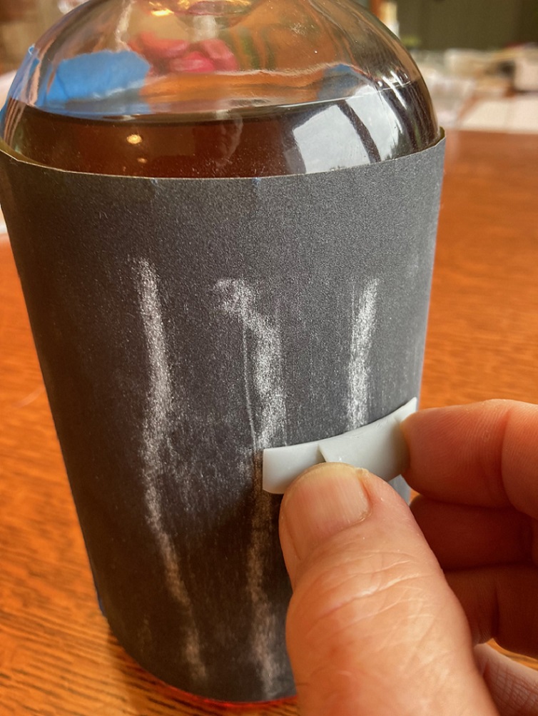 I repeated this motion many, many, many times! In medical jargon TNTC (too numerous to count). I was careful to not let the bottom of the sides or the very end of the print touch the sand paper. The idea was to begin removing material from the center of the part bottom. With repetition, the shape of the bottle begins to create a new, uniform curvature to the bottom. And with more repetition, the new curved bottom eventually approaches the end and sides of the print. Left, just started, right, almost done: 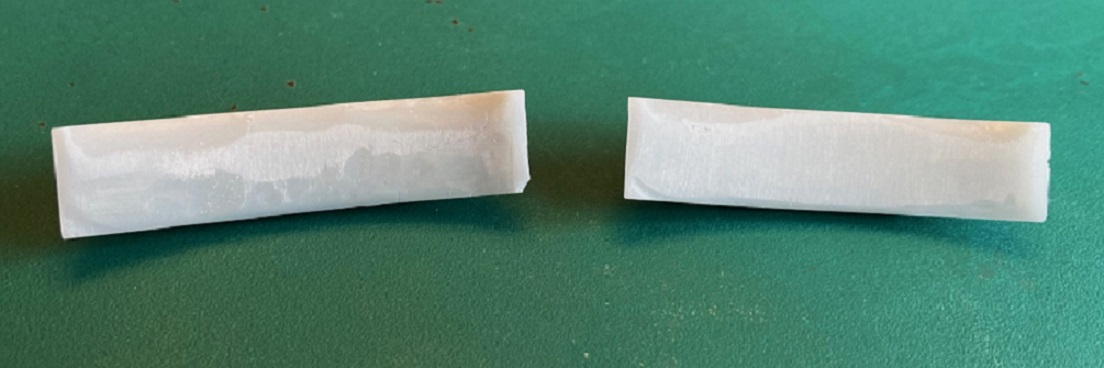 ProTip: Sipping some of the contents of the whisky bottle seemed to make the repetitive process go smoother, if not faster. With periodic testing of fit, when I was satisfied that further sanding would not improve the fit, I moved on to finishing the wood portion of the roof. The clerestory sides have slightly down turning, pointy ends. The instructions say that you may need to slightly sand these ends so that they will fit into the recesses of the printed ends ---- you will. Rather than try this after the sides were attached to the wood clerestory, I assigned A and B ends to the roof build-up, the printed ends and the clerestory side pieces. I sanded the ends of the clerestory sides until I could insert them into the printed ends with the engraved vertical line even with the back of the print. Then the clerestory sides were glued to the side of the roof framing, again using the engraved lines to position them: 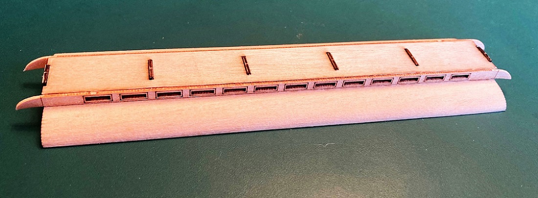 When the sides were dry, the joints were reinforced with thin ACC, applied with a piece of wire. Then on to the top roof panel. Liberal amounts of white glue was applied to the protruding tabs on the top of the roof framing, and a bead run down the top edge of the clerestory sides. While the glue was still wet, I visually centered the ends of the top panel insuring that roof overhang was equal, and tacked them in place with ACC. The top roof panel needs to curve slightly from the center down toward the edges. There is no way to clamp the panel, you must hold the edges down with your fingers for what seems an eternity. The holes are for the lamp vents. 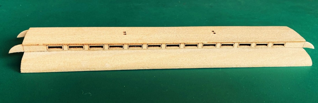 Finally, now to attach the printed ends. The instructions say that it is important that the bottom of the printed ends is flush with the bottom of the wooden roof. But . . . the clerestory side ends, will only fit in their printed recesses if the bottom of the print is about 0.020" higher. Figuring that I could add styrene strip filler to the bottom of the print later, and sand everything flush, I chose a nice tight fitting joint. I put little dabs of Gorilla ACC gel on various places on the back side of the first print, lined things up in all dimensions and firmly pressed the print against the wood assembly until the gel hardened. I reinforced the joint by applying thin ACC along all visible seams, top and bottom. When everything was dry, I repeated the process for the other end. Some final clean up was required: I added 0.020x0.030" styrene to the bottom of the extreme edge of each roof end with ACC. When dry the entire roof assembly was sanded flush. Turns out that the wooden top roof panel is wider than the printed top roof panel on the ends. I used a sanding block to sand the sides of the top roof panel, until everything matched. The printed top roof panel is also a bit taller than the wooden roof panel, so that too was sanded down. Here's the roof at this stage: 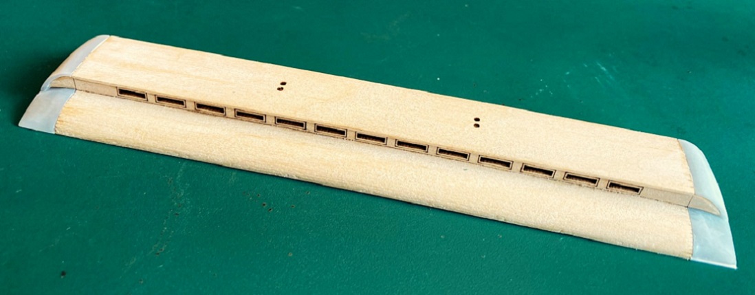 I still need to add the 2x2 strips to the sides to correct the width issue, but felt that I should wait until I have puttied all seams and sanded everything smooth. I may even prime the roof at that point, correct any divots that were overlooked, then re-prime before attaching the side strips. Anyways, here's how the roof looks atop the body:  And my "whiskey bottle sanding" seems to have produced a joint with the end fascia that looks pretty good: 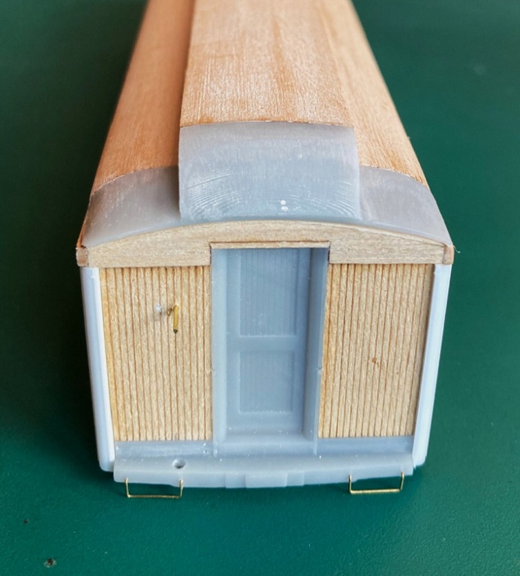 For mental health reasons, I'm going to put the roof aside for a while, and get back to the car body. Next up, bolsters, truck mounting and couplers . . .
Jim Courtney
Poulsbo, WA |
«
Return to C&Sng Discussion Forum
|
1 view|%1 views
| Free forum by Nabble | Edit this page |