Leadville Designs Baggage/Express 1 in C&Sn3

123

123
Re: Leadville Designs Baggage/Express 1 in C&Sn3

|
Time for the Sunday Eve progress report. The past week was pretty busy, little time for model building. But the little guys from Denver put in a lot of overtime, so there is some progress to report.
First off, since the wood working part of the kit is about done, I gave the body and the roof, inside and out, several liberal coats of Testor's Dullcote from the rattle can. This is an idea borrowed from both Bob Stears and Geoff Hamway. The Dullcote seals the wood, so any future application of liquids (water, acrylic paints, alcohol, decal solvent, even thin ACC) don't raise the rain of the wood and cause distortions or unsightly visible grain. I believe that Geoff actually paints his wood car bodies, prior to adding details. I chose the Dullcote, as it is transparent, allows me to see the engraved locator markings on the car underside. Couplers and bolsters. You should decide which couplers you are going to use and how you will mount them. Bill makes no provision for coupler mounting in the kit, other than leaving an empty space. I have chosen to use Kadee short shank, standard knuckle "whisker" couplers. I have been using the "Darwin" gear boxes manufactured by The Coach Yard on all my passenger cars. These gearboxes are the thinnest available, so the couplers don't droop, and have a very small mounting hole (a 1.2 mm screw will fit). From the RPO/coach build up, I determined that if the car is riding the correct height above the rail, the Darwin gearboxes need a 0.060" thick mounting pad, glued to the bottom of the floor, to have the coupler at the right height. As the end beams have at wider bottom part, I laminated 0.020" and 0.040 inch styrene cut to the width of the gear box, leaving a notch to allow the gear box to be mounted for close coupling (the inside face of the knuckle is only 4 scale inches from the end beam): 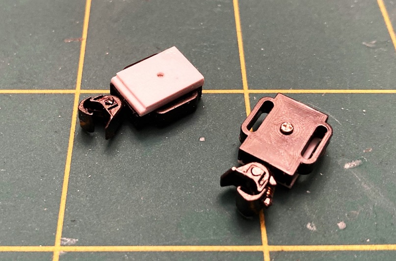 I positioned the couplers and gear boxes while screwed to the pads, then glued the pads to the car bottom / end beam with MEK, reinforced with thin ACC: 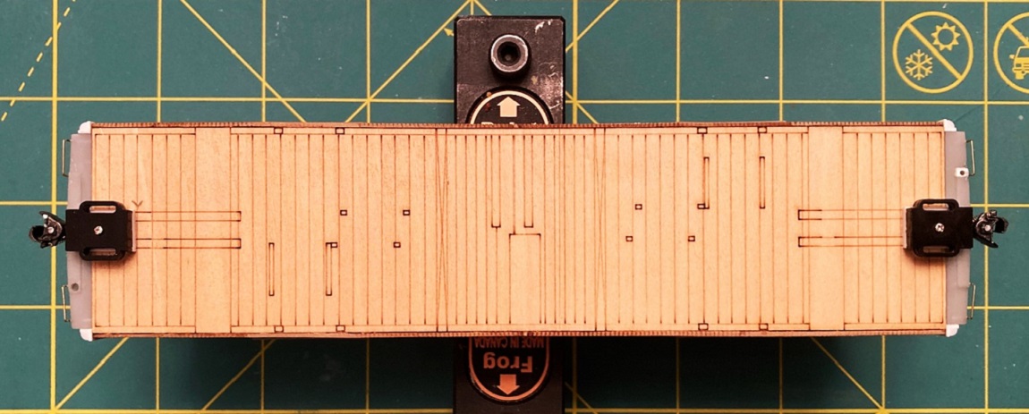 Bill's bolsters consist of two cut sills (extensions of the center sills, below the floor sheathing) and a square of plywood for the bolster face. Over this assembly, two etched nickel-silver overlays are folded and glued to the center assembly and the car floor at the edges. As bending metal shapes consistently is not one of my strong suits, I chose to build up the bolsters of styrene, as I did on the RPO/coach, using my own design that will match car height and coupler height to my Overland brass coaches. The bottom face of the bolster, that rests on the truck bolster, should be about 10 scale inches (~0.160") below the bottom of the floor in S scale: 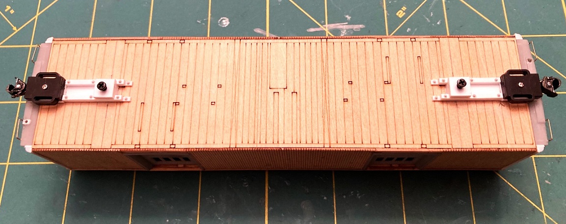 The bolter pads were drilled and tapped for 2.0 mm screws. When all the styrene build up was dry, I reinforced the attachments with thin ACC. Then, the lateral bolster plates were added along with the truss rod anchor straps. Small brass eye rings were installed at the inside edges of the bolster, to provide a gluing surface for future truss rod installation: 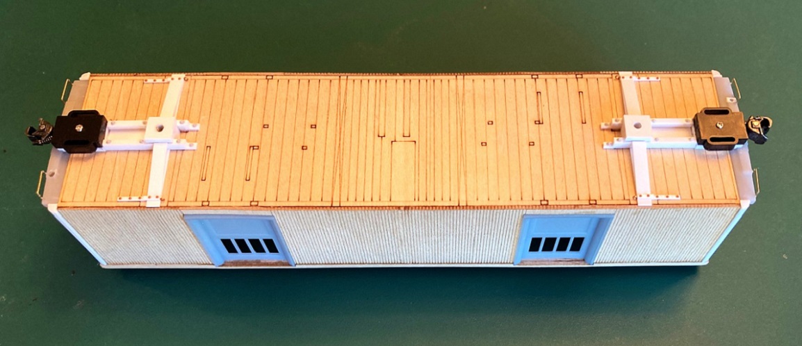 I haven't yet assembled the 5'-6" Commonwealth trucks that are appropriate for this car in the 1920s, so I temporarily mounted some modified PBL 5'-0" composite trucks. Note that the Folio sheets for baggage number 1, updated to 1918, show the little car riding on the shorter wheel base composite trucks--best I can tell the Commonwealth trucks came along about 1920. Beginning to look like a baggage car: 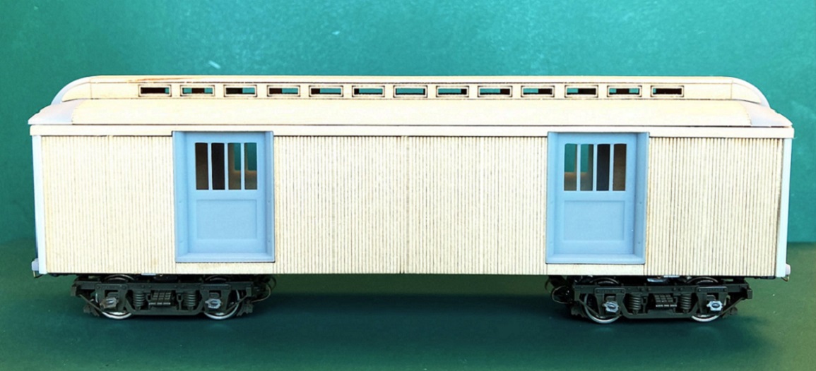 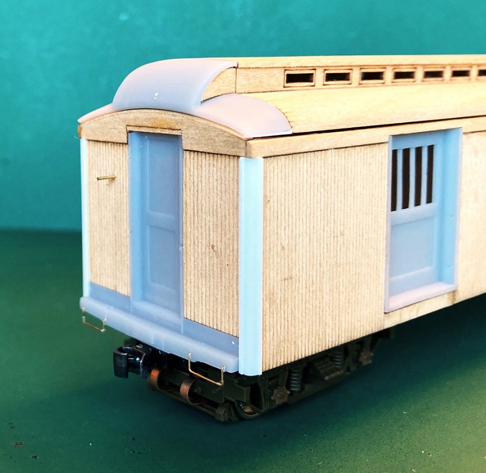 And when coupled to the RPO/Coach 43, car body height and coupler height seem just about right:  I really, really need to work on that roof. Before any further details are added to the underframe of the car body, it's time for the last major ham-handed chore: Drilling all the grab iron holes . . . 
Jim Courtney
Poulsbo, WA |
Re: Leadville Designs Baggage/Express 1 in C&Sn3
|
|
Jim,
The car is looking great! With putty (I assume that's your plan) the roof will come out great. One question: Do you fine sand between the liberal Dullcoat layers? Thanks!
Dave Eggleston
Seattle, WA |
Re: Leadville Designs Baggage/Express 1 in C&Sn3
|
|
This post was updated on .
Hey Dave, thanks for the encouragement.
As to sanding the Dullcote between applications, I could've, maybe should've, but chose not to. In addition to sealing the wood, the layers of Dullcote, when dry, create a new surface on the wood that allows me to use MEK (sparingly) to attach styrene parts, like NBW for grab irons and the styrene build up of the bolsters, above. I figure that when everything's done, I can prime the model and then sand any imperfections prior to the green color coat. As to the roof, Geoff Hamway has been providing moral support by email. Geoff recommended that I not fill the roof seams with the standard model building putty (Tamiya, Squadron, etc.) as he has had those products crack over time. He recommended that I try Milliput, instead. Milliput is a UK product, popular with military figure modelers. It is a two-part epoxy putty. Not knowing anything about the stuff, I've watched some YouTube videos. I've learned that the stuff, after thoroughly mixed, can actually be thinned with isopropyl alcohol to a creamy consistency and applied with a small brush: https://www.youtube.com/watch?v=EY8Acdi59M0&ab_channel=MarcoFrisoniNJM As I need to try to fill all the little alligator clip bite marks on the roof, I thought it best to have an un-sanded layer of Dullcote to which to apply the thinned Milliput, so the alcohol doesn't get into the wood grain. I may be overthinking this. Anyways, I see lots of sanding of the roof in the future, after the seams are filled, before priming.
Jim Courtney
Poulsbo, WA |
Re: Leadville Designs Baggage/Express 1 in C&Sn3
|
|
Looking good, Jim!
Thanks for diving in on this build. I am excited to learn about the Milliput.
Keith Hayes
Leadville in Sn3 |
Re: Leadville Designs Baggage/Express 1 in C&Sn3
|
|
This post was updated on .
Well, it's been an couple of weeks since I posted progress on this project. Very busy taking my wife to doctor's appointments for her many health issues. And the contract with the little people from Denver expired, they flew home last week for Thanksgiving with their families. Nonetheless, an hour here and an hour there and there is some progress to report.
Roof: Milliputian Adventures: I set out to fill all those seams in the roof with Milliput, as Geoff Hamway had suggested. The manufacturer's info on the stuff is here: https://www.milliput.com/howto.html The YouTube video on thinning the stuff and applying with a brush is here: https://www.youtube.com/watch?v=iWT9mnaUy0M&ab_channel=ScaleWarMachines I followed the video exactly, mixed up a walnut sized piece of Milliput, squished it down on a jar lid and formed a tiny volcano. I then added a few drops of isopropyl alcohol to the mouth of the volcano and kept some nearby. I used a 00 brush to mix the alcohol and Milliput to various consistencies, from soft butter, to sour cream to skim milk (to use a dairy metaphor). I used the buttery stuff to brush it into the seams between the printed roof ends and the wood roof proper. I sat the roof aside--the manufacture says the stuff hardens in about 3 hours, fully cured in about 6 hours. Being an impatient lad, I watched the clock and at 6 hours began sanding the seams smooth. I was dismayed that tiny flecks of Milliput was pulled up with my sanding sticks. Perhaps thinning the stuff delays the curing time? For all future applications of thinned Milliput, I let it cure overnight before trying to work it. Before the 2nd application, I noticed that both end resin prints had a corner that wasn't really square, slightly rounded, a printing artifact. So I cut thin strips of 0.005" styrene and glued them onto the underside of the roof end, keeping the outside edge of the strips exactly in line with the outside edge of the wood roof portion. These would be forms to build up Milliput at the corners (they were later sanded off flush with the roof bottom). I also filled the four holes for the lamp vents on the top roof panel with un-thinned Milliput. Bill got these holes too close together, 6 scale inches on center. They should be 12 scale inches apart on center, per Ken Martin's plans. Anyways, this is how the roof looked after the 2nd Milliput application had dried and been sanded a bit: 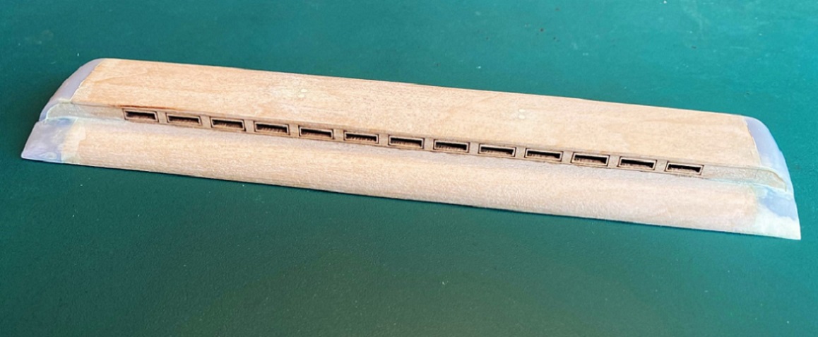 I realized that the dried Milliput was about the same color as the raw basswood and I really couldn't see what I was doing. So I gave the entire roof a thin coat of Tamiya fine grey primer: 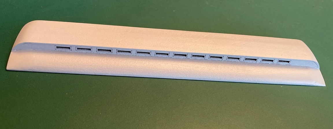 Wow, this hybrid roof design of Bill's might actually work! Note that there are very fine gaps in places where the clerestory side panels was joined to the lower roof panel. These would need to be filled with thinned Milliput. And the right corner needs further build up. The ends of the clerestory side wall, in the printed ends needs more filling and filing as well. And the entire roof needs much, much sanding to get rid of the roof grain. Here's how the roof looks at this point, sitting atop the body: 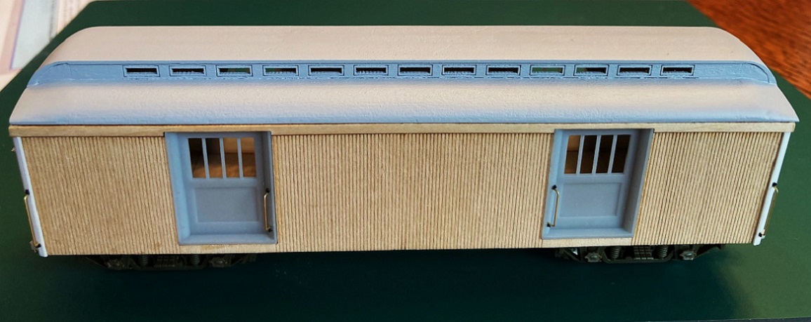 Before going on to the 3rd Milliput application, I decided to add the strips to the side of the entire length of the roof to correct the width problem. I had intended to use S scale 2" x 2" strip wood (0.030" x0.030") but ended up using HO scale Evergreen 2 x 3s (0.022" x 0.033") instead. The shallower roof overhang better matches my Overland brass coaches and Roy's printed RPO/coach 43. I placed the roof on a piece of window glass, weighted it, and applied the styrene strip to the edges with MEK. When dry, I reinforced the joint on the bottom with thin ACC. I decided that I wanted the end of the lower roof panels to have the same exposed edges as on the side. And despite my "whiskey bottle" sanding, there was a bit of a gap where the roof joined the body, that needed to be covered. It's pretty near impossible to gently curve 0.010" x 0.030" styrene strip or stripwood on edge (yep, I tried). So I resorted to using Plastruct 0.010" x 0.010" square rod, real cat whisker stuff:  A strip was carefully tacked to the center or the arch of the roof with a little MEK, then reinforced with a tiny bit of ACC on the bottom. When dry, the two ends of the strip were gently curved down and attached to the side strips, keeping the lower edge of the end strip flush with the bottom of the side strip, and glued with MEK. The lower end strip joint was then reinforced with ACC. After allowing a couple of hours for things to dry, it was a simple matter to apply two more strips to each end arch, adding them atop the previous strip. When the MEK was dry, the protruding ends were cut flush with the outside edges of the side strip. and the curved end strip very lightly sanded. It ended up looking like this: 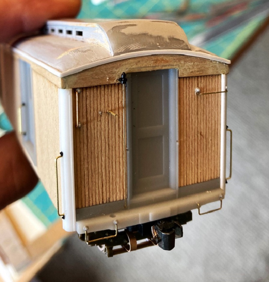 With the sides and the ends of the roof now framed, a 3rd application of Milliput was applied to the roof at the corners and at the edges of the clerestory sides. After more sanding and a second coat of primer, the roof now looks like this: 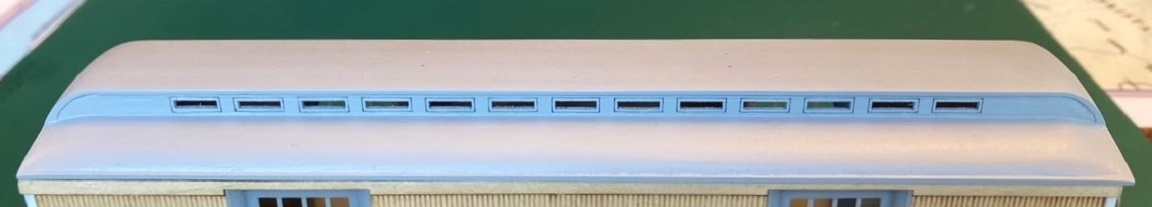 I still need a 4th Milliput application to finish building up the corners. Stay tuned . . . The Car Body Details: I successfully drilled all the grab iron holes, only broke one drill bit. Bill's resin doesn't mind being drilled as much. All the grab irons were formed of 0.015" wire: 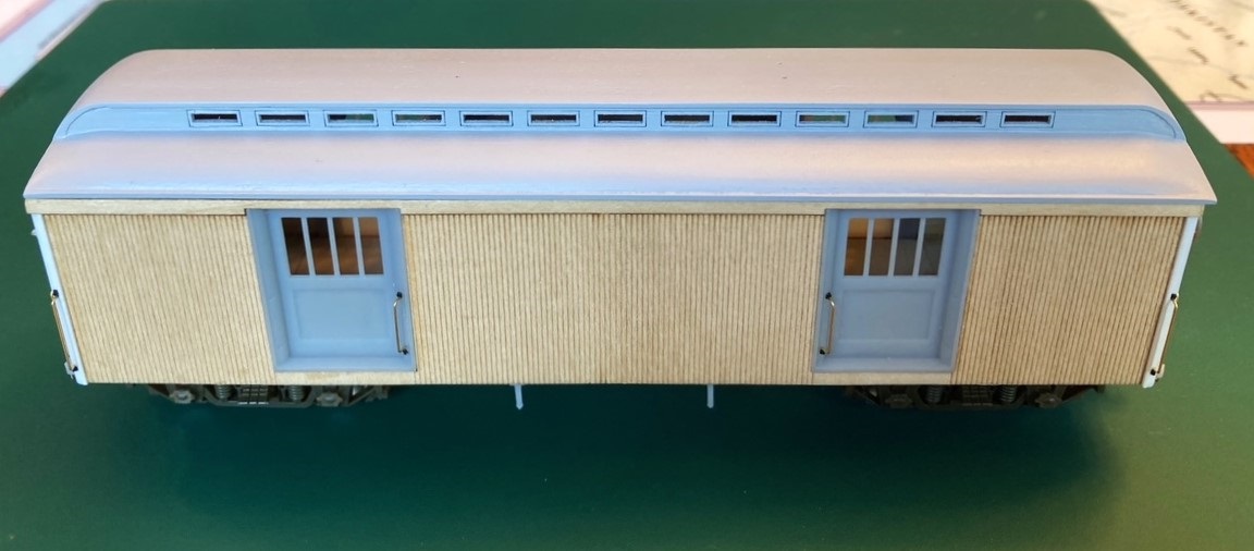 Bill printed two drilling dimples for 20" vertical grabs on each of the quarter round frames on either side of each baggage door. But C&S baggage 1, by the 1920s, had only a single vertical grab per door, located on the side framing closest to the center of the car:  Sister car, C&S Baggage 2, kept paired vertical grabs at each baggage door, all the way to abandonment: 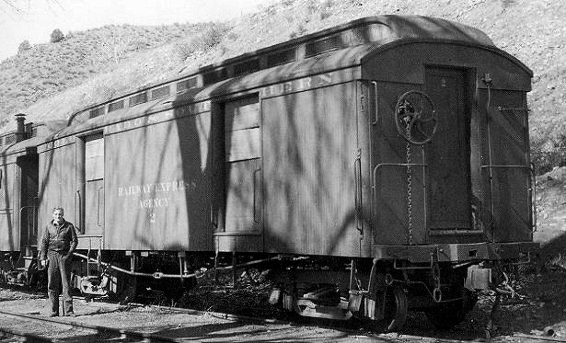 Estimating measurements from the photos, the end corner vertical grabs are about 30" tall. I used some old Simpson grab iron ends for the attachments instead of NBWs, as they more resembled the cast on tabs ion the photos. The ends were more challenging: 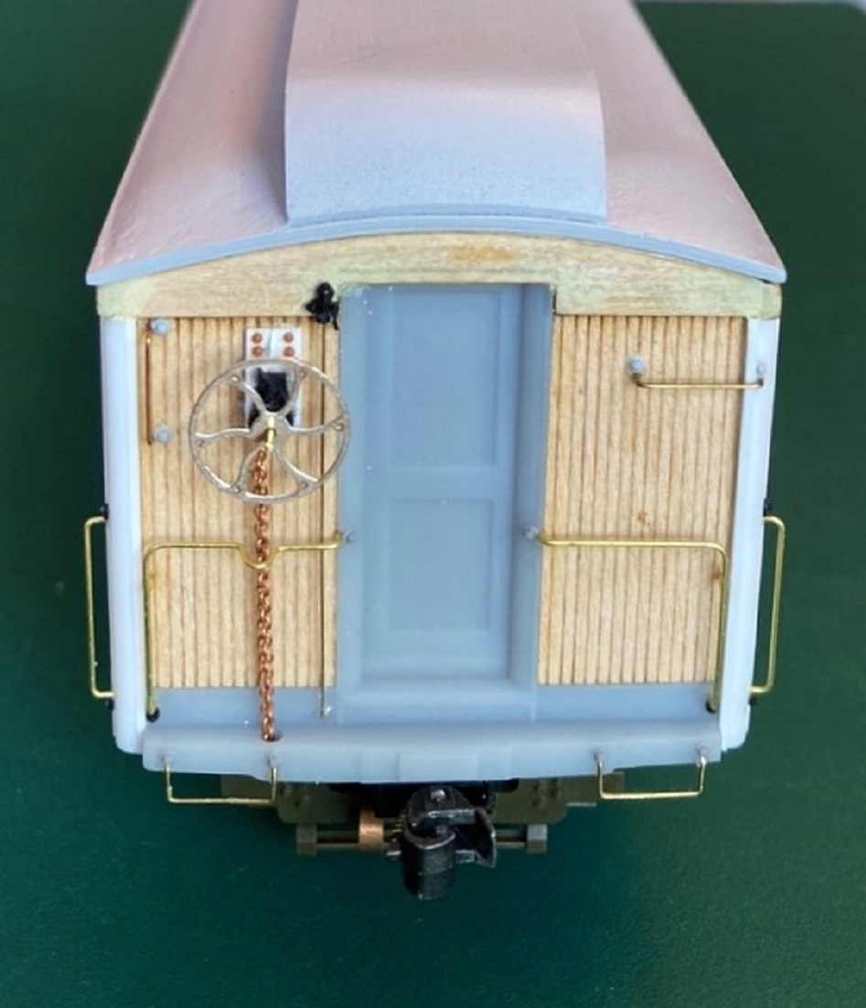 The straight grabs have NBWs (Grandt #101). The vertical grab at top left is 18", the horizontal grab at top right is 20". The inverted L-shaped end railings were formed from measurements to fit Bill's printed holes on the door castings. As I have several more baggage cars and Roy Steven's combine 20 to build, I went to the trouble of building a bending jig, so they will all be identical. Note the grab railing to the left of the end door has a loop-out to clear the brake chain. I attached the chain to the ends. Bill has printed a simple flat fixture to glue to the end wall for the big brake wheel mount. I chose to build up my own, trying to duplicate the ones on RPO 13, based on the photos that our departed friend, Doug Heitkamp, had posted on another thread, one of many gifts Doug gave us over the years: 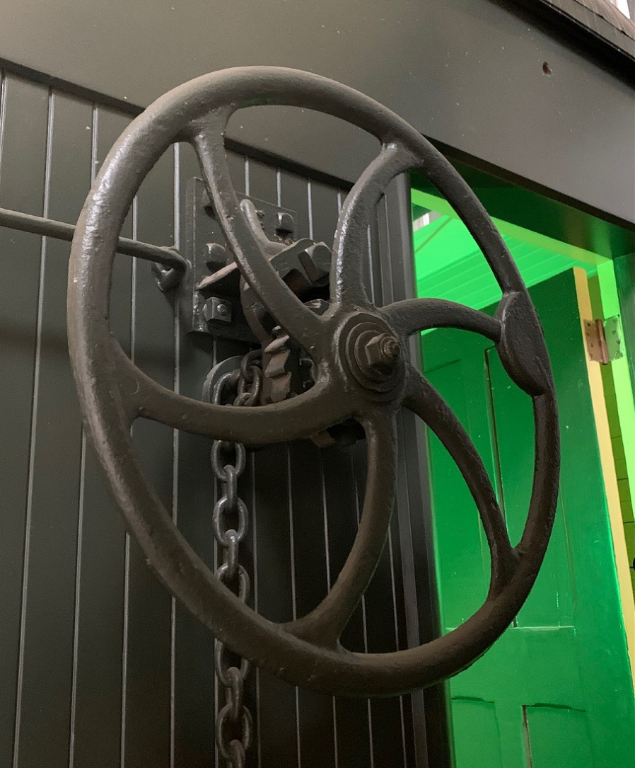 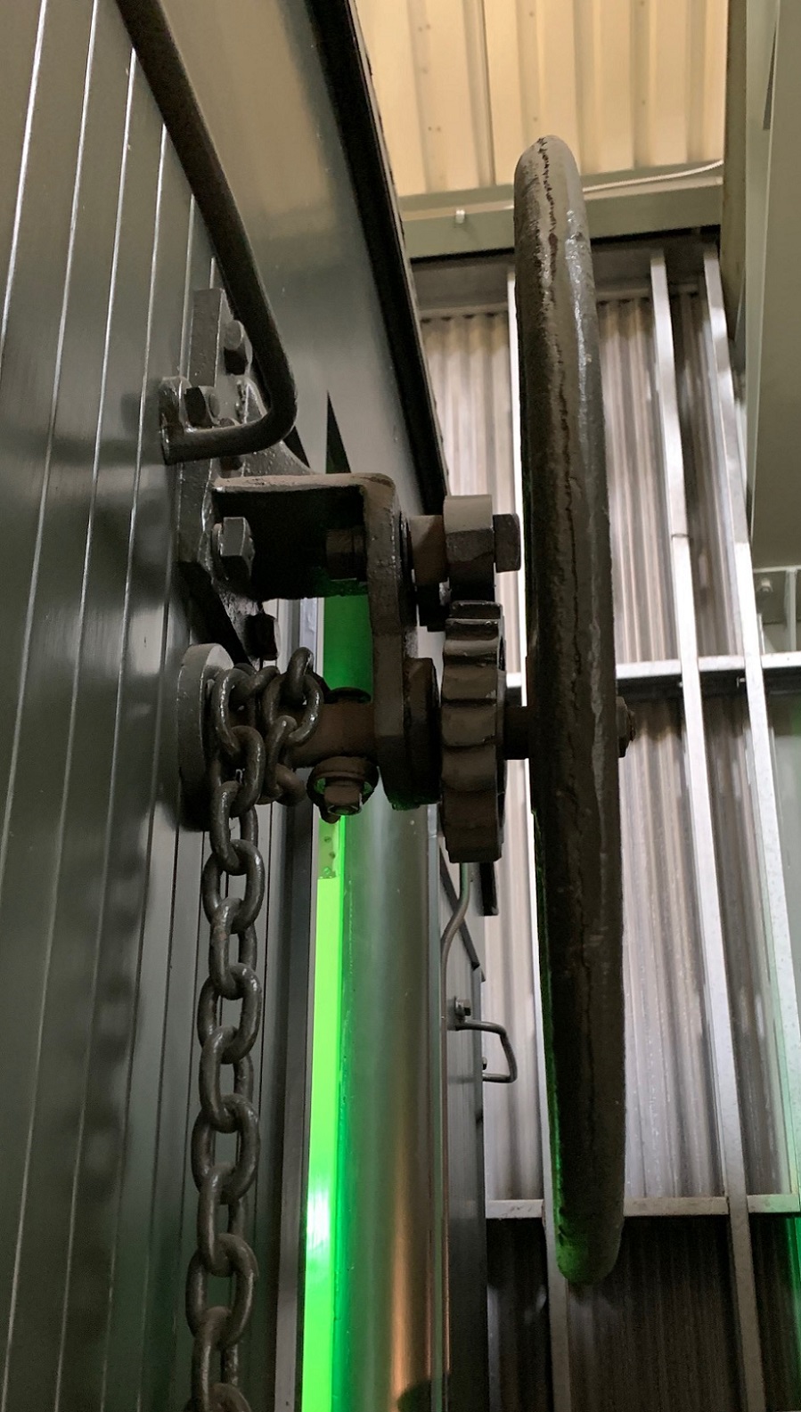 The big brake wheel etchings are temporarily placed for photos. They will be the last things glued on prior to painting. Next up will be turning the body over and starting the underframe detailing. You may have noticed that the needle beams are already in place.
Jim Courtney
Poulsbo, WA |
Re: Leadville Designs Baggage/Express 1 in C&Sn3
|
|
Terrific progress, Jim!
Thanks for your keen eye on those baggage door grabs. This seems to be true a cars 1 and 4, and possibly 10-12. I guess it is a reflection of a slower time when common sense dictated you look before you assume the grab iron is there? Thanks for sharing the Milliputlian techniques. The little people had a terrific time in Pulsbo. All they talk about is eating salmon and watching you sand the roof on a Bourbon bottle: they thought tat was a real hoot!
Keith Hayes
Leadville in Sn3 |
Re: Leadville Designs Baggage/Express 1 in C&Sn3
|
|
In reply to this post by Jim Courtney
Jim,
Your work in multiple materials and attention to detail is remarkable. You are on my hero list. The creativity and problem solving approach you bring to model building is an inspiration (bourbon bottle sanding tool) and pure genius. Thank you for sharing. I’m looking forward to seeing the completed model before it’s painted and after it’s painted. Again thanks. Lee Gustafson |
Re: Leadville Designs Baggage/Express 1 in C&Sn3
|
|
I’m looking forward to seeing the completed model before it’s painted and after it’s painted.
Me too!! Thanks for the words of encouragement.
Jim Courtney
Poulsbo, WA |
Re: Leadville Designs Baggage/Express 1 in C&Sn3
|
|
In reply to this post by Keith Hayes
Hey Keith,
I enjoyed having the little folks visit--they are hard workers! I offered them a new contract to come back and finish the baggage car with me, but they would never commit. I guess if you're only 1.5 inches tall, the sound of coyotes howling in the nearby woods all night can be unnerving.  It looks to me that baggage car 3 had only one grab for each baggage door as well:  And notice that the steps below the baggage door aren't centered on any of the cars, they are off-set to the side of the grab iron location. I guess if the same express car is used on the same passenger train, with the same crew, day after day, the crew come to reflexively know where to reach for the grab iron.
Jim Courtney
Poulsbo, WA |
Re: Leadville Designs Baggage/Express 1 in C&Sn3
|
|
I trust all had a good Thanksgiving! But frankly, all the shopping, food preparation, entertaining guests, clean-up and the persisting drowsiness of eating leftover turkey has greatly interrupted this project. But I caught up some this week.
Underside Detailing: C&S passenger cars, by their nature, rode very high above the rail, making all that brake rigging and stuff very visible. I really, really like Bill's detailing parts for the underframe, both printed resin parts and brass etchings. These are standard Bill Meredith parts, supplied with all his passenger car kits. My described buildup applies to all C&S passenger cars, with minor variations in placement. Having used Bill's parts to build out Roy's RPO/Coach, I learned after the fact that the underside detailing goes better by applying the parts in "layers", the parts directly contacting the floor first, followed by layers of parts as one build downward (or is it up??)  The first layer of parts are the mounting straps for the reservoir, cylinder and the truck brake lever fulcrums. These are supplied as brass etchings in the kit. I chose to substitute 0.010" Evergreen styrene strips, widths to match the etched parts, cut to length per the etched ones. With the floor coated with Dullcote, I could use MEK to attach the parts, and move them a bit 'til all was square and straight. Tichy 0.020 and 0.025 rivets were used for detail. The engraved lines for the reservoir mounting straps are too close together--use the reservoir print to locate them. Next the needle beams, with the tall, braced queen posts--the needle beam itself is trussed, there are two tiny queen posts printed in the mid portion of the needle beam. The truss rod is formed of 0.015" wire and glued to these little guys, and into the crotch of the main queen post brace. Since I will use this part for 7-8 other passenger car projects, I went to the trouble of making a bending jig. The bottom of the needle beam is 0.040" above the top of the truss rod (see below). I have no idea whether the trainline air piping is accurate for baggage car C&S 1. I merely copied the arrangement as on my Overland brass coaches. The "piping" is Evergreen 0.025" rod, with Grandt O scale plumbing fixtures (elbows, tees, unions and such). 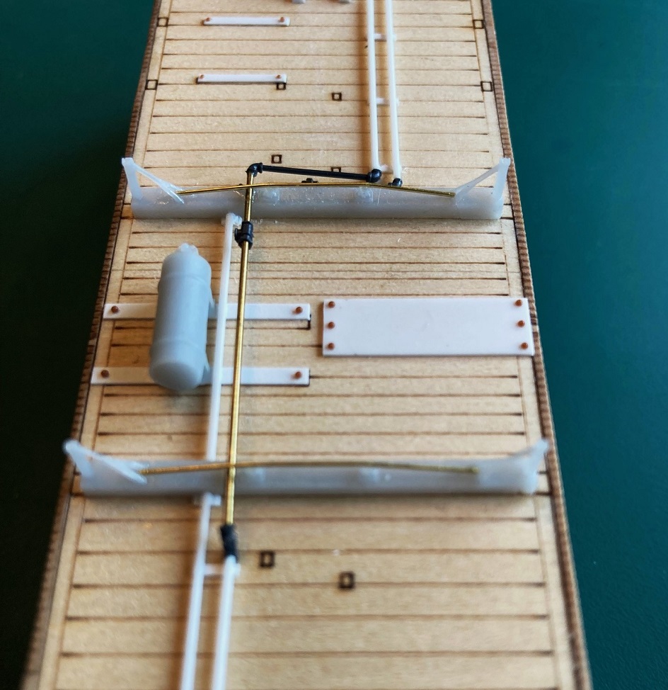 The reservoir's triple-valve was drilled 0.015" for a future branch trainline, then glued to its mounting straps. The air signal line is the outer pipe, is modeled passing thru the needle beams. The air brake trainline is the inner piping, it angles down and is attached to the underside of the needle beams. Small lengths of 0.010 x0.030 styrene were cut to length as supports for the two pipes. Here's how the first layer of detailing looks at this point: 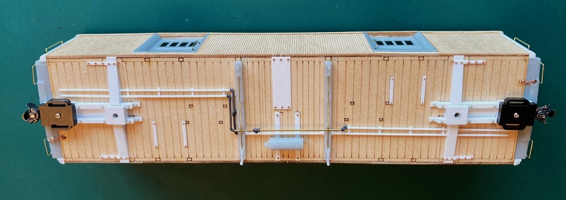 The second layer of detailing is the air brake cylinder, main brake levers, truck lever/fulcrums, connecting rods and clevises. The build up of the RPO/coach impressed me that the cylinder with its brake levers, tie rod and clevises should be built up first and installed as a subassembly. All clevises are PBL parts, to my eye, more in scale than Bill's etched clevises--your choice. All brake rods are 0.015" brass wire. Here is the brake cylinder assembly installed: 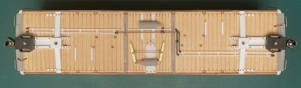 Note that there are three slightly different sizes of etched levers, these are the longest. The free end of the levers should end up at the center line of the car. Note that the branch trainline, with cutoff valve have been installed to the reservoir. Moving toward the bolsters, the fulcrums/levers for the truck brake lever must be built up from 4 parts: 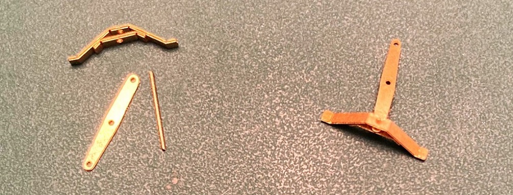 The fulcrum pieces have fold lines and a hole etched in the center. This can be confusing, as there are three pairs of such parts. The longest and shortest are for the fulcrums. The middle length ones are lower brake staff mounts for the end beams of coach platforms, not used in this model. I saved mine for use on Roy's combine 20/025. The larger piece is folded to shape, its little feet folded flat. The width of the fulcrum is determined by the distance between the two mounting straps. The shorter piece is then glued inside the fulcrum with the truck lever (the shortest of the the lever lengths) glued into the slot and all three pieces held together with a short length of wire. Here is how the assembled fulcrum/lever assembly looks glued to the mounting straps, the center hole of the lever at the car centerline:  Note that the brake rod with clevis has been added to stabilize the assembly. Also note that the clevis is inboard of the small hole at the end of the brake lever. We will see the importance of that location below. Next, the truck levers are connected to the main brake levers, with rods and clevises:  There are 6 etched strips with fold lines for the brake lever safety rails. I formed up two for the main brake levers, one would not fit between the cylinder support strip and the needle beam and had to have its little feet amputated. Before installing the two safety rails, the crossover pipe from reservoir triple valve and cylinder was installed ( length of 0.015" styrene rod). Here's how things look after installing all the air brake levers of the "second layer": 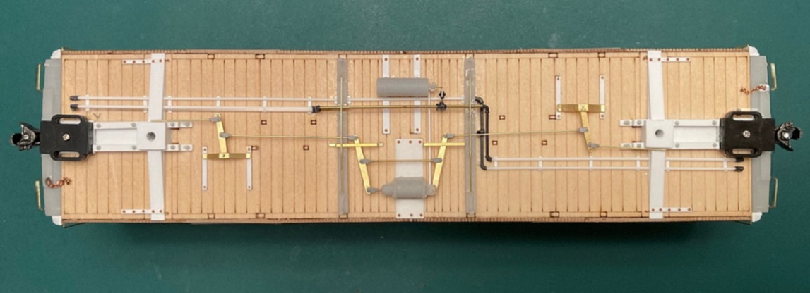 The "third layer" consists of the hand brake levers, rods and clevises. First, the remaining 4 safety rails were formed up and applied to the floor. Bill has engraved little foot prints for their locations. I was only then that I noticed that the two ends were not symmetric with these little marks. I carefully glued the rails in place, trying to keep them all the same distance from the side of the car body. When dry, the hand brake levers were carefully inserted beneath the safety rails and on top of the air brake truck lever rods. I positioned them so that they were parallel to the truck brake levers, then carefully glued them into place: 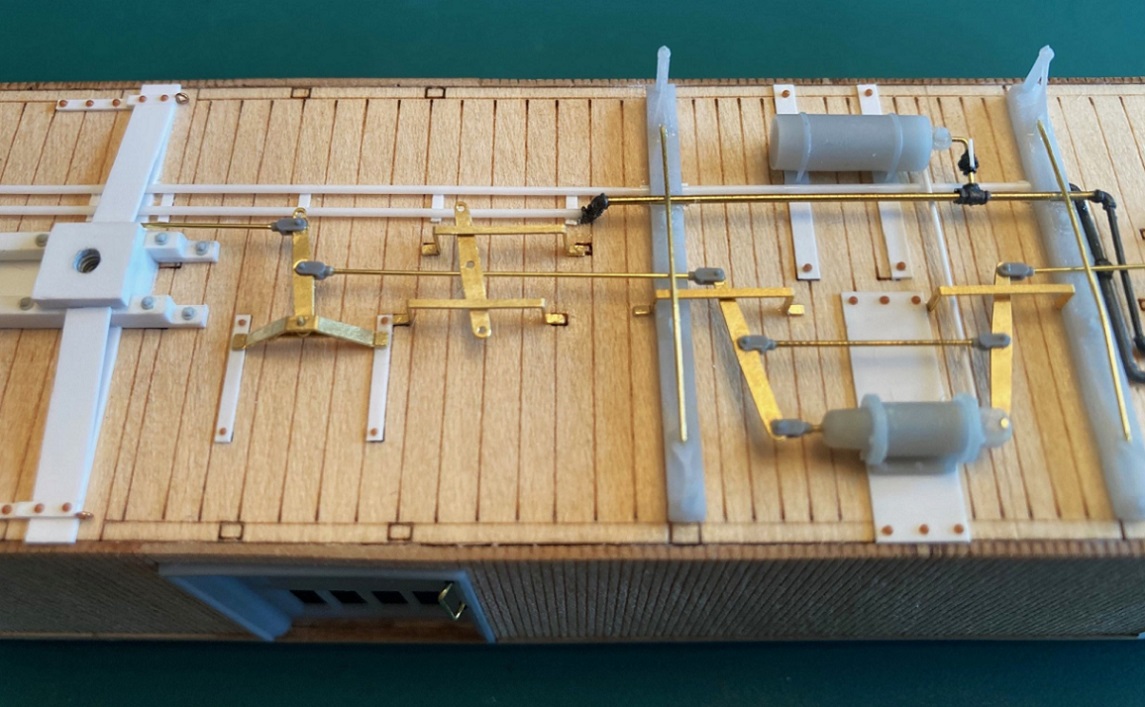 Next, the tie rod and clevises were installed between the two hand brake levers. Hand brake connecting rods with clevises were then attached to hand brake levers so that the rods passed through the bolsters and glued near the loops where the end brake chains were secured: 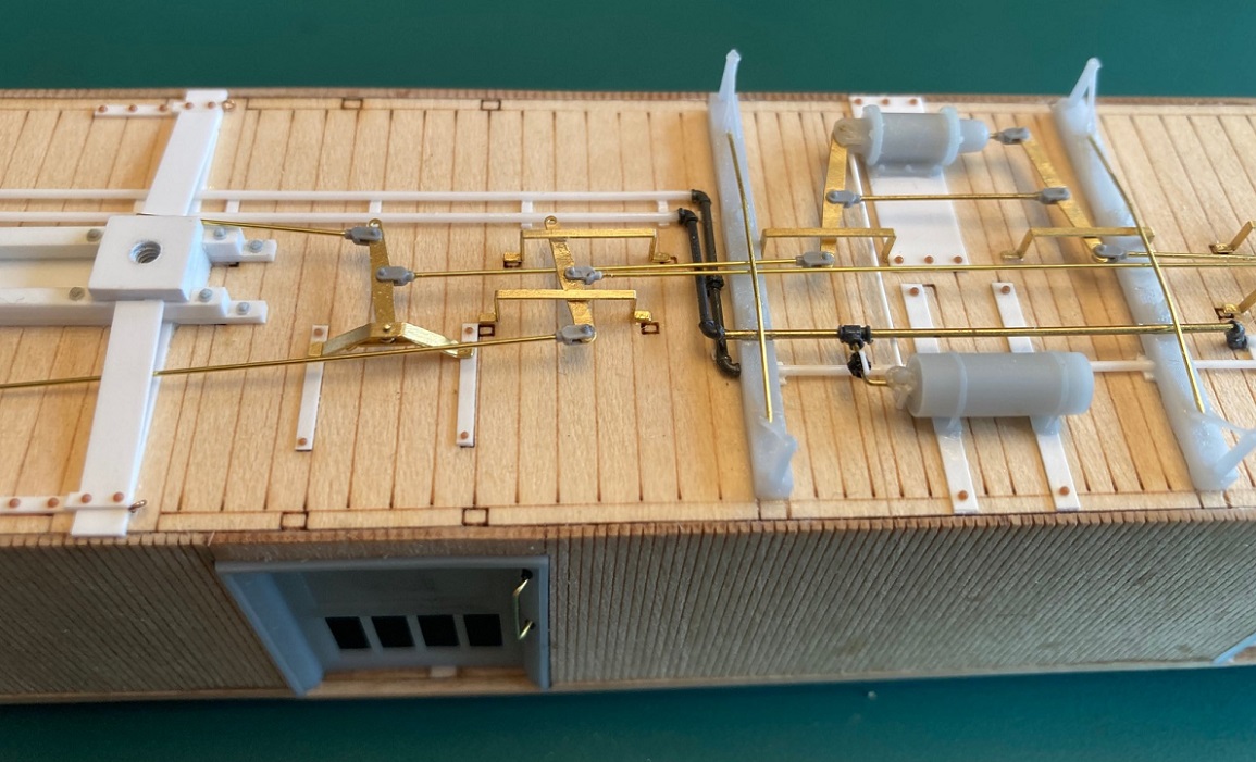 To complete this "third layer", the two brake lever systems have to be connected with lengths of chain between the the holes of the air brake lever and the hand brake lever. I measure the distance, added two links of chain for slack. On the RPO/Coach build, I actually tried to open the end links of chain to attach it to the holes of the levers. After two attempts I realized this was ridiculous--watch making not model building. Instead I used Grand #63 NBWs, cut from the sprue with long stems. I passed the stem first through the chain, then through the holes in the levers, and ACC 's them in place, trimming off the excess stem when dry: 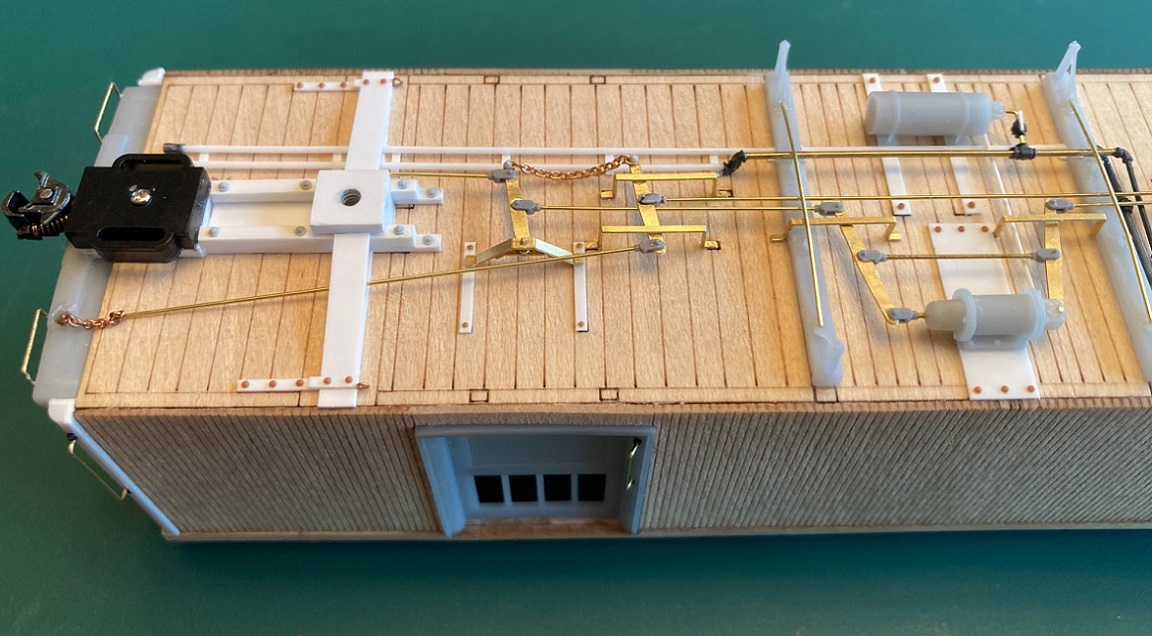 So here's how things look with the first three layers of details applied: 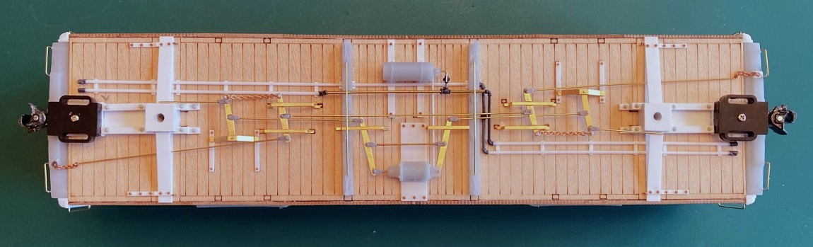 I'm hoping to finish up the roof tomorrow. This next week, I'll try to add the next layer of details to the underside: Truss rods, truss rod "keepers", baggage door steps and corner steps. And it's about time to put up the Christmas Tree . . .
Jim Courtney
Poulsbo, WA |
Re: Leadville Designs Baggage/Express 1 in C&Sn3
|
|
In reply to this post by Jim Courtney
Great stuff, Jim! Love seeing the progress...
|
Re: Leadville Designs Baggage/Express 1 in C&Sn3
|
|
This post was updated on .
Finishing the Roof:
I did a 4th application of thinned Milliput Sunday and finally built up the last pesky corner of the roof, so it looked like the rest. Also filled a few more small divots in the roof surface. When dry more sanding followed by a 4th light coat of Tamiya grey primer. This led to a bit more sanding of the corners, clerestory upper roof where it met the end, and smoothing of the clerestory sides at the pointy ends. After 4 applications of both Milliput and primer and much sanding, I felt that I had reached the point of diminishing returns. If I kept working on the roof to make it "perfect", I would likely screw up something that I couldn't fix. So, it was time to add the roof details. Bill has included nice little printed lamp vents for the top of the clerestory. But, in my parts box, I found several packages of Precision HOn3 lamp vents for D&RGW passenger cars. In S scale they match Ken Martin's plan almost exactly, and have a bit more detail in relief. So, I decided to use them for this project, rather than have them end up at my estate sale. One detail Bill completely overlooked was the smoke jack for the stove, located at the right corner of the "A" end of the car: 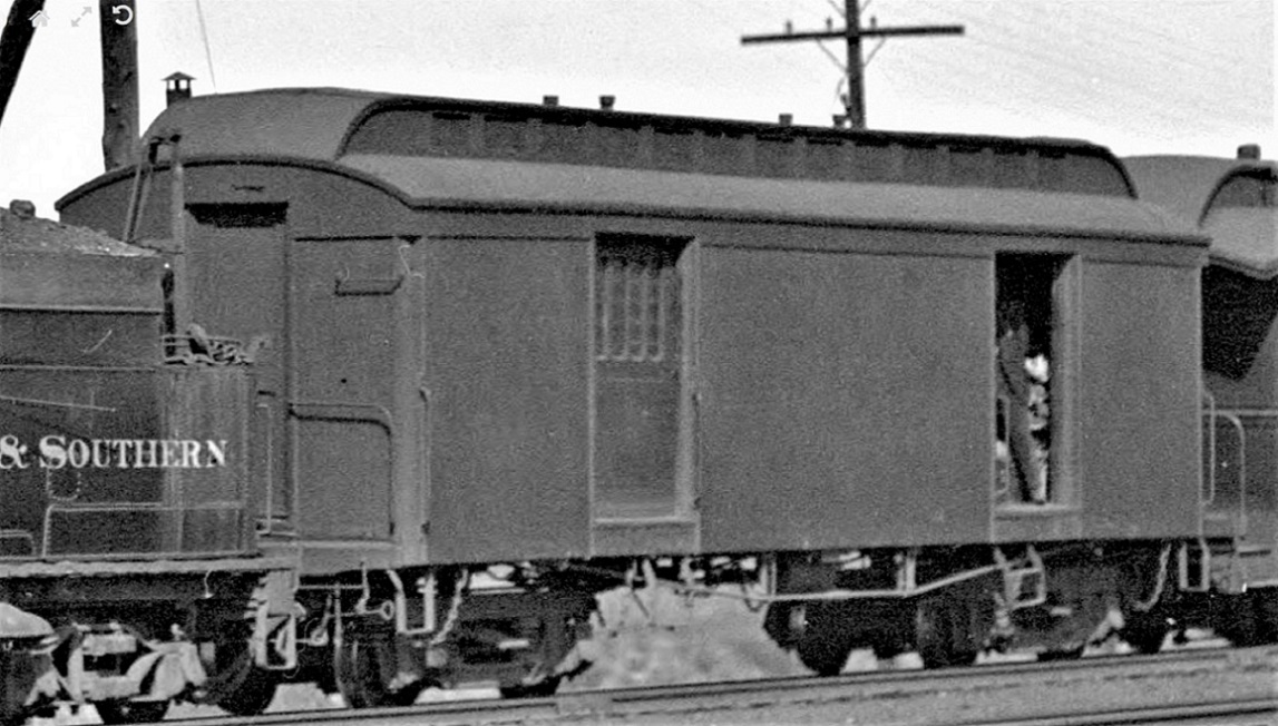 You can see it just peeking up to the right of the telegraph pole at the upper left corner. Again, in my parts box, I found a typical C&S style smoke jack, a white metal part, with the paired conical tops (see, there is a point to hanging onto stuff for 20-30 years). After building up some flashing of 0.005" styrene strips and attaching it to the clerestory, I laid out a mounting hole per Ken Martin's plans and glued it in place. After thoroughly dusting and blowing off the roof with compressed air, I applied a 5th (and hopefully final) coat of Tamiya primer: 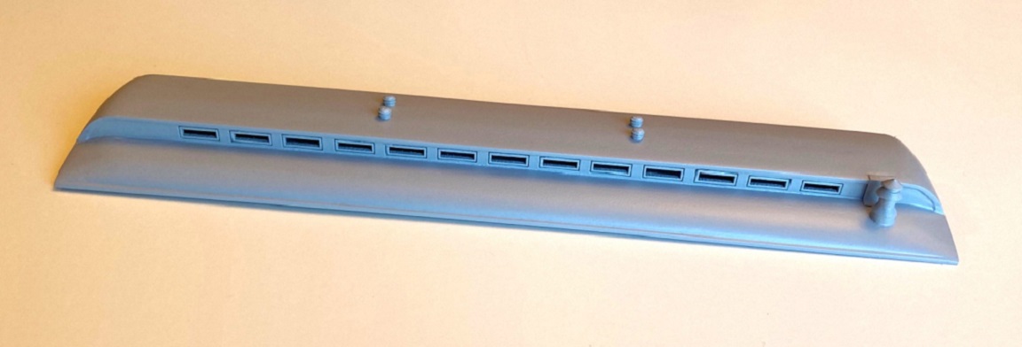 Here's how the roof looks atop the baggage car, awaiting a color coat after the car body catches up:  Although the assembly was a bit tedious, and I freaked out about some of the construction issues, I feel the finished roof turned out great, validating Bill's hybrid design. I've learned some new techniques along the way, don't know how I've been modeling all these years without Milliput. It occurred to me that the 4 layers of Milliput and primer followed by sanding was not to fill and finish the seams. Rather it was eliminating the irregularities in the grain of the wood portion of the roof. Geoff Hamway, always helpful, suggested a technique for this chore, that he had picked up from Jan Rons: Using "High Fill" auto primer, something like this stuff that I bought on Amazon: https://www.amazon.com/dp/B0088LVJU8?ref=ppx_yo2ov_dt_b_product_details&th=1 Evidently the stuff dries quickly, and can be sanded. Sorta like Bondo in a rattle can. Geoff warned me that the term "high fill" is literal and to not use it on the car body, with all that scribing for the wood sheathing (unless I wanted to convert the model to a steel sheathed car). Since the clerestory window frames are laser engraved, I was leery about using it on this roof. I might use it on Roy's combine 20 roof to completely eliminate any print lines. Moving on: I had planned to add the 4th layer of the underframe details next. I have even started forming up the baggage door steps--beautiful little parts! But they are also pretty fragile. I also noted that I have overlooked a couple of steps that are a bit heavy handed: 1. I've forgotten to drill out the underside of the end beams for the safety chain mounts and the coupler release levers. 2. I'd planned to leave the interior empty and unfinished, thinking that once the windows were glazed, it would be a black hole in there. While working under the dining table lights last night, I noticed that all those windows in the baggage doors let in a lot of ambient light, and the raw interior and printed doors are pretty visible. So, I'll probably mask off everything and paint the interior. The folio 24 sheet says the walls were painted a yellow--perhaps "Depot Buff"?? I'll paint the floor black. 3. I need to add weight to the car, which means I'll need to weigh all the brass parts for the trucks and wheel sets and add any additional weight needed to get the car up to about 4 oz. So, stay tuned . . . will Jim finish this project before the New Year?? 
Jim Courtney
Poulsbo, WA |
Re: Leadville Designs Baggage/Express 1 in C&Sn3
|
|
We're rooting for you Jim! The car is looking amazing.
Dave Eggleston
Seattle, WA |
Re: Leadville Designs Baggage/Express 1 in C&Sn3
|
|
This post was updated on .
A Detour: 5'-6" Commonwealth Trucks for C&S Baggage 1
To figure how much weight to add to the car body, I needed to weigh the body, the roof and all parts of Bill's cast trucks, including wheelsets. The short version of this post is that a total of about 1.25 oz. of additional weight is needed to bring total weight up to 4.25 oz. To weigh the castings for the trucks, they had to be cut from the heavy brass sprues, accomplished using a cut off disc in my Dremel and a jeweler's saw. Once weighed, I began examining the individual parts, and one thing lead to another. I found myself picking up a needle file and cleaning up all the castings. Then, I thought to myself, I should assemble the trucks and see how they mounted to the car body bolsters, as to car height above the rail. Bill's design doesn't require glue or solder, depends on two screws:  I reread Keith's review of the trucks here: http://c-sng-discussion-forum.254.s1.nabble.com/Leadville-Designs-C-amp-S-5-6-quot-Passenger-Trucks-td19106.html I noted Keith's dislike of the 00-90 screws provided with the trucks (one broke, all had pan-head, slotted tops). So I used 1.4 mm metric screws with Phillips heads instead. The holes in the top bolster were drilled out on my drill press with a 1.4 mm tap drill (#57) and the bolster bottoms drilled out to clear the same (#54). The top bolster holes were tapped with a NWSL 1.4 mm tap. Since I had drilled the car bolster bearing plates for 2 mm screws, I screwed the two halves of the bolsters together, squared them up with a file and drilled the central hole out to clear a 2 mm screw. Three of the four side frames had the little mushroom bolster pin bent a bit. Keith had used a hammer to tap and straighten them. I used a flat screw driver blade to accomplish this. One of the pins was a bit shorter than the others. I filed the underside of the little 'shroom head until it fit. The little studs on the brake beam mounting plates didn't completely cast and the studs were too large to fit the holes in the side of the bolster assembly. So back to the drill press to enlarge the side bolster holes. When assembled with the wheel sets, the trucks are very free rolling:   Sure enough, Bills trucks make the baggage car sit a bit higher than the PBL trucks. I had to carefully file down the bolster bearing pads on the car body by about 0.020" each, to make the baggage car sit correctly, 36 scale inches above the rail top. Then, I thought to myself, I wonder how the trucks are going to look when painted? So, I removed the wheel sets, painted them in a Banta tread mask with Polyscale "Roof Brown". I cleaned the paint off the axle ends with lacquer thinner and a microbrush. After masking the journal holes, I gave the assembled side frames and bolsters a Mike Trent paint job: Two light coats of Rustolium Camo Line "Deep Forest Green" from a rattle can. I didn't prime them first, maybe should've. Anyhow, the painted, reassembled trucks: 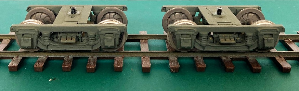 And here is how they look attached to the baggage body with the roof temporarily in place: 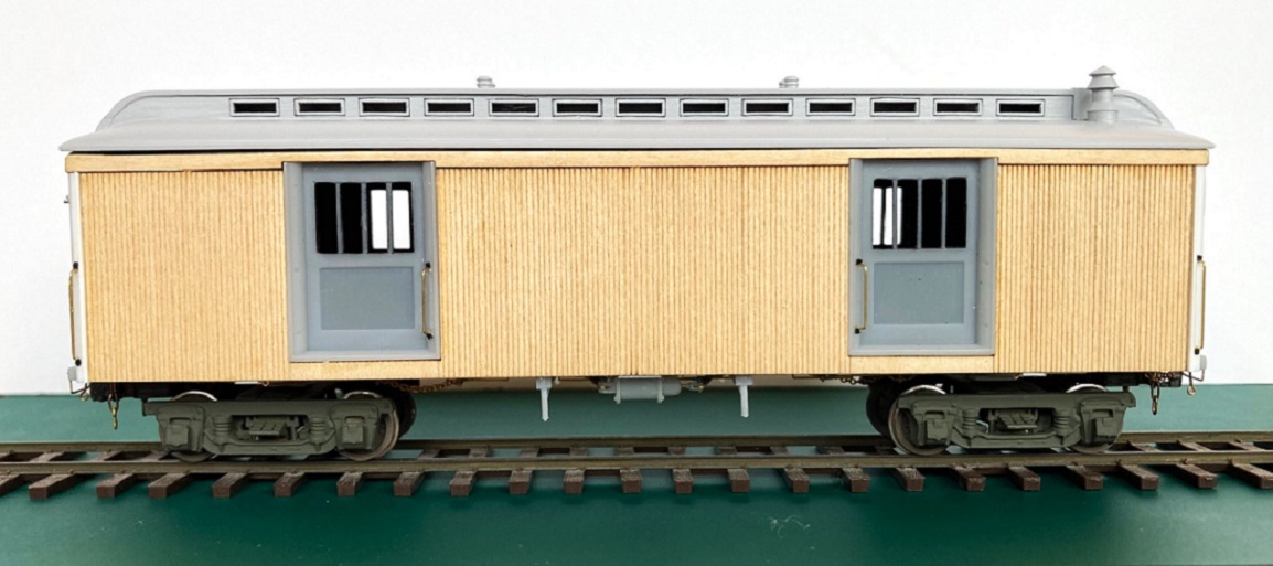 I ended up going with the "black hole" approach with the car interior, painted everything black. I added the weight as one of the Accurail car weights in my stash of parts, epoxied to the interior floor. I did get the car end beams completely drilled. Even installed the safety chains and the brackets for the coupler release levers. And the small brass fitting for the signal cord, above the end door: 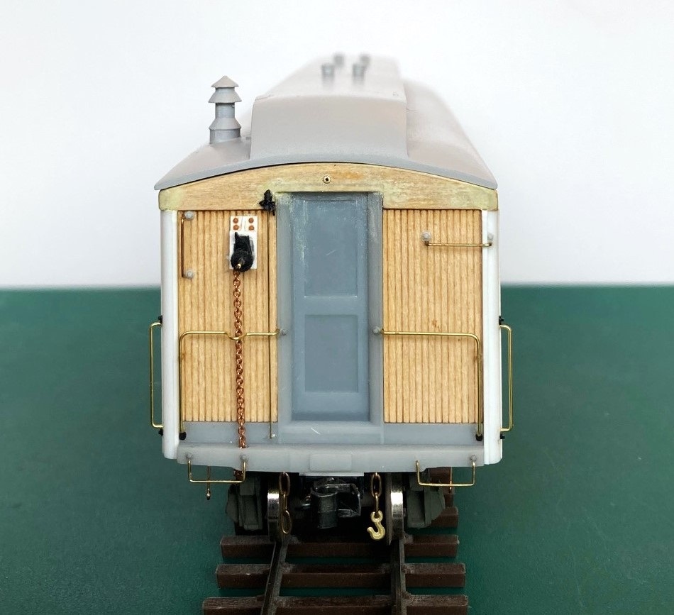 Hopefully, this week I will finish installing the remainder of the underframe parts . . .
Jim Courtney
Poulsbo, WA |
Re: Leadville Designs Baggage/Express 1 in C&Sn3
|
|
Despite decorating and shopping for Christmas, I found time to finish up construction of baggage car 1.
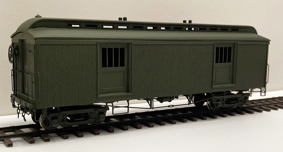
Completing the underframe detailing--the "fourth layer": I used this 1922 Otto Perry photo as a reference for the underframe details:  Truss rods and "keepers": The truss rods were formed by soldering 0.019" brass wire into each end of a PBL brass turnbuckle. Since I've another couple of cars that will use the same needle beam spacing, I constructed a bending jig. After the final bending and trimming, the truss rods were glued to the queen posts and to the floor at the inner edge of the bolster. The "keepers" (my made-up word) were formed of 0.010" wire and installed. Their purpose seems to keep the truss rods up snug against the queen post end, and to keep them from moving laterally during a derailment. They were bolted to the floor at the inside edge of the needle beams: 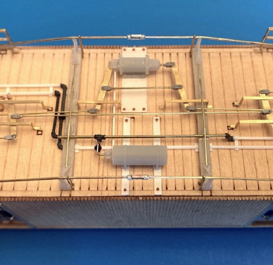 Corner stirrups: The etched strips in the kit fold up to match the corner stirrups in Ken Martin's plan exactly, 12" square in dimension. However . . . the corner stirrups in the photos are not square, rather they are taller rectangles. I formed mine to measure 12" x 15", in a folding jig, so they were all uniform. Before gluing to the floor and end beam, I drilled #80 holes in the little feet. After gluing in place, I drill through these holes into the resin end beam and the wood car floor, inserted small pieces of 0.012" wire and glued them in place with ACC. I hope this "pinning" will keep the stirrups from falling off, if bumped. Baggage door side steps: These are formed from a beautiful set of fold up etchings, the outer frame that curves outward from the underfloor mount (so as to be flush with the car side) and the middle step, with two small end folds to be attached to the inside of the frame. The outer frame protrudes down, 16 scale inches below the car floor. The instructions say to glue the middle step between the two sides of the outer frame. I pondered how I wanted to do this, as these steps protrude more and are more fragile than any other detail on the car bottom. The attachment needed to be: a. Square relative to the sides of the frame. b. Uniform for all four steps, the middle step 8 scale inches above the bottom. c. Sturdy and permanent, so's not to ever have to repair a broken middle step after painting. Since the pieces are 0.010' by 0.030" brass, I decided to solder them together and built a wood soldering jig to keep each piece aligned: 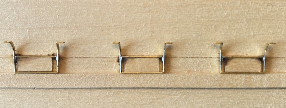 Short pieces of S scale 2x8 were glued to a small wood block as spacers, and the middle steps held in place with tweezers as a hot iron was applied to the fluxed joints, using a small dab of Carr's soldering paste. When the steps were carefully removed from the jig and cleaned up with a fiberglass eraser, they looked like this: 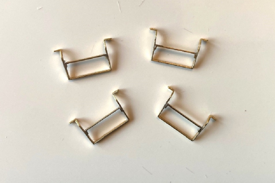 The floor has little marks for locating the steps, but are centered under each door. The Perry photo shows the steps to be offset, toward the center, under each door. The little mounting feet have a hole etched into them. When the steps had been located and glued to the floor with ACC, I drilled #75 through the holes, well into the wood floor. Grant #98 NBW with a long cut sprue were used to "pin" the steps, with MEK flowed into the wood to secure them in place. This is how they look on the car from the side: 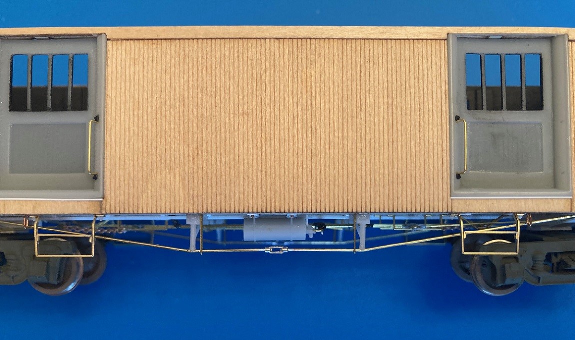 The only other underframe detail is the rings for the attachment of the truck safety chains. Unlike other C&S passenger cars, these were ovoid in shape and were open to the ends rather than the sides, best seen in this photo: 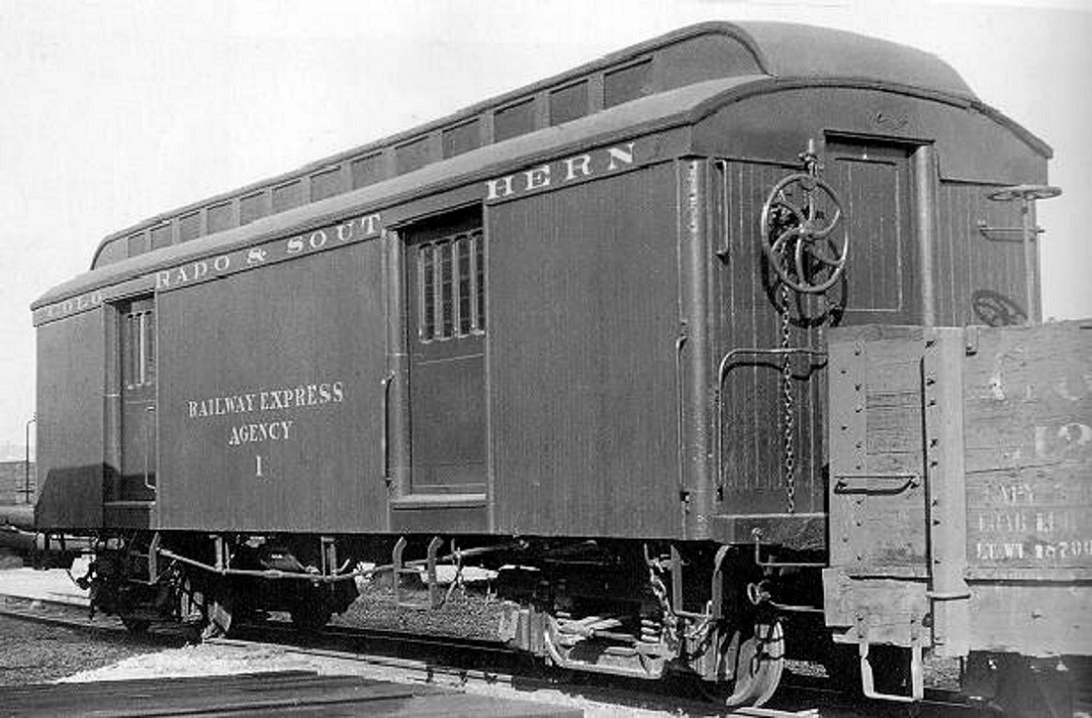 I fabricated these oblong rings of individual links of chain, using tiny etched brass eyelets to attach them to the floor, hoping they don't get bumped off. Here is the completed underframe: 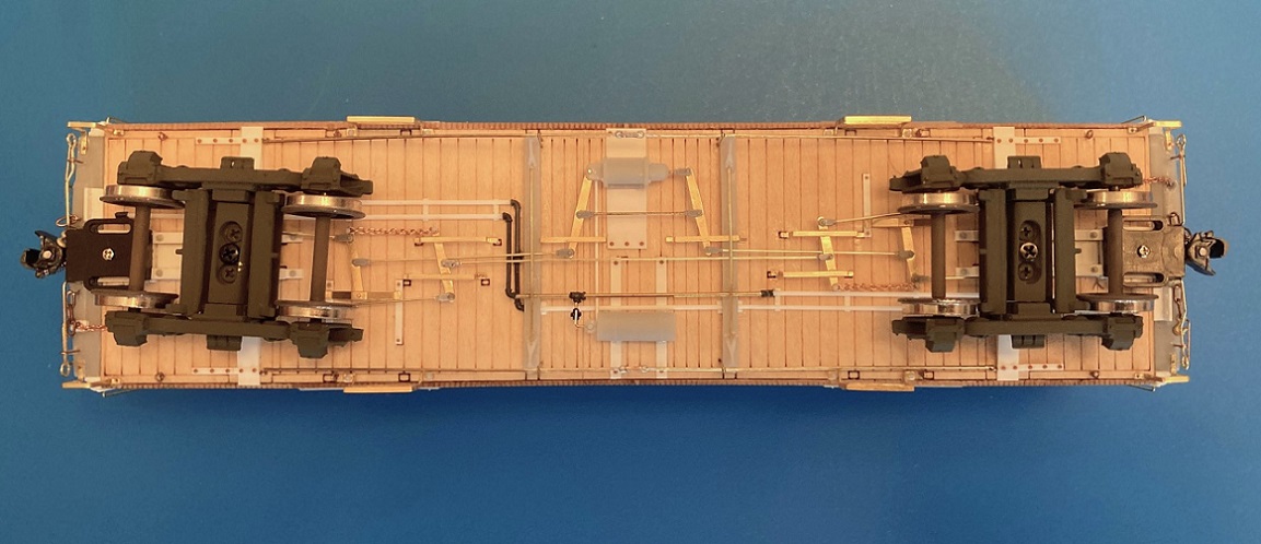 Finishing the ends: Not much left to do. I fabricated mounting fixtures for the brake and signal air hoses from styrene channel and mounted them just behind the end beam. Uncoupling rods, with their ringed ends, were formed from 0.015" wire, then mounted to the end beam with long stemmed eyelets. Finally, the big brake wheels were glued to the shafts. As requested, here is the completed baggage car, waiting for primer and a color coat: 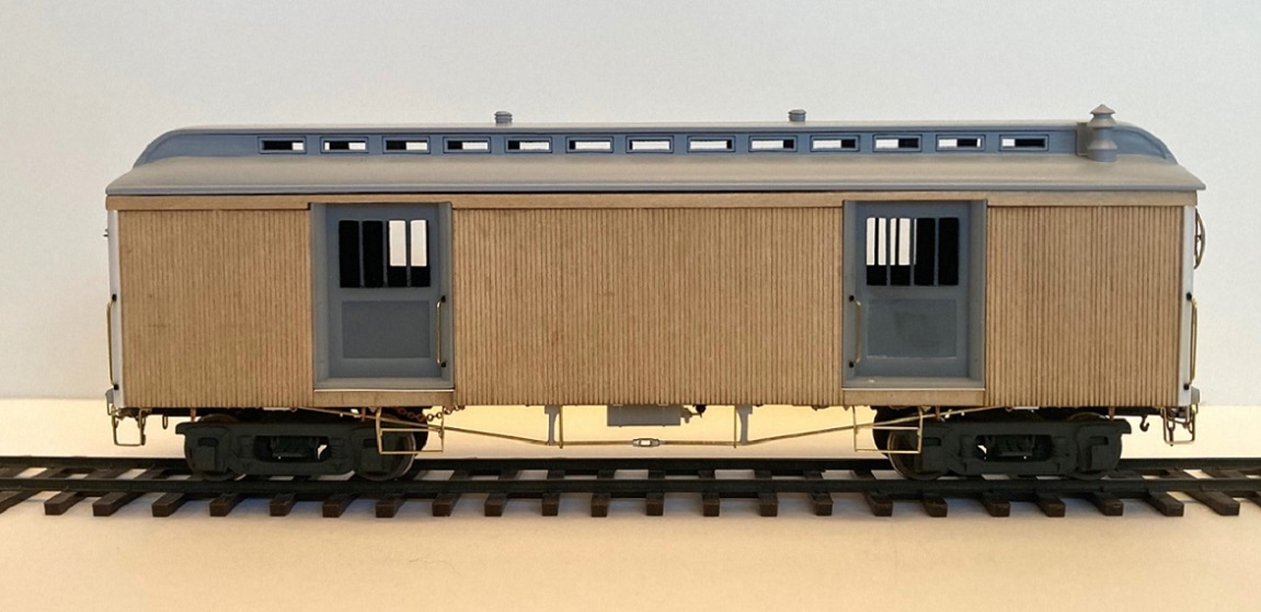 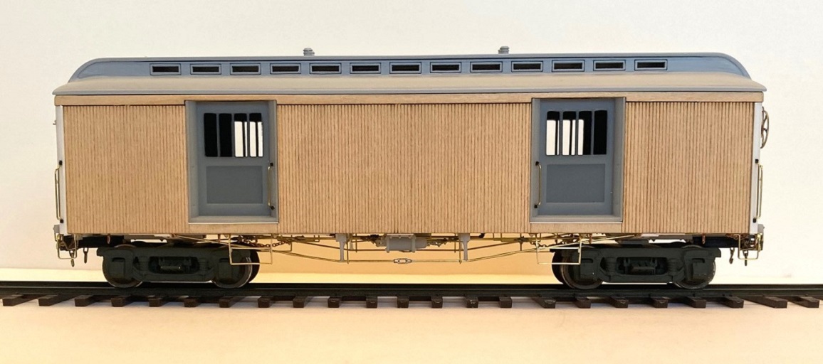 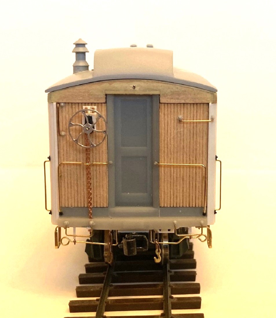 Hopefully, my next post will feature a green baggage car with gold lettering . . . there are still 12 days before the New Year.
Jim Courtney
Poulsbo, WA |
Re: Leadville Designs Baggage/Express 1 in C&Sn3
|
|
Color For Christmas!!
  Off to Christmas Eve services . . . more to follow.
Jim Courtney
Poulsbo, WA |
Re: Leadville Designs Baggage/Express 1 in C&Sn3
|
|
Jim,
Looks great! Can I say I’m “green with envy?” Really looks good I’m glad you shared all of the work in progress photos. There is a wealth of information for us in them. Take care and thank you. Lee Gustafson |
Re: Leadville Designs Baggage/Express 1 in C&Sn3
|
|
Finishing Up
 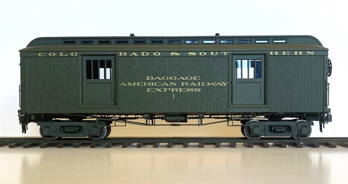 Paint: The body of C&S 1 got a primer coat of Tamiya fine grey primer. I wasn't happy with the finish on RPO/Coach 43 using enamels. So, I finally found an alternative match for Mike Trent's "Dark Green" with the same FS number of 34079--AK Interactive "Forest Green", RC027, one of the "Real Color" paints in their WW2 armor color line. AK "Real Color" paints are acrylic lacquers, similar to P-B-L's "Star Paint" line, that I've used in the past. The solvent is a combination of alcohol-like chemicals, with little odor. I watched several YouTube videos on airbrushing this line of AK paints. It can be thinned with a variety of thinners, I used Mr. Color thinner. I was surprised that it is recommended that the paint be thinned at least 50:50 for use with an airbrush, others recommending 30:70 ratio of paint to thinner. I used a medium tip at 25 psi. The paint went on very smoothly, no need of a retarder. It is dry to the touch in 2 hours, with a matte finish (unlike the enamels I used before which took 2 weeks to fully dry). Did I mention that I really like this paint? The body then received a coat of Testers "Glosscote" for the application of decals. The roof got a coat of "Dullcote". Geoff Hamway, in a recent issue of his Telluride Journal, observed that Testor's has a "New Coke" thing going with "Dullcote" in a rattle can. It isn't dull anymore (is nothing sacred?). Fortunately I have a large stash of the stuff form 15 years ago for use in an airbrush, so I used that. FWIW, these are the painting handles that I've been using for the past couple of years: 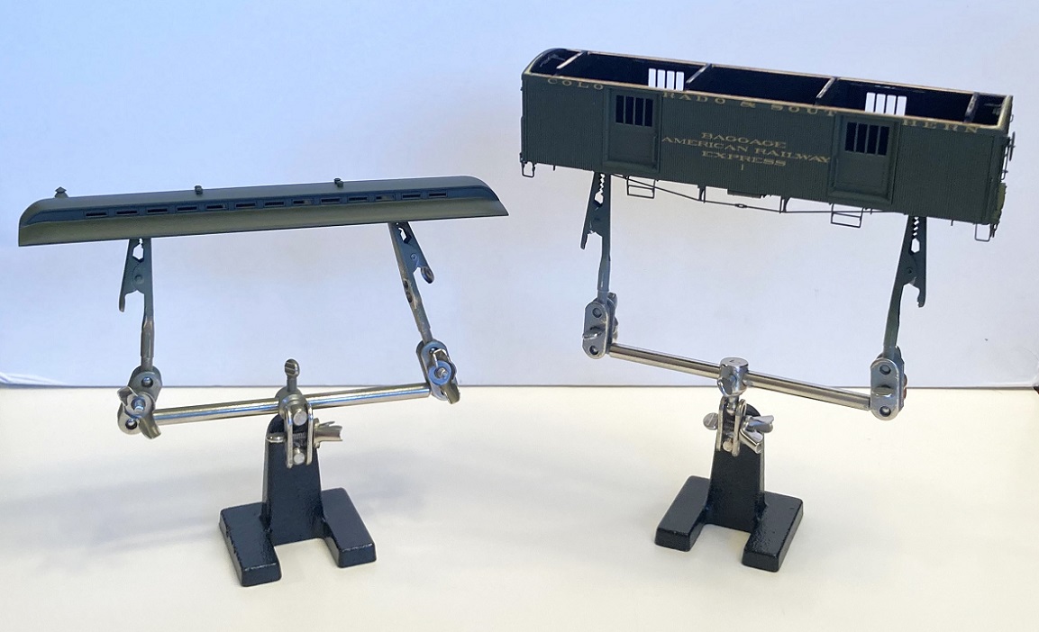 Not my idea, don't remember where I first saw it. They are basically "Third Hand" soldering stands that you can buy at the hardware store or online for $10.00-12.00 (example: https://www.amazon.com/dp/B08Q3NNHNB?ref=ppx_yo2ov_dt_b_product_details&th=1) I ditch the magnifying glass, and orient the rods with the alligator clips vertically and attach the clips to temporary screws in the bolster. Lately, I've been leaving the car body on the stand from primer to color coat to gloss coat to decaling to cover coat to dull coat. No more accidental finger prints in soft paint from handling. Lettering: Included in the kit are decal from Bill's own artwork, printed in buttery "Deluxe Yellow":  The decals are perfect for the late 1920's until abandonment. Unfortunately for my C&S #1 project, part of a 1924 consist, "Deluxe Yellow" hadn't arrived yet, the lettering still gold paint. I've never found a date for when the C&S began substituting Yellow paint for the Gold used on passenger car lettering (Danneman cites January, 1925, as the date the D&RGW adopted yellow paint for lettering its passenger cars). So, I used Thinfilm Sn-28 "C&S Passenger Car Set", the same artwork that came with my Overland coaches. I used the "Colorado & Southern" from the set for the letterboard side fascia. A further issue is that in 1924, the C&S baggage cars still carried the WW1 / USRA era "American Railway Express" lettering, and the word "Baggage". The only photo that I've found of C&S baggage car 1 in the 1920s is this photo of the Leadville passenger train at Dillon: 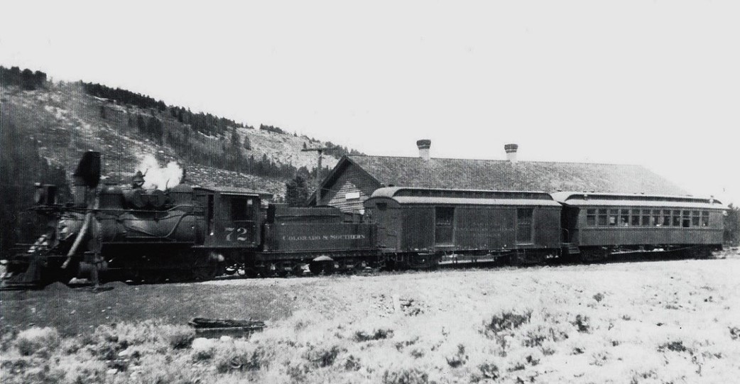 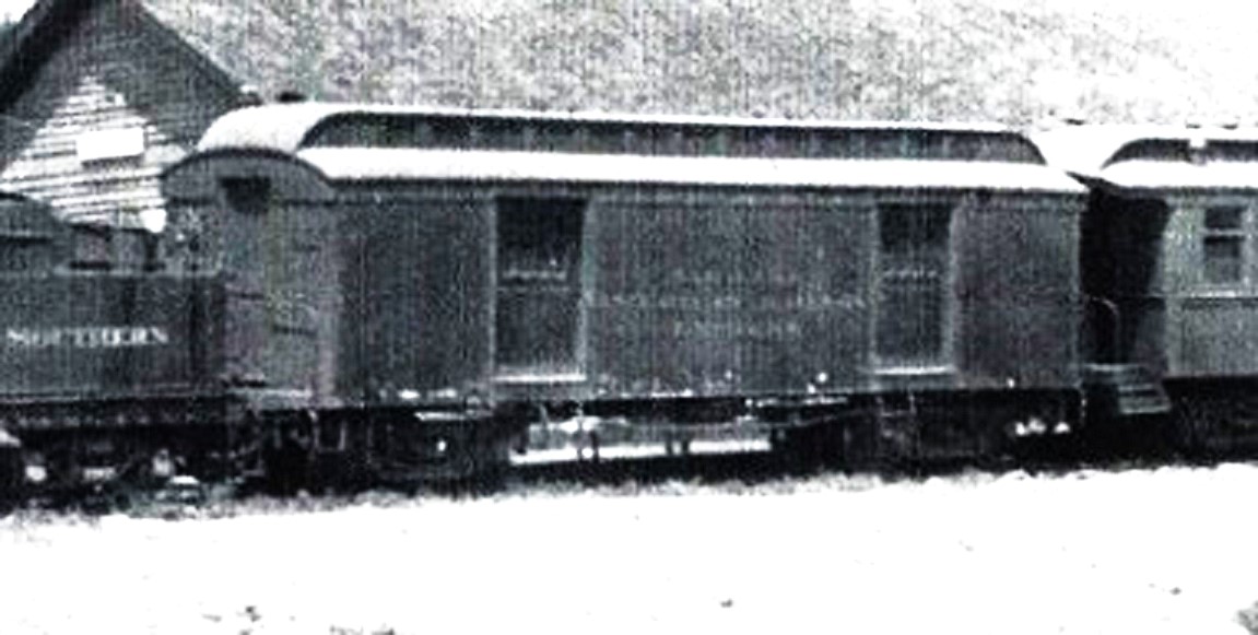 The words "American Railway" barely fit between the two side doors. To reproduce this lettering I used Thinfilm's set Sn-04 "D&RGW NG (Rich Gold) Set" (https://thinfilmdecals.com/narrow-gauge-decal-list/. This set includes the words "Baggage" and "American Railway Express" in the same 4" extended Roman font and the same gold ink as the C&S passenger set. I had to cut apart the L-W-A-Y of "Railway" and rearrange them to make the lettering fit, but it does, just: 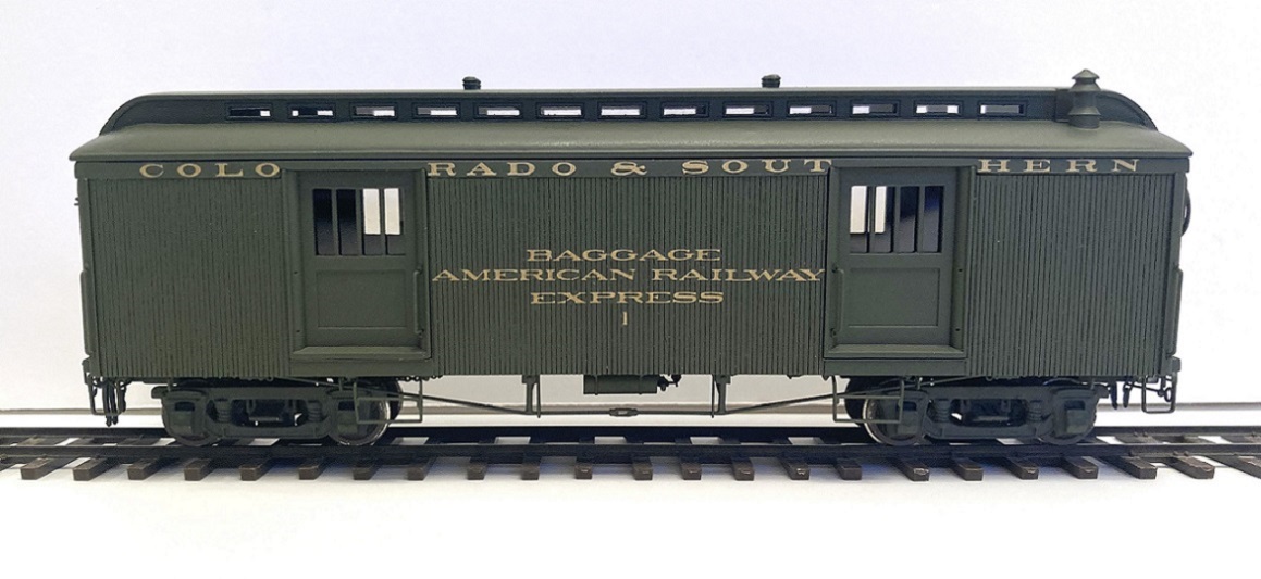 The body got an overspray of Old Dullcote after the decals were dry. The Dullcote minimised the visible wood grain of the siding. And I doubt that the "varnish" was highly varnished by the 1920s. Finishing touches: P-B-L rubber air and signal hoses were installed on the car ends, along with the couplers. The baggage door windows were glazed with microscope cover slip glass, attached to the inside with dots of clear epoxy. The clerestory windows were glazed with strips of Evergreen 0.010 thick clear styrene. So the car is pretty much finished:  I haven't glued the roof to the body yet, the final step. I'm toying with the idea of installing safety bars behind the glass in the baggage doors. I'm not sure they will even be visible with the black interior and the reflections from the glass. Here is how baggage car 1 looks coupled ahead of RPO / Coach 43. The two head end cars handled the express and mail business on the South Park Division in 1924: 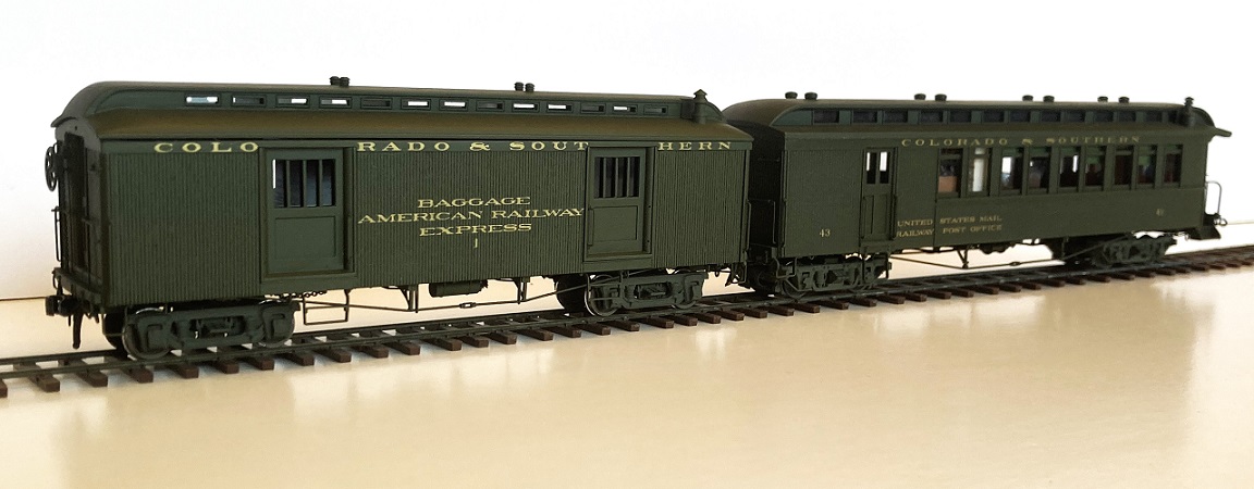 Bill's kit for C&S 1 is a very challenging kit, a true craftsman's kit. But it can be built up into a fine model. I am very pleased with how the baggage car has turned out, a car that I've always wanted to model, another thing to check off the bucket list. If others build up Bill's kit, especially in HO or O scales, please share photos of your work here! 
Jim Courtney
Poulsbo, WA |
|
|
Superb modelling as always. Paul R.
|
Re: Leadville Designs Baggage/Express 1 in C&Sn3
|
|
In reply to this post by Jim Courtney
Jim,
Yes, outstanding modeling. The use of multimedia, additional details that enhance the kit, the skill to combine all of those elements in a craftsman kit to produce an excellent finished model. Thank you for sharing the work, techniques, problem solving approaches to produce a beautiful and accurate model. Lee Gustafson |
«
Return to C&Sng Discussion Forum
|
1 view|%1 views
| Free forum by Nabble | Edit this page |