Flanger 015
1234567
1234567
|
No other project in model railroading strikes more fear in a modeler than making a symmetrical snow plow. Out of brass. It is surprisingly easy.
We subbed this project out to Hayes Heavy Industries, otherwise known as the garage. 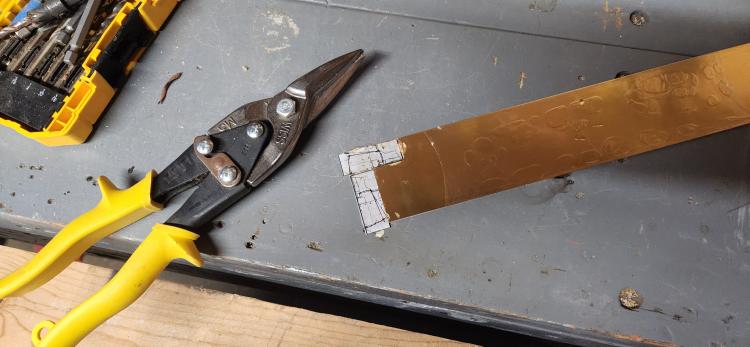 Mike Trent generously provided a pattern for the blade. The blade is actually 3-4 parts. I elected to make the base part out of brass sheet. My local hardware store had 0.016" thick brass. I examined my supply of adhesives and selected canopy glue to adhere the pattern to the brass. Then I used the tin snips to rough cut the sheet to shape. The rough cuts were Then shipped back to Leadville. 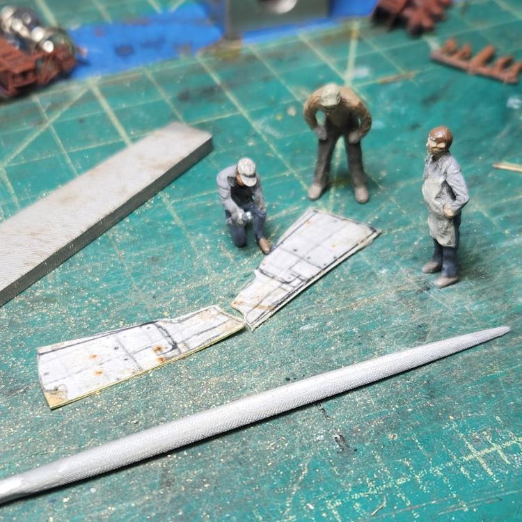 Using hand files and my trusty vise, the parts were clamped together and filed to shape. This took practically no time. I returned to the garage to shape the blades and found all I need was a pair of pliers and my thumb. Easy! 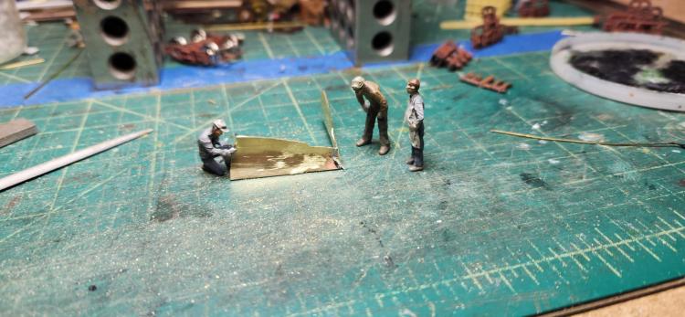 I washed the parts, did some test fitting and figured, what the heck! and fired up the soldering iron. Using a weight, I clamped the blades to the weight, tinned the miter and bang! A flanger blade. 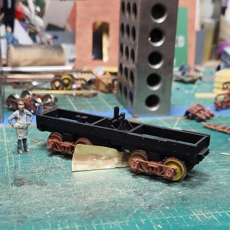 It took me longer to write this post than to do the job. I am surprised at how easy bit was and how well it turned out! 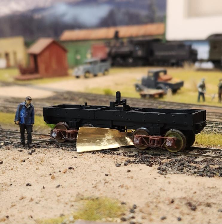
Keith Hayes
Leadville in Sn3 |
|
Administrator
|
Nice! You're off to a great start. And the brass adds a little weight, which is always good.
|
|
Keith loves to pose his figures alongside in a wonderful manner, perhaps channeling John Allen.
 Taking that approach, looking at the expression of the Trainman on the left.... Hmmmmm  Denver Public Library OP-6190 by Otto Perry. 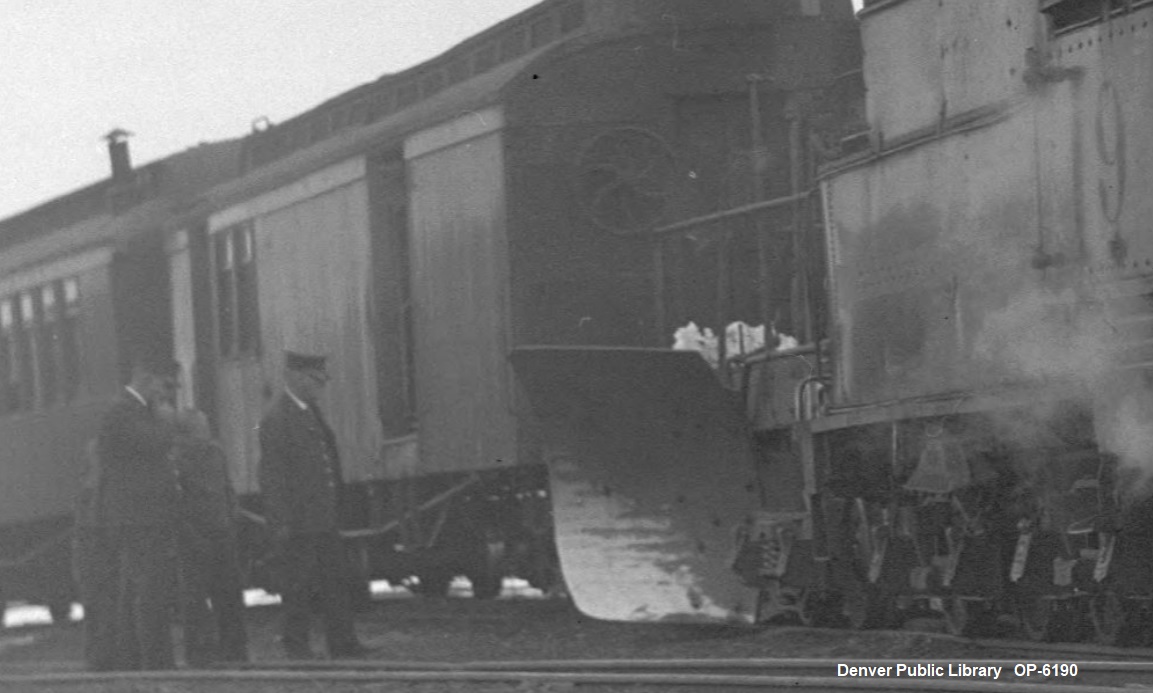
UpSideDownC
in New Zealand |
|
Administrator
|
Interesting picture. This is the last Passenger Train to Leadville. 4/10/37. #60 and the Boxcar have been taken off at Como and #9 and a flanger, which is 015, has been put on the train. It looks to me as though the right side blade has hit a rock at some point and is somewhat bent, but still operational. Flangers lived a tough life. The crew, including Conductor Tom St.John, appears to be watching as the air hose is stubbornly connected to the train. Curley Colligan waits in the cab.
Mal Ferrell, in C&Sng, does not have a picture of this, but does mention that #9 and a flanger were added to the train at Como. And here it is. Thanks, Chris. Another bit of history for the archives. Here is the full image. OP-6190 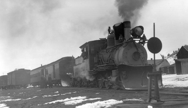
|
|
Otto shot several other views that survive enlargement to provide relevant details of the obscure.
 Denver Public Library OP-6191 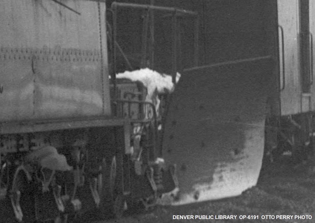 Denver Public Library OP-6195 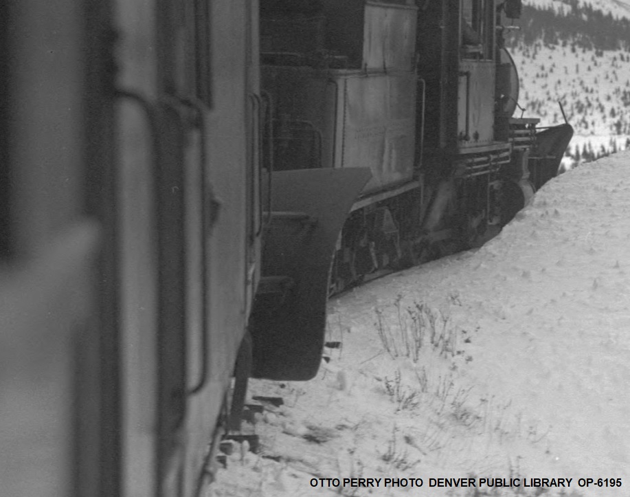 Denver Public Library OP-6194 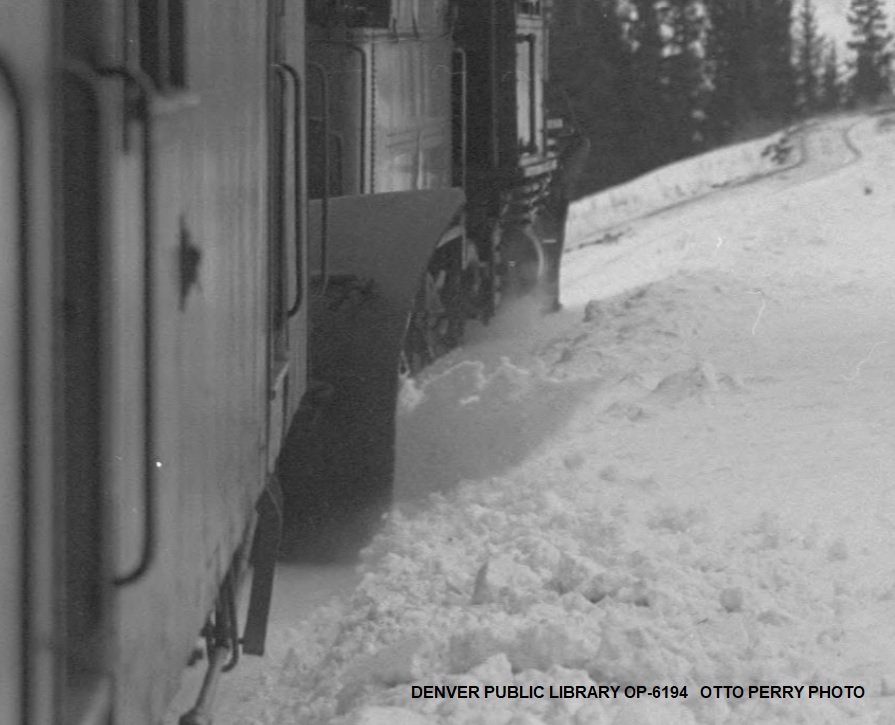
UpSideDownC
in New Zealand |
|
Administrator
|
Wow! Thanks, Chris. This is very helpful. First, I see no damage to the blade, it must have just been the angle of the photo.
The second thing of interest is that the body of Baggage and Mail Car #13 is listed at 8' wide. The reach of the blade appears to be 12" beyond the side of #13, which means the wings of the blade extend 10' before the upper outward curve. I've never seen these pictures, but somehow I must have determined the width of the blade correctly at 10'. There is a picture in the "Pictorial Supplement" which shows the rear of the flanger straight on, parked outside the Rotary shed at Como. I probably compared the known width of the body and the 3' gauge of the track to the width of the blades. But I'd like to have confirmed that from these photos, and it does, very clearly. Thanks again for your dogged determination! And thanks to Ken Martin for his C&S Passenger Car Book. An excellent resource. |
|
I'd forgotten to add the other one, with a much clearer blade brace attachment point visible. Because I just know Keith will be asking about that detail next....
 Denver Public Library OP-6192 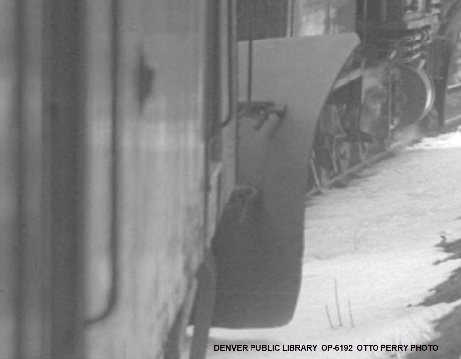 The right side Blade does have a couple of puckers on the lower edge, most likely from backing up and striking rocks from the looks of it. The multiple horizontal crease marks are from the bending press operation to obtain the curve in the heavy steel plate.
UpSideDownC
in New Zealand |
|
Administrator
|
Thanks! I have the upper brace but not the lower one. Never saw it. Yeah, he will like that!
|
|
In reply to this post by Chris Walker
Thanks, Chris.
Yes, John Allen is an inspiration, and I guess Ken Patterson too. The NMRA recently posted a video of a presentation on The Gorre & Daphetid that shares many details I was not aware of. John used photography as a tool for modelling and did not consider the photos precious. I find a good location, grab some my people and stage the photo. It is that quick. The flanger blade was a delightful surprise. I was not looking forward to fabricating this and it took 30 minutes tops, plus waiting for the glue to dry. I will add on the other blades using styrene. Chris the photo is very helpful as I am nearing the point where I need to plan and fabricate them. The rivets on the blades tell a whole story themselves! D&RGW flangers have two braces, and the photo gives further credence to the idea that all the flangers share the same heritage. I could be mistaken, but I think the image of Tom St.John on the ground has the train going eastbound. Boreas Mountain rises to the rear, and I recall all the structures here are on the east side of the tracks, opposite the stone engine house and wye. I don't recall seeing the flanger on the train upon arrival in Como, but my eye is always on the sad engineer walking towards the roundhouse. 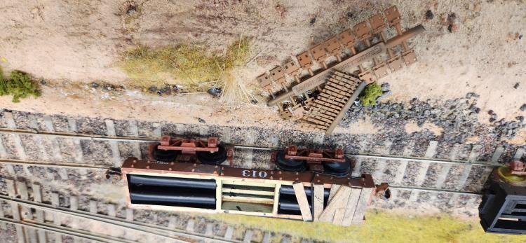 Mike, I have a plan to stash some brass inside the frame to add some weight. This has already been tested on 013. The remaining fussy brass subassemblies are the handrails, the blade signal, and the end stirrups. The rest is smooth sailing!
Keith Hayes
Leadville in Sn3 |
|
This post was updated on .
Glad to help(or frustrate) you Keith.
 "I am nearing the point where I need to plan and fabricate them. The rivets on the blades tell a whole story themselves! D&RGW flangers have two braces, and the photo gives further credence to the idea that all the flangers share the same heritage. " If you go back to pg1 of this thread, or to the NGPictorial, and review the photos, it is quite clear that the Blades visible on the D&LG versions followed that of those of the D&RG, except the 015 now has very tall blades that keep the sheet steel look with little shaping at the corners(unlike those of the D&RG). Seems it got rebuilt at sometime later. Those blades you showed don't reach up anywhere near the top of the mainframe. The D&RG flangers varied alot: some having single, some having doubled bracerods, one(OJ) flat steel instead of round bar before final iteration and then there was a different style of forming the eye of the rodends, however they all seem to brace at the centre of the blade. NGPict vol-VII shows the whole lot.
UpSideDownC
in New Zealand |
|
Administrator
|
He will add those plates later. There are three or four plates added to each side. And the cutting blades.
|
|
In reply to this post by Chris Walker
(Due to some Nabble funkiness, this will be four posts)
You all have taught me to study the photos closely. Our digital scans allow us to greatly magnify the shadows and better understand the details. Mike McKenzie was kind enough to share a slew of photos of D&RGW OC at the CRRM. All the D&RGW flangers were rebuilt with steel frames and bolsters. Sloan illustrates (courtesy of Eric Bracher, I believe) all the D&RGW flanger blade configurations. Each flanger was assigned to a different location, and the blades must have been modified based on train crew experience. OC has one of the most simple blade shapes. 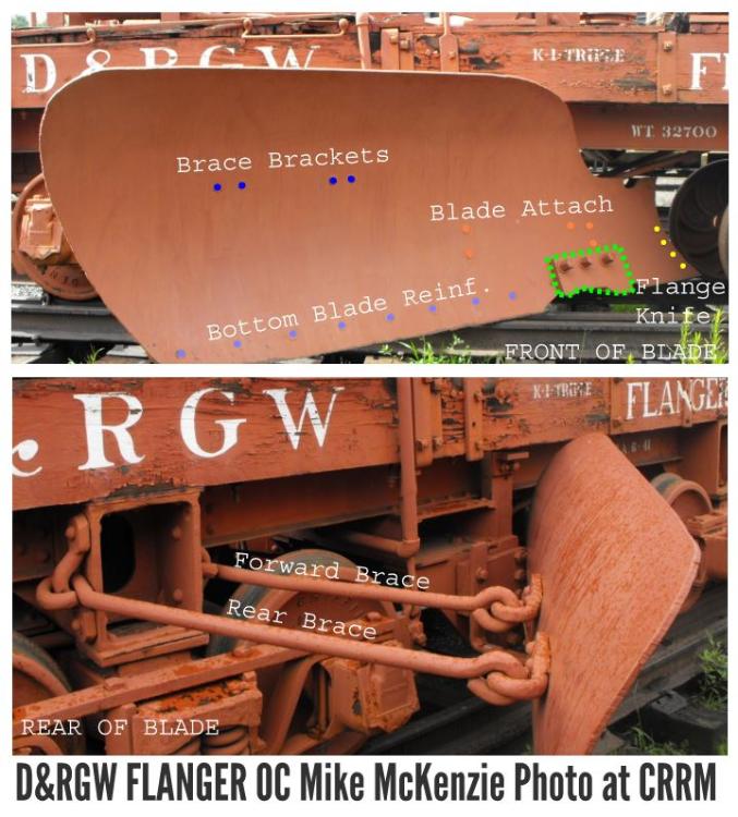 This image shows the front and rear of OC's blade, and the various rivet/ bolt locations. OC seems to have a single blade, two braces--forward and rear--and some reinforcing along the bottom of the blade. The orange dots above the knife are where the blade is attached to the moving frame (you could call it a guillotine) and the yellow dots are where the two blades are bolted together. Most all of these are rivets that are filed flush with the face of the blade on OC.
Keith Hayes
Leadville in Sn3 |
 Stepping back a bit, the blade is attached to a bracket at the base of the blade frame (or guillotine) that allows the blade to be raised and lowered. The guillotine pushes against the lower bracket mounted below the sills and the upper bracket mounted above the sills. An air cylinder below the live end of the lever attached ot the guillotine via the yolk allows the blade to be raised and lowered. Should air not be available, there is a manual bar with cams on the ends. The one on OC is remarkably similar to that on 015.
Keith Hayes
Leadville in Sn3 |
 Here is 015. Previously I had thought there was a single brace, as only two bolts were visible. Chris has proven to us that two braces are located above one another on the rear of the blade! The orange dots indicate locations where the new, large outboard blade is connected to a second blade. The flange knife is noticeably absent in the Jackson photo. Mike Trent believes that the Priest flangers on the locomotives obviated the need for the knife on 015, and it was removed and the blade placed in the lowered position.
Keith Hayes
Leadville in Sn3 |
|
This post was updated on .
 Chris rightly points out that my brass blade looks nothing like the blade on 015. Yet. I chose not to model the blade as part of the 3d print, partly because the shape is complex and would likely be very fragile. Intuitively, making it out of brass seemed smarter, and I knew that the 015 blade had multiple parts. There seems to be an 'original blade' shown in yellow. This is bolted to the blade on the opposite side and the guillotine frame. I think use dictated a second blade was added (shown in green). The profile of this blade more closely matches the flanger frame to keep snow off the rear truck, and allow higher drifts to be cut. But it was not high enough, nor did it spread snow far enough away from the track, so a third blade was added (in blue) This blade is about 48" tall, and extends a couple feet further from the side of the car. It appears to me there is also a reinforcing blade at the bottom edge (in orange) that frames the knife location. I will build these added blades from styrene, and use Tichy rivets, NBWs and Archer rivets for the attachment points. Thanks for the reminder of the photo of the flanger in Como in the Pictorial Supplement. My copy has the full image, and the flanger is small and the contrast is high, so there is not much detail. The photo is credited to DPL, but I don't see it there. The quality of the photo and the light makes me think this was taken during the Denver Water Board tour. Lastly, I apologize for the upside-down photos. When I turn my camera upside down to get the lens at scale-eye-height, evidently, the file is like a weighted contact lens and thinks the other side is up. The RAW data seems to fool the phone's photo editing software, too.
Keith Hayes
Leadville in Sn3 |
|
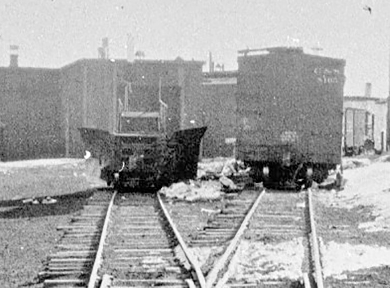
Is this the Como photo in question? My print was copied from a print that Ed Haley had. It's still pretty grainy and contrasty, but may be a bit better than the screened copy in the book.
|
|
Awesome, Todd!
Keith Hayes
Leadville in Sn3 |
|
This post was updated on .
Hi Keith,
Sorry; I was assuming you were modelling the Blade as one piece given the small scale you work in, maybe with scribed lines for the joints. I've modeled in large scale for 30+ years(and the past 15 have been full-size), that lead me to reworking my approach to fabrication of items in an actual prototype manner than in the small scales. Those Otto Perry pictures of the Flanger in operation on Boreas, show the Blade both raised and lowered in the sequence of images. And I'd say the Como shot may illustrate the testing of the raise/lower of the Flanger after adding it in; I doubt they'd take off arunning for the Pass without ensuring all is well with it(just like the required Brake Test). Apart from the Engineer, all are looking at the Flanger. I'm really intrigued with those hidden Braces construction: I looked at the termination of the top brace which appears to be very heavy cross-section opposed to the D&RG round rods. If I was to speculate, I'd be thinking it takes the form of an inverted L, or more likely, a T with rod for the pin. I've probably been around Mining too long and the common use of repurposed Rail section(30lb?), but it has those characteristics in appearance, both upper and lower arms. see OP-6192 and OP-6195(at full enlargement) in the DPL. Your speculation on the Train's location at Como is confirmed by Otto's leftside portrait OP-6191. The Denver Water Board photo of the Flanger at Como is also on pg83 The Mineral Belt V II, and attributed to Colorado & Southern Railway, Ronzio Collection. EDIT: and in Goin' Railroading, Mike. 
UpSideDownC
in New Zealand |
|
In reply to this post by Keith Hayes
Flanger frenzy (As Mike has dubbed it!) continues.
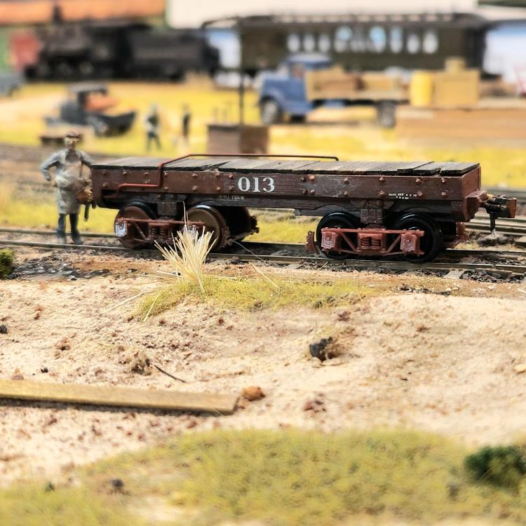 The idler is nearly completed. I ordered the correct truck from Shapeways a couple weeks back, so the question is, "did they make it into a box before the mailing clerk got their yellow slip?" A week will tell. The shop crew is employing super large clamps to assemble the blades. 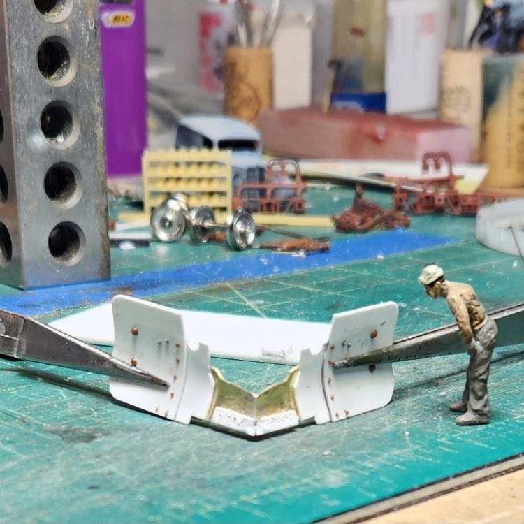
Keith Hayes
Leadville in Sn3 |
|
Administrator
|
By George, you've got it! It's downhill from here, Keith. Beautiful work.
|
«
Return to C&Sng Discussion Forum
|
1 view|%1 views
| Free forum by Nabble | Edit this page |

