Flanger 015
1234567
1234567
|
Administrator
|
This post was updated on .
Impressive!! Is the boot at the bottom set in the raised position? Just had to ask. I remember having to fiddle a while with that, much later in the construction. There is also a fixed anchor bracket in the well which secures the rear of the lift lever opposite of the cylinder. That can be easily fabricated if it's too late to add to your final drawing. This is visible in the D&RG drawing. It sits on a steel plate which spans the middle sills.
I am completely astonished and fascinated at this new-fangled process. Blown away, even. |
|
Mike, the 'blade casting' was the most difficult part to model due to the shape of the web that holds the blade. It took pondering overnight, but I got it figured out. I was going to model that part loose, but in the moment, I figured, "Just make it part of the model." So I did and put it in at about the height in the drawing. We shall see how that works out with the part when it comes. The test frame has the coupler at about the right height on D&RGW trucks. I have some PVC trucks for 015 and some San Juan trucks on order for 013. No, Jim the 013 trucks are not quite right, but they are brass and will add some weight to the idler car.
By the time I got the blade casting done, I was so anxious to submit the part to Shapeways I forgot the dead bracket. As you say, it is easy to add after the fact. When designing this, I am making decisions about how I want to build the model and what work I think will be easy, or be easier, to fabricate. The part is designed to have a wooden bottom deck and top deck; the handrails and air lines will be fabricated from brass; Kadee couplers and springs will slide into the coupler pockets; I will fabricate the lifting mechanism and switch stand. All this could probably be modeled as part of the 3d print, but the part would be very fragile, and the 3d-printed deck would not look like the wood deck will. Those are my decisions, so if I post this for purchase, you have to abide by what I have decided. The part did get posted successfully to Shapeways. I submit a stereolithography (STL) file, and then the website mulls this over for a while and either tells me there are problems or says it is on the way. The posting process has improved and I am getting less errors--when you work in the virtual world, it is really easy to think you are drawing in one plane when you are not--ask me how I know. I think the only error might be that the web of the casting behind the flanger blade is missing. If this is so, it is a pretty easy fix. I got an email that the part passed the human review and is on the way to print. We should all know in about ten days....
Keith Hayes
Leadville in Sn3 |
|
Administrator
|
I continue to be amazed with the process. The drawing shows the blade and the mechanism in the lowered position. You may need to sand the bottom of that boot to 3 or 4 inches above railhead. But you can't know how far until you have your trucks. Thankfully for me, the new ASF trucks are the same height as the stock trucks from Durango Press.
This is the time we run into with any project, where we have to tweak a little here, compromise a little there, and add a little dash of by guess and by golly and hope it works out in the end. For me with 015, fabricating and setting the blade, the air piping, and deciding what to do with the air tank required the most head scratching. I remember too, having to carve more out the frame to clear the wheel flanges. Keep it up, this is going to be a fantastic model, and I admire all the work you've done already! |
|
While I wait for the new print to show up, I have been working on the first print, using it to model idler 013.
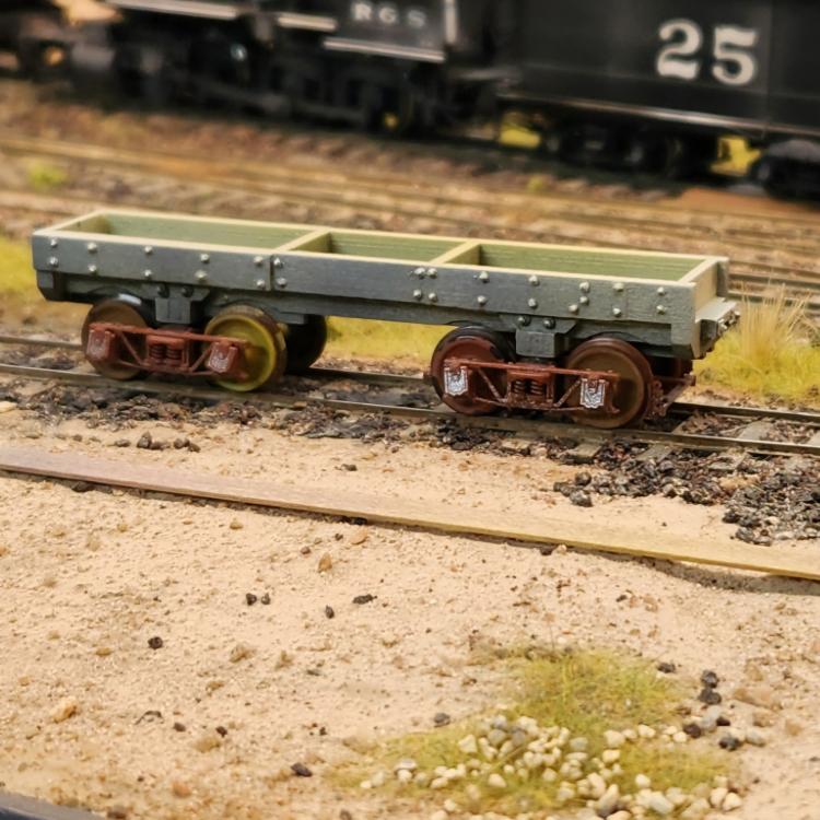 Studying the Dick Jackson photo, 013 has some different details with the blade removed--see Rule 1. I added some nbw detail, primed and painted the car. I see I need to add a couple bits before I get too far along. I wonder if the car had anything but a hand brake at the end?
Keith Hayes
Leadville in Sn3 |
|
Administrator
|
Looks great!!
Triple coupler pockets? |
|
Does it have one? Hard to tell. Is it the 3-way casting similar to what D&RG used on loco pilots?
Keith Hayes
Leadville in Sn3 |
|
Keith
PSC makes a 3-way coupler pocket that is the smell as used on gondolas 1541 and 1688 to move standard gage cars in broad gages trans between Salida and Leadville, 1919 into 1924. Also same was used on 1032 in Santa Fe in the 30s. 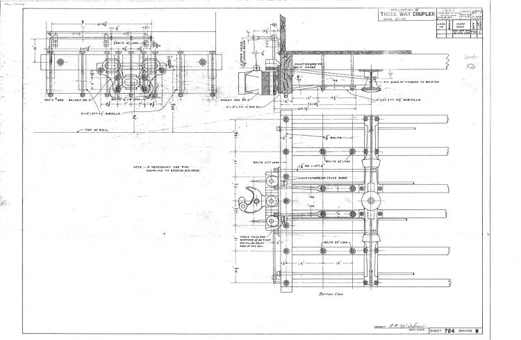
|
|
In reply to this post by Keith Hayes
I don't think so. Where would the "3-way casting" come from in 1934 for an "economy" conversion? Why would it need a 3-way ?.... as the SG-rail at Leadville appears on the same side in the photos I've seen. Enlarged from pg147 Poole/Martin's Narrow Gauge Pictorial Vol. VIII 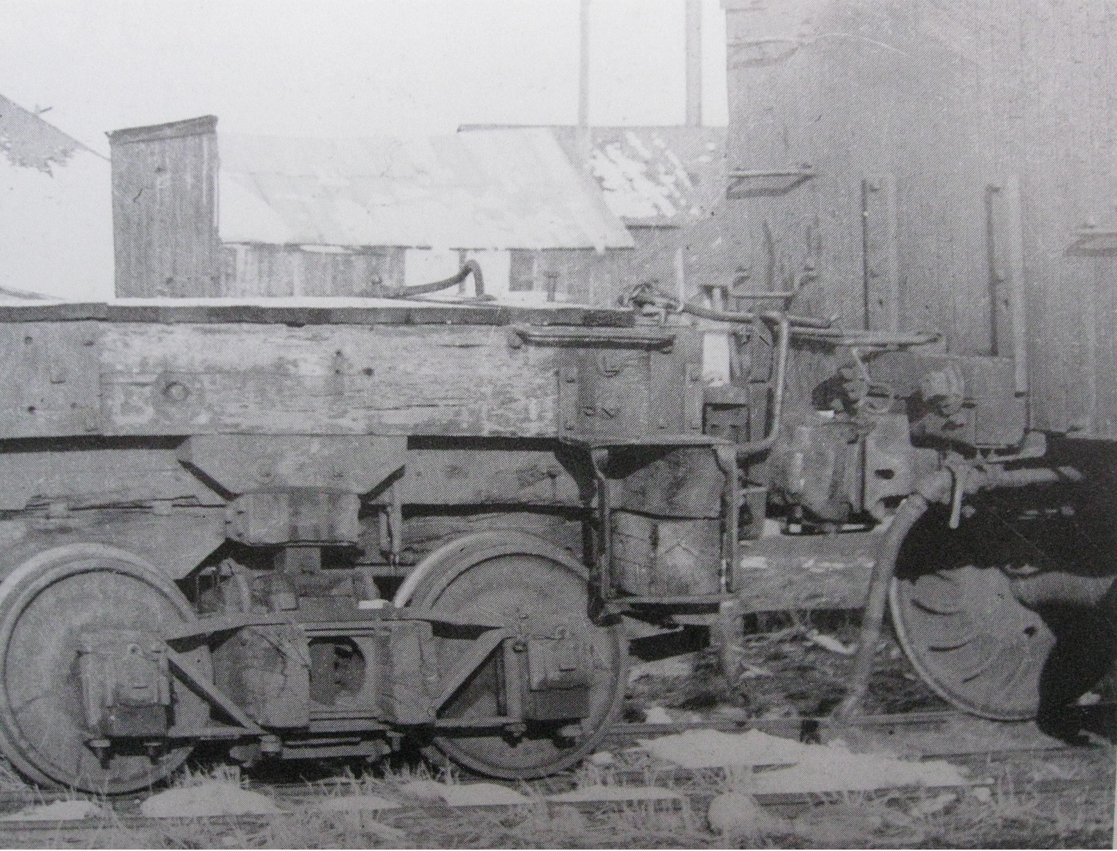
UpSideDownC
in New Zealand |
|
Administrator
|
OK, Maybe no need for a three way then. But if it only has a single on one end it has to be offset and raised for standard gauge. "Economy conversion"! Gotta love that. Pure C&S ingenuity. Well you got me there. Sounds kinda Rednecky. Almost like the C&S followed our cherished Rule 1.
|
 Yep! Kit-bashed! Yep! Kit-bashed!
DPL RR-1266 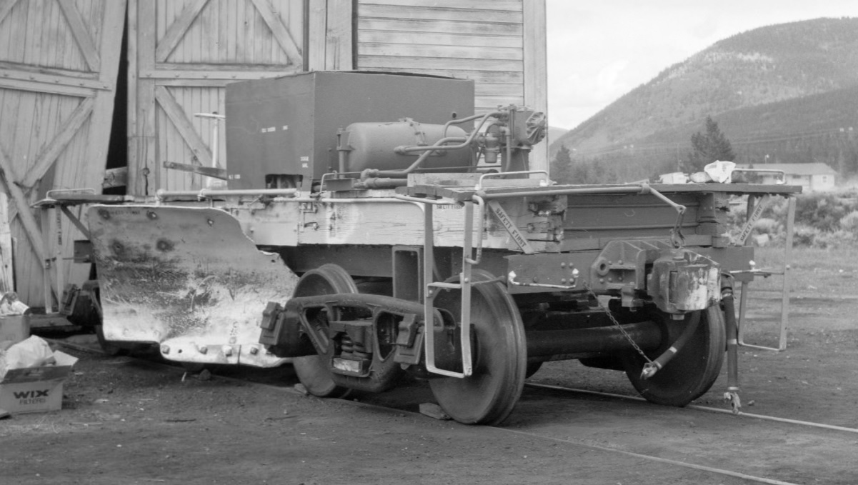
UpSideDownC
in New Zealand |
|
Administrator
|
Is this 013? On Bettendorf trucks? With the blade reattached? This is the "A" end. I wonder if there is a picture of the "B" end anywhere.
I think this is standard gauge. Or, standard gauged. It has a steel bolster beam like a D&RGW flanger. And a gray/black paint scheme like D&RGW. Sure is Leadville. Very interesting find, Chris. Thanks! |
|
I just had the Bob Richardson pic in my archives for yonks.... and thought Keith needs a trio of those things....
 I only had it saved, since it reminded me of a run South years ago and seeing the damage done to the doors of the Masterton Engineshed from the day shift having left a 4-wheel flat outside for some reason(repair?), and an incoming loco crew never noticed it there hiding in the dark when putting away.  
UpSideDownC
in New Zealand |
|
Administrator
|
 I might have known! I might have known!
|
|
In reply to this post by Chris Walker
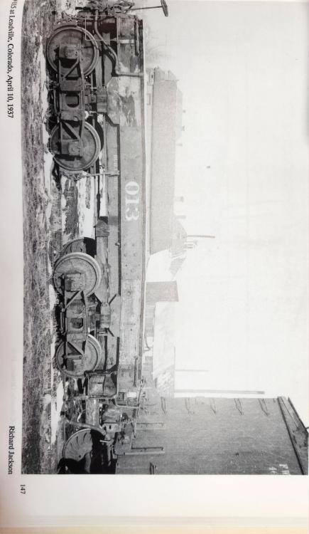 First off, I'm not a railroader, so I will dive into the abyss of the little I know. 1. Couplers are really heavy. I could not lift one myself, and it would pretty much obliterate my entire foot if I were able to lift one and accidentally dropped it. The part we see is the tip of the iceberg: the shaft extends into and under the frame and is bolted to a "U" shaped piece of steel top and bottom. There is a spring for some cushioning, and the weight is, in part, supported by a piece of iron below the shank and behind the head. The rest of the particulars, I have forgotten as it was a dark space under the flat car. 2. Pat, thanks for the reminder of the two gons with 3-way pockets. High time someone model these!!! Note that this casting has a VERY LARGE plate behind it, and the coupler looks like an American Flyer-sized affair with a large shank in the form of an "E" to mate with the pressed cylinder of the casting which forms a "c". A pin would hold this in place, and the knuckle could be moved from one position to the other two, ideally using a engine lift so as to avoid aforementioned foot injuries. Oh, and on the drawing Pat provided, the VERY LARGE plate is firmly attached to MULTIPLE END BEAMS with LOTS OF BOLTS. (During my short stint as a Carman, I observed that wood rolling stock starts with lots of large, solid, heavy pieces of wood that steadily become lighter as they are drilled and carved and filled with lots of holes, mortices and tenons.) 3. Generally the drawbar fits in the gap created by the two center sill pieces, usually about a foot apart on NG equipment. Note on wood cars the ends of the center sills are oak--dense to withstand crushing abuse, and these are fitted to the middle part of the center sills which are spruce, which is good in tension. You can see this splice on your models when you turn the car over and see three bolts on each center sill between the needle beam and the inboard axle. But make sure you don't pick an SUF model by mistake--you will not find the detail there! 4. On the Flanger 013, there are two center sills low on the car, with four more sills above that. There is a single end beam, and not really enough material to hang the VERY LARGE casting on, IMHO. If the shank is moved up for the SG coupler, the center sill would need to be adjusted too. Not to mention, the casting and the American Flyer knuckle might cause the 'A' end of the car to nosedive some. It is hard to tell from the photo if the end sill has been supplemented. 013 no longer has all those heavy castings to move the blades up and down, and it lacks the blades too. Maybe they added a 12x12 end beam below? Oh, the car does have two truss rods, which is about the only thing that keeps the works together. 5. Mental math tells me that the center line of couplers is about 10 1/4" off from narrow to standard gauge. I have to ask, is that too far to push the coupler casting over for an SG car? This does not explain the alignment of the coupler with the FW&D coupler though. 6. The drawing Pat provided has an early date, and 013 was likely modified in the 20s. How many of these castings might Burnham have made? I recall seeing one on an SG 0-6-0. There were two on the gons, and doubtless others. Did the C&S use a similar casting on the Leadville switcher that might have been adapted to 013 with an AF coupler? Writing all these out, I am thinking 013's 'A' end was retrofitted with some recycled end beam material below the upper sills and one of the old locomotive castings was located and installed with the corresponding coupler. I think I see some are below the 'B' end wheels in the photo. So many questions. I am probably going to stick with plain old Kadees at the NG height between the sills. I know Jim desperately wants me to put down some third rail, but I need to get this @$%^& Rolling Stock AP done and get started on the helix. If track doesn't make it to Climax the whole enterprise is shot!
Keith Hayes
Leadville in Sn3 |
|
Keith
1541 and 1866 were rebuilt in November 1924 into the usual 5 board configuration. These pockets could have been available for a song. Pat |
|
Administrator
|
This post was updated on .
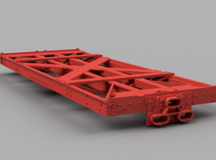
All D&RGW idlers I have ever seen, including at the Museum in Golden, have those cast triple pockets and use the small triple shank couplers. My understanding is two men could move them. Or, as seen in photos they could be used in pairs, or as you suggest, a single in the SG position on the rear. Being a narrow gauge Idler, you'd have to mount the triple pocket upside down. This is a Shapeways print that came up in a search for D&RGW Idler. This pocket would use a standard short shank coupler like one on a locomotive pilot. Even though the third rail is only on one side, if the locomotive and idler are turned, as they might often be, you still need the third pocket.
|
|
In reply to this post by Keith Hayes
Thr new print has arrived!!
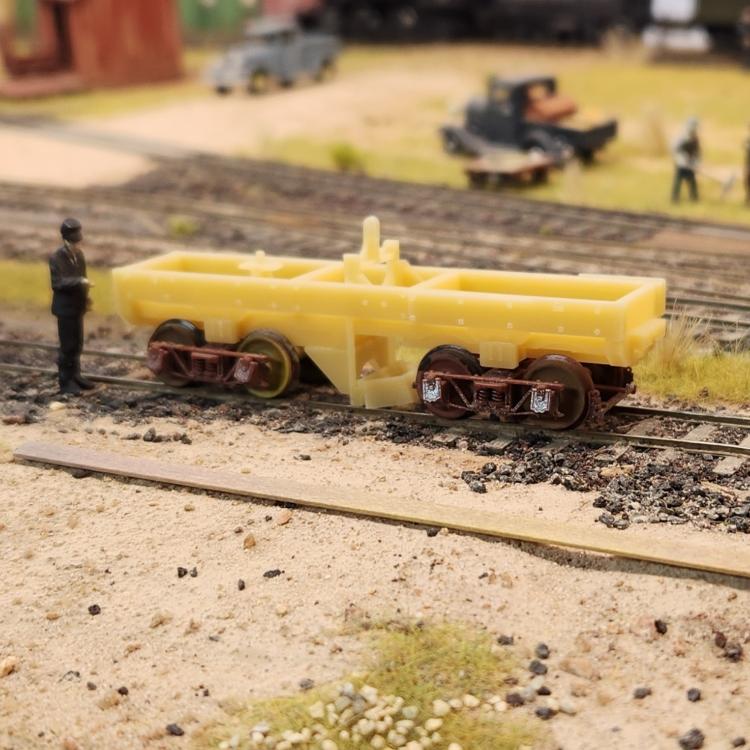 As Mike surmised, the blade is in the lower position. Also the wheelsets are a tight fit. All the nuts rendered, though and the metal castings look great! 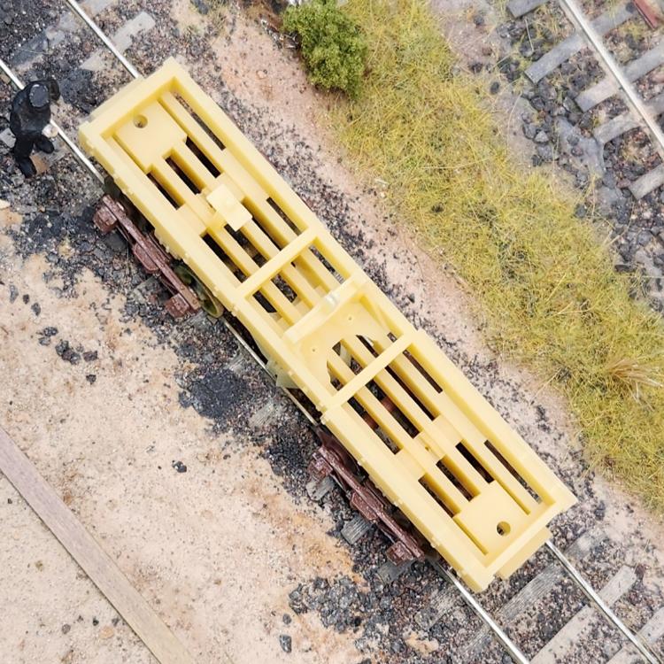 (image deliberately at an angle). Now I have to remember all my decisions from a couple weeks ago as I set to finishing this up! 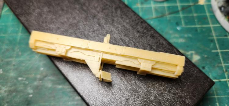 When I find someone time, I will raise the blade up on the print and post on Shapeways in S and O. Please stand by.
Keith Hayes
Leadville in Sn3 |
|
Administrator
|
Awesome! I'm amazed by all this. It's very interesting to see this in 3D with the lift present under the frame. Now you see the quandary of how to place one or two reservoirs and a brake cylinder in there. The RGS 01 had a longer body probably to accommodate that stuff. This why I placed the reservoirs sideways forward of the mechanical well. They could have been covered with decking and invisible. The brake cylinder is between the center sills forward of the rear truck.
On both 015 and 016, I had to carve out the flangeways for the wheels deep enough to accommodate a #6 frog. Our model flanges are oversized and this must be allowed for, as you say, the trucks are a tight fit. Ah, yes. Those decisions! Many of yours had to be addressed much earlier in this process. I will reach out to Keith Wiseman to see if he may have any O Scale hardware left over from his RGS 01 run. I don't know if he reran the HOn3 version and I'm sure it wasn't done in Sn3. Keep us posted, Keith. You are really doing great work. |
|
Progress.
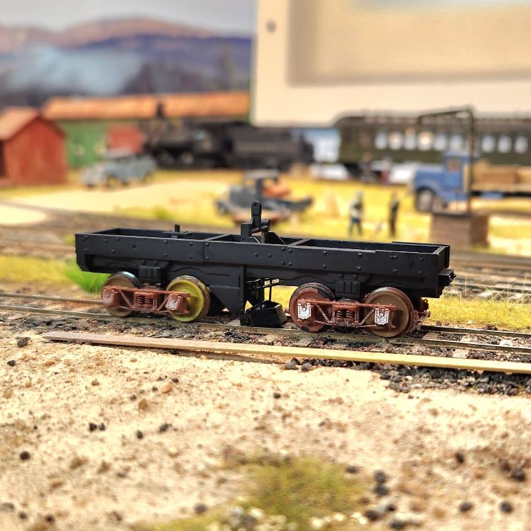
Keith Hayes
Leadville in Sn3 |
|
Progress on idler car 13. This is becoming a test bed for the flanger.
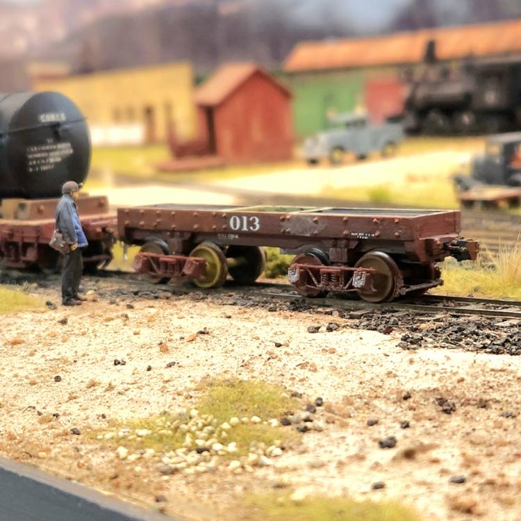
Keith Hayes
Leadville in Sn3 |
«
Return to C&Sng Discussion Forum
|
1 view|%1 views
| Free forum by Nabble | Edit this page |

