Flanger 015
12345
... 7


12345
... 7
|
Here are a couple of drawings provided to me by Jerry Day, D&RG early wood frame flanger drawings. He also mentioned the D&RG built the flangers for the C&S. These images aren't great, but I don't know how to add images to the file section, otherwise I'd put better drawings there. Any help?
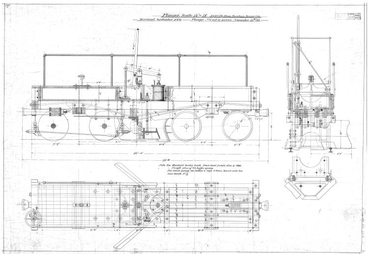 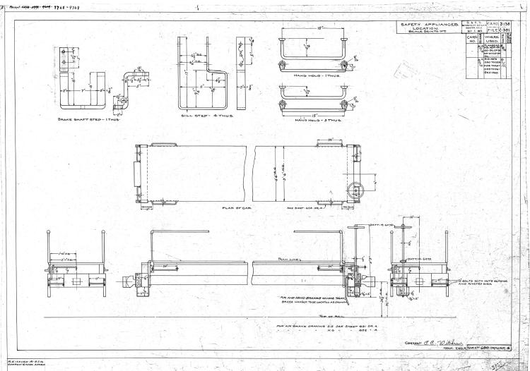 Hopefully they add to the conversation. Mike |
Re: Flanger 015 (and a little scenery)
|
In reply to this post by Mike Trent
Thanks Mike,
Great! I have a couple of those in my trucks and couplers box, so I'm all set. My good buddy the amazing Jimmy Booth was here for a week to help us run 20 and 491 and left more amazing scenery in his wake, as usual - it turned out really well. The loop that I use to get from Waterton up to South Platte on the upper level has been track, bare wood and foam risers for about 6 years, but no more! The actual photo I've included from about a mile and a half up Waterton Canyon near my house is what we used as a reference. I'll post better pictures when I get the mess cleaned up and some dirt and ballast put in. And the river. And trees. And literally hundreds of scenic tufts up above and scrub oak brambles down near the water... I also need to tweak on my lighting to diffuse it more. As always - a work in progress!! I look forward to coming up there soon, I'll contact you by email and we can plan it. Cheers, Norm 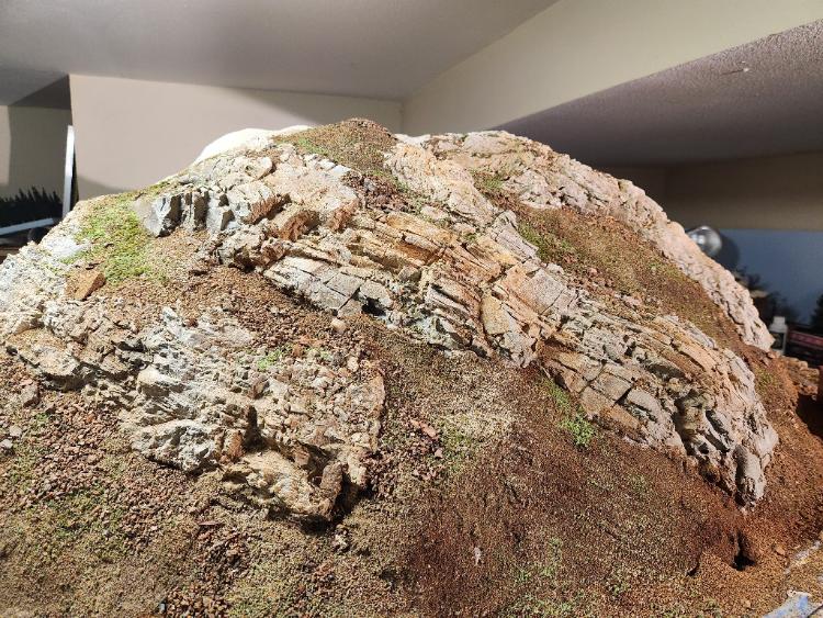 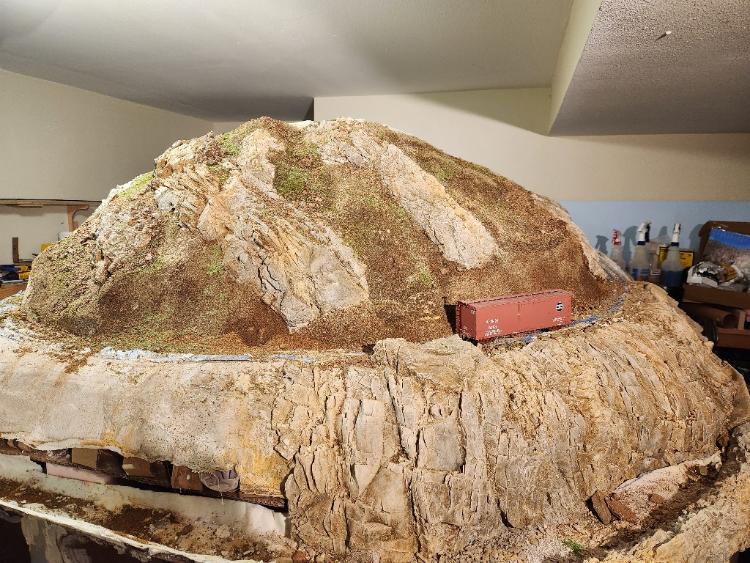  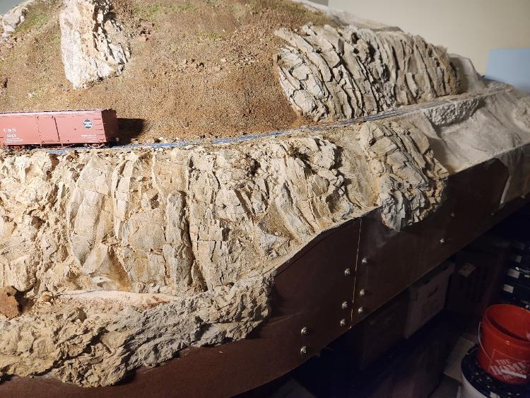 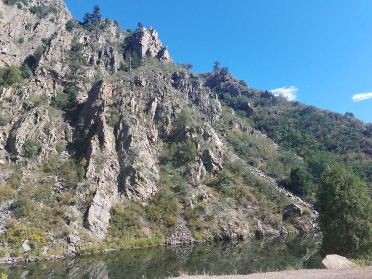
Norm in Littleton, CO
- on the C&S Silica Branch |
|
Administrator
|
In reply to this post by Mike McKenzie
Thanks, Mike. That does look a lot like the C&S Flangers and RGS #01. The frame and mechanism looks just the same. Maybe that will help Keith draw it. I think this frame is a little longer than the C&S Folio, but it's much closer than the newer appearance of the D&RGW Flangers.
I'd never heard the D&RG built these things, but that drawing sure looks like they have the same lineage. Thanks again. |
Re: Flanger 015 (and a little scenery)
|
In reply to this post by Norm Acker
That's some pretty slick rockwork, Mr Booth.

UpSideDownC
in New Zealand |
|
In reply to this post by Mike McKenzie
Hey Mike,
When I sent the folio drawings and standard plans to Darel for the "files", I made high resolution pdfs and attached them to an email to Darel. Or perhaps Mike could add them to the files section.
Jim Courtney
Poulsbo, WA |
|
Great scenery Norm, looking forward to more!
Have sent an email to Mike T. with high res pdfs of the flanger drawings to place in the files section. Mike |
|
In reply to this post by Mike McKenzie
Hi, Mike. Earlier in this thread I mentioned the UP journal's reference to the 4 South Park flangers, two in 1883 and two in 1887, built by the UP shops in those years at Omaha for the South Park. It seems there's little reason to believe that they didn't survive the 15 years into C&S days, inherited from the DL&G. But...there's always the possibility all were lost at some point and replaced. Or the technology is similar enough to appear similar between the roads? I'd be very interested in Jerry's source for the D&RG building the flangers that ran on the C&S, to add to what we know of the line's flangers--or to add mystery to the story. Do you know what he's basing that statement on?
Dave Eggleston
Seattle, WA |
|
Administrator
|
I'm as interested in the identical mechanism between the RGS, D&RG and DL&G flangers, as well as the frames and possibly the original trucks. I'm sure the mechanisms were patented commercial parts from somewhere. The frames could be fabricated by the carpenter shop. Maybe we can learn more. I know Jerry. I could reach out to him but there are others who know him better than I do. If no one replies about this I'll take a whack at it.
|
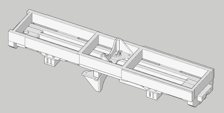 Thanks to Mike providing Jerry's flanger drawings, we now have some good detail on the lift mechanism. I spent a few hours today noodling over the drawings and I think I have the upper and lower brackets figured out. Previously I was missing a 6" x 8" lateral beam at the center of the car. The lower bracket mounts on the beam; the upper bracket is ahead of it about 3" and the lift rails for the flanger move between the two. The photo of the idler car has what appear to be a couple of truss rods. Studying the drawings, there is indeed a truss rod that extends from coupler pocket to coupler pocket, and there are two more rods that extend from the front beam back to the lower bracket as a brace. I already have a print coming my way of the first iteration of the frame without the brackets. I initially included holes for all the bolts in the side sills, but when I drew it the second time, I elected to eliminate them. But the Phase I coal frame turned out so nice, I will add them back to the model. I continue to be impressed by everyone's interest in the project. Thanks to you all for all the plans and photos!
Keith Hayes
Leadville in Sn3 |
|
The first test print is in!
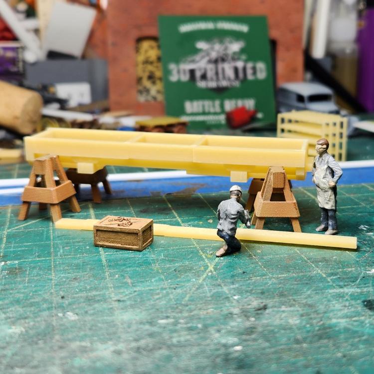 The new tan resin is impressive. I have 1" diameter holes and offsets of as little as 1/2" in S scale that printed! This sample is destined to become 013, as I sent it off before Mike provided me the 1885 drawing from Jerry Day. As you can see in an earlier post, I have added the upper and lower castings. With these results, I may also draw the various NBWs, having more confidence they will print.
Keith Hayes
Leadville in Sn3 |
|
Administrator
|
Nice job, Keith! I wish I'd had that drawing when I built mine years ago. I see the truss rods you mention which on 015 support the Crossbeam at the blade.
I found the large drawings email in my junk folder but they failed to download completely and I can't open them. I'll ask Mike to resend them separately. You may already have the most complicated parts of the mechanisms identified The side levers which are on the ends of the large handle are visible in the drawing. There is a rotary stand that extends out of the large steel base similar to a switch stand. You and I have already discussed that in later years, the C&S for some reason disabled the mechanism so that the blade is rigidly fixed in the raised position at the same time the handle lever is in the lowered position. Obviously, they must have felt the priest flangers on the locomotive's pilot truck was sufficient to clear the flange ways. With the flanger blade fixed in the raised position there would be no reason to raise the blade for grade crossings. |
|
Gents,
Indulge me in a little non-modeling tech talk on the flanger subject. Being one of those fools forced to understand the physics of snow, and removal of same, these little cars appear to this observer to be hard to keep on the rails, in a weight/wheel flange grip vs. side force placed against the car by an assymetric snow load. Were the blades strategically leaned back enough to undercut the snow/ice/load, thereby automatically creating a downward force that kept the flanges from being pushed over the rails when dealing with assymetric side pressure ?
"Duty above all else except Honor"
|
|
In reply to this post by Mike Trent
Just got this from Jerry...
"Mike, the D&RG flanger was designed by the Leadville shop manager, a man named Omerod. The D&RG patented the mechanism design. The D&RG built flangers for the Rio Grande Western, the Silverton RR, the South Park, and the RGS. The RGW flangers were sold to the RGS and Silverton Northern when the RGW was standard gauged. The D&RG standard gauge flangers were essentially the same design, just modified for the wider gauge. Some operational tidbits… Leadville Herald Democrat November 23, 1886 Both the D&RG and South Park have got their patent flangers ready for winter operations and all snow will be thrown as far as possible as soon as it falls. Evening Chronicle, Leadville January 29, 1891 Gossip from the Rails Flangers in Use The flangers on the Midland, Rio Grande, and South Park were all ordered out yesterday. On the Grande it went over the Blue River branch to Dillon, where quite a quantity of snow has fallen. Leadville Daily & Evening Chronicle November 17, 1892 Gossip From The Grade The South Park and Rio Grande yards had not drifted to any great extent up to 6 o’clock yesterday evening. The flangers on both roads were out all day and managed to keep the tracks clear at all drifting points. A flanger was also at work on the Blue River branch, and kept the road clear, so that all trains moved on time. Jerry B. Day" Hope this helps. Mike |
|
Administrator
|
In reply to this post by South Park
Yes, SP, you have described it pretty well. In addition to snow and ice management, these flangers were also used to spread ballast and cinders. They had a hard life. It's easy to see why #015 was the only remaining flanger after 1930. The D&RGW rebuilt their flangers over the years as to be almost unrecognizable from the appearance in these drawings.
|
|
Administrator
|
In reply to this post by Mike McKenzie
Thanks, Mike. This is fascinating information. Jerry keeps his sources close to the vest, but perhaps he has more in his book on snow fighting equipment. Which I think has been published.
Thanks so much for sharing these drawings with the group. I'll see if I can add them to the blog archives, properly attributed to you and Jerry. |
|
In reply to this post by Mike McKenzie
Mike, thanks for the information from Jerry.
I'm most interested in the Leadville Democratic Herald of 1886 which specifically mentions the patent and suggests a connection of it to the South Park flangers. These flangers were built in 1883, two years before the D&RG tested Omerod's patent so I'd argure these first two cars were UP-built and upgraded later with the newer D&RG patent mechanism. The South Park Journal doesn't give a builder for the two 1887 flangers. Did the UP supply the frame, ironwork and trucks and use the D&RG patent for the flanger mechanism on these two cars or did they simply buy full flangers from the D&RG? Or were these fully built by the UP to some other design and later adapted with the D&RG mechanism? My gut inclination is the first two cars were UP-built and modified later while the second two were UP-built frames/hardware/trucks and possibly used the D&RG flanger mechanism. But I bet I'm missing something--Jerry might be keeping things close to the vest as Mike Trent suggests!
Dave Eggleston
Seattle, WA |
|
In reply to this post by South Park
Espee, you are correct on all points.
The issue I have been struggling with is the flanger mechanism. All the photos seem to hide a key part, but Jerry's drawing is a huge help. I have marked it up in the hopes to demystify the works. 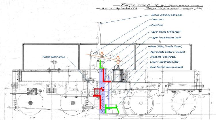 The fixed parts are in red, the moving parts are green and the purple are the alignment rods and (for lack of a better phrase) "trestle" the blade moves up and down on. As Mike and I corresponded behind the scenes, I figured that flangers had to have some sort of truss rod to hold the works together, and indeed they do! There is a needle beam just aft of the center of the car. Two truss rods run from the coupler pockets under the needle beam to lock the car together. Further, there are two more rods that extend from the draft gear to the lower fixed bracket to help resist the rearward force the blade places on this bracket when plowing. In structures, we call this a rotational moment: in the diagram, the force of plowing induces a clockwise motion on the lower bracket. This force is resisted by the two rods, the needle beam and the frame of the car. The blade also places a force on the trestle, which in turn bears on the rear-facing face of the upper fixed bracket. Using high-order computation (my eyeballs), the center of the moment seems like it is about at the bottom of the beam. This in turn induces a force on the top of the car sills and downward on the front truck. The air cylinder moves the live end of the lever up to raise (and lower) the blade. There is also a manual handle and the sides are in the form of a cam to provide a touch of leverage in the case Jumbo was not assigned to the crew. The manual lever can me secured in the raised position with the bracket above the rear truck. 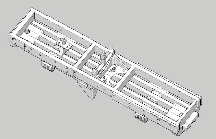 I recall reading that Al Pearlman directed D&RGW NG maintenance crews to stop using rail-based MOW equipment like flangers and spreaders. Caterpillar tractors created much more wear on the track and were less efficient. I heard when Spreader OU was resuscitated about a decade back, the crews really enjoyed working with it because all the forces...just worked. The car was heavy (OU is all-steel), the blades are symmetric about the track center line, and it was designed to move snow and rock. The C&TS crews were able to get a lot of work done in a short period of time, and I remember the ROW profile looked amazing! I suspect flangers are similar to operate as OU. Jerry Day's video of the D&S flangers make it look pretty easy. The axial loads extend through the drawbars, and the center of the moment seems reasonably low. You can bet that they could be fussy, though as all the forces are kept on the tracks by the weight and some pretty small flanges. These cars weigh 22,000 pounds wet--the space under the platform and between the upper beams was packed with scrap. I will put in a couple brass bars and leave a board off to show some tie plates, spikes and fishplates. As the photos indicate, mishaps were common, and the D&RGW learned from this and rebuilt them with steel frames. The truss rods seemed to remain in place, but they just got welded to the steel and don't seem to extend to the draft gear plates at the car ends--at least on OC.  Progress on the revised frame is purring along. I have one last piece to model, the blade bracket. I will create this as a separate part, and fabricate the blades out of brass and styrene. It just seems easier that way. As the first print turned out pretty well, I modeled most of the square carriage bolt nuts, so now I don't have to drill those out. Same for some of the bolster end detail, and some nice metal straps. The air piping, handrails and signal mechanism will all be fabricated from brass. If the car works out in S, I will post it on Shapeways in S and O for others to purchase. I am not going to guarantee this is the most accurate model, but it may be faster than doing it yourself if you just have to have one of these. Sound like the origin story is still up for debate. The D&RG, RGS and C&S cars bear remarkable similarities, though photos of key parts are limited. Even if they are not the same, they are pretty close, with the exception of RGS 01 having a much longer frame with the blade set forward on the car. I will let a physics specialist school us on the forces, but that doesn't seem like the right move, unless they had a large load on the rear truck. In S, this is a tiny little model, about 3" long.
Keith Hayes
Leadville in Sn3 |
|
Nabble doesn't like file names that are too similar. Here is the view of the underside of the flanger model.

Keith Hayes
Leadville in Sn3 |
|
Administrator
|
Looks great, Keith. Really great.
Dave, it's anybodys guess, but we've sure learned a lot through the course of this thread. I'd like to encapsulate this information in the Blog. It sure belongs there. |
|
In reply to this post by Keith Hayes
Here is the final model. I am uploading it now.
 More as I know it.
Keith Hayes
Leadville in Sn3 |
«
Return to C&Sng Discussion Forum
|
1 view|%1 views
| Free forum by Nabble | Edit this page |

