Early #22 In Progress
12
12
|
Administrator
|
I have posted pictures of this engine previously, and I'm not sure if there is much progress since then to now.
There has been some interesting discussion about the B-3-B class recently and how these engines were rebuilt by the UP in the 1890's. This engine is a collaborative project between Rob Smith and myself, and it has been stalled far too long, and the time has come to get things going again. This engine started out as a PFM/United "C&S 2-6-0", and dates back to the early 60's. I found it on ebay several years ago, after havind completed my early vintage #7, and Rob and I thought this would be a great companion model to it. I cut off the smokebox extension, removed the single air tank from the top of the boiler, and we cobbled up a McConnell stack for it using the top of a resin cast one Rob had, same as I did for #7, and a PSC banded straight stack from PSC, cut off to the correct length under the diamond. Made up a new modified PSC based headlight, an old style pilot, added the large air tanks for the rear, remounted the bell, and what you see here is the result so far. United did a really nice job on this model, and several of the castings that were used became "standard" fare for future C&S projects and conversions from the Back Shop. Later, I will post photos of this engine with #7, and you will find the comparisons quite interesting. Both are very close to the respective prototypes. At first glance similar, at second glance quite different. I've had a request for some detail shots and some measurements of the peculiar locker boxes, which are quite different from anything else I am familiar with. So, first, three overviews: 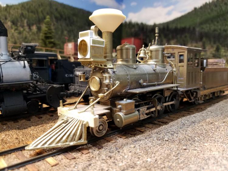 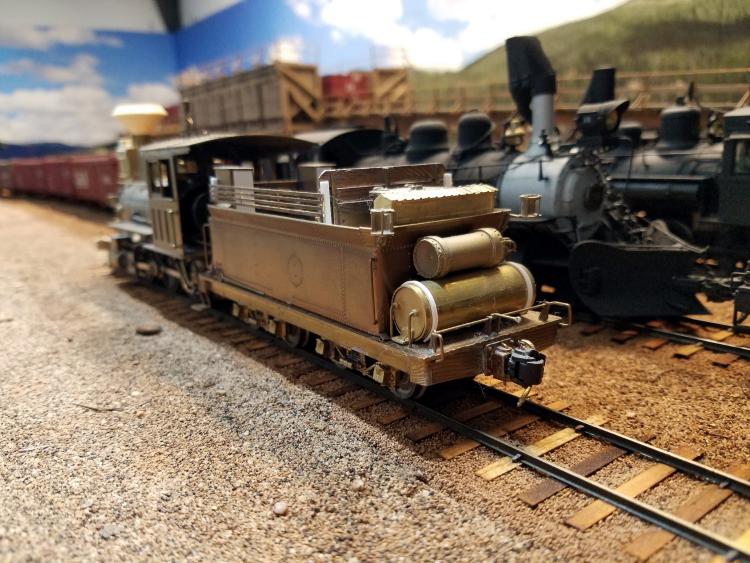 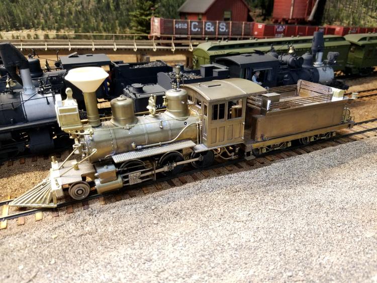 More to follow shortly... |
|
Administrator
|
Now, some detail shots of the tender locker boxes:
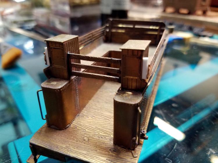 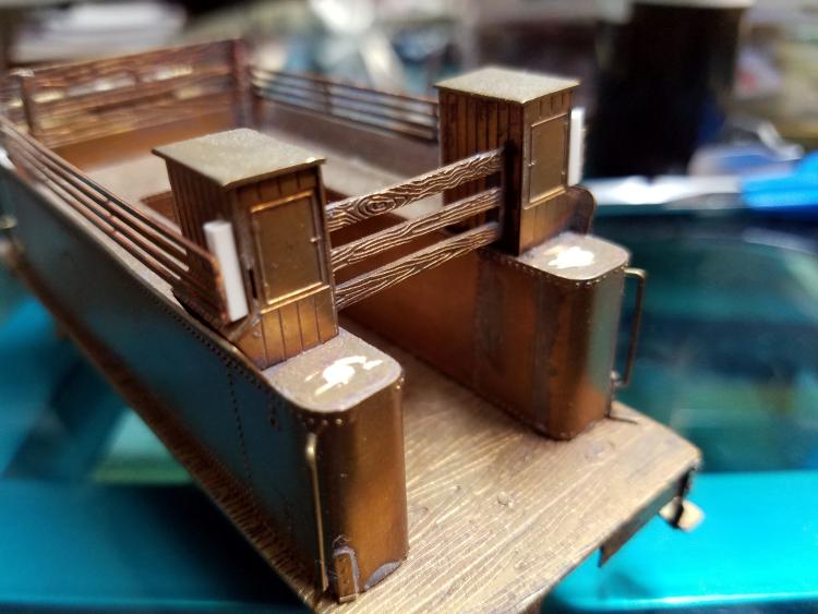 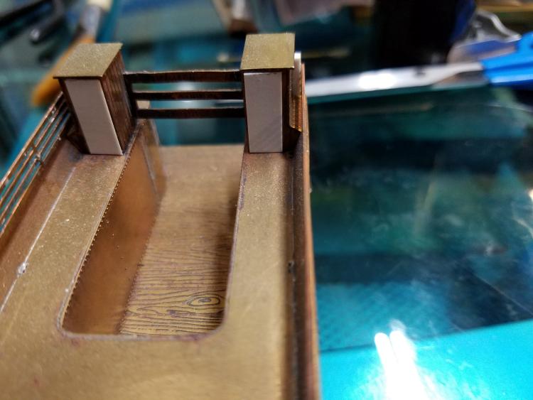 As you can see, there is an angled base attachment which mates to the flaired sides. What we see in these pictures sure looks like what I see in photos of #22's boxes. Wood sheathed, quite tall, and not large. I did not make #7's boxes like this. Instead, #7 had steel boxes, and I don't believe they were bolted to the flairs like these are, but it would have made sense if they were. The boxes make up an integral part of South Park tenders. They form the structure which secures the upper coal gate, and they offer at least some protection from the weather. They also secure the upper side sheets of the bunker, whether they are sheet iron, wood, or open slats like #22. The tops of the boxes measure 15" wide X 24" long. They are 30" tall to the underside of the tops. The width of the upper part of the boxes are 14", and they are 28" deep. So there is a little overlap for the top. The width of the base at it's widest part where it follows the flair is 18". The distance from the top of the water leg to the bottom of the small door looks like 10". The door itself is 10"X15". The sheathing is 3", like freight car sheathing. I used 4X4 styrene to secure the slats to the boxes. I think this has to be pretty close, but I can't say they aren't off a bit. looks good to my old eyes. Let me know if you need anything else. |
|
In reply to this post by Mike Trent
Mike: thanks for the pictures and measurement. I will contact my On30 friend about this. He's an outstanding modeler whose locomotives are excellently do. His name is Les Davis. He loves to build unusual engines and has a 3-d printer. Again thanks Mike.
Fred Cotterell. Southern Alabama
Ohio Creek Extension
|
|
In reply to this post by Mike Trent
Beautiful model building as always, Mike.
I've been scheming to back date an Sn3 Overland #21 to a circa 1901 version of C&S 22 (previously DL&G 162):  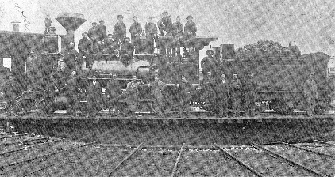 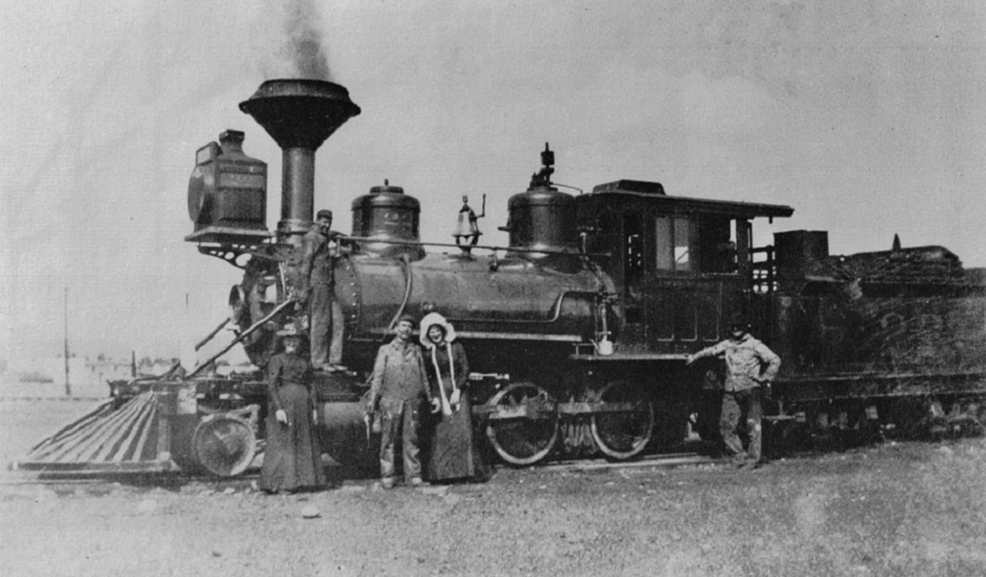 All three images from Kindig, et al., The Pictorial Supplement . . . The original Brookes locomotives had new frames built in the 1890s, the equal driver spacing on the original Brookes 2-6-0's being changed to match that of the unequal driver spacing of the original Cooke locomotives. If the DL&G predecessors of C&S 21 and 22 were rebuilt by the UP in the late 1890s, to match the Cooke 2-6-0 predecessors of the C&S 11, 12 and 13 that were rebuilt at about the same time, it would mean that the newly formed C&S of 1899 inherited a class of five 2-6-0's which were similar in appearance but differed slightly in specifications. The newly created C&S, rather than continue the UP project of rebuilding the remaining Cooke 2-6-0s (C&S 4-10), decided to up the ante and rebuild the Cookes into much larger and powerful locomotives. Ironically, the rebuilt Cookes 4-10 of 1901 had new frames constructed, with an equal driver spacing roughly matching that of the original Brookes 2-6-0s prior to the 1890s rebuilding. Does this make sense or do I need to re-write it?  As a comparison, consider these photos of early C&S Cooke 2-6-0's numbers 5 and 8: 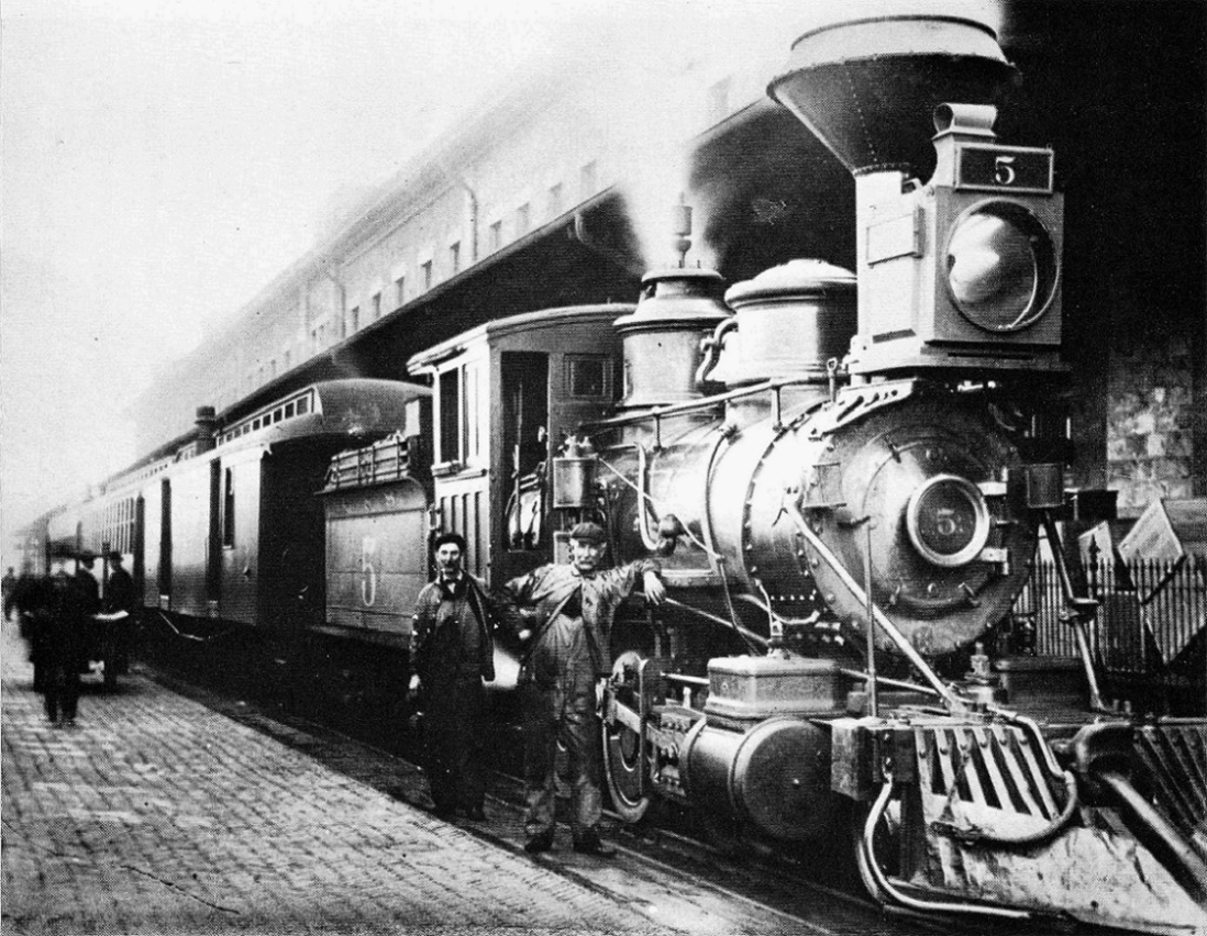 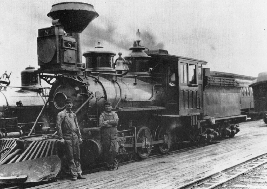
Both images from Grandt's Narrow Gauge Pictorial VI C&S 5 was rebuilt in August, 1901 and C&S 8 was rebuilt 2 months earlier, in August of 1901. Prior to rebuilding, 4-10 still had their original Cooke ringed domes, unlike the rounded top domes on the UP rebuilds of 10, 11, 12, 21 and 22. Otherwise, they were very similar critters in most dimensions and details. After rebuilding, C&S 8 looked like this about 1903: 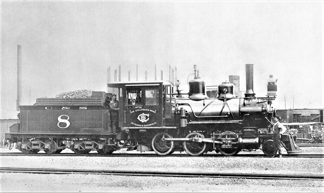 Image from Kindig, et al., The Pictorial Supplement . . . Since the Overland Sn3 C&S 21 model has the same driver wheel base as the original Cooke drivers, I have a second number 21 that I'd like to backdate to either C&S Cooke number 5 or number 8, as in the above photos -- haven't decided which as yet. I suspect I'm going to get a lot of ideas for construction from Mike's beautiful On3 backdates . . .
Jim Courtney
Poulsbo, WA |
|
Jim: As usual excellent information. I will use some of the details of #8 if i ever get around to building one.
Fred cotterell
Ohio Creek Extension
|
|
In reply to this post by Jim Courtney
Having re-read my own post, a couple of questions come to mind:
Why do ya'll think that the injectors on C&S 21 and 22 were place in front of the cab, on both sides, the steam pipe originating from valves directly on the steam dome, while the Cooke rebuilds had the injectors in the cab, with steam lines coming off a turret from a pipe running back from the steam dome through the cab front? This detail seems to vary on the C&S Cooke rebuilds of 1901 as well -- the engineer's side injector on several engines (like that on number 8) was placed in front of the cab, while the fireman's side injector was usually inside the cab. Two of the lower numbered Cooke's, number 7 and number 9, acquired round topped domes (those on 9 more "roundy" than on number 7) prior to 1901. Is it possible that these two locomotives were shopped/rebuilt by the UP in the 1890s as well, along with 11, 12 and 13? If so, these two locomotives were rebuilt twice, in less than a decade? Anyone know of records that might prove or disprove this thought?
Jim Courtney
Poulsbo, WA |
|
Administrator
|
This post was updated on .
Hi Jim,
First, thanks for your comments. Yes, the Cookes were "upgraded" by the UP in the 1890's, and also in the 1880's. The first major upgrade was the replacement of the cylinders and the original "Laird" single guide. New, larger cylinders with "alligator" style crosshead guides must have increased tractive effort and efficiency. They sure modernized the appearance. For #7, I scavenged new cylinders, guides, and even the main rods from an over-run OMI Mogul frame that I bought on eBay from Bill Davis. As you note, in the 1890's, #7 also received a new rounded sand dome and matching steam dome cover. For these, I used PSC rounded C-16 domes, which appear to be virtually identical. By contrast, #8's domes were not replaced, as your photos show the original Cooke domes. Also, the tender trucks were replaced with what we would recognize as "C&S" style trucks in the 1890's, just as the Brooks and Cooke UP rebuilds received also in the 1890s. I found an excellent side view of #7 in D&LG days virtually identical to #7 in the famous photo at Como in 1899. One of the things to note on the UP Brooks and Cooke rebuilds of the 1890s is how much higher the original Cooke boilers sit on the frame. The new UP boilers such as on #22 sit about 6" lower to the frame. To compensate for this in the rebuilds, the domes and the cabs were replaced to raise the height to match the Cookes, like #7 and the others which eventually became B-3-C's. If you study the profile of the domes and cab profiles of these engines you will see this to be consistent between the two types of engines. #'s 11-13, 21, and 22 are UP rebuilds, #'s 4-10 before their rebuilds by the C&S starting in 1901 with the original Cooke boilers and cabs. You will note that your photo of #5 shows that it also had it's original Cook domes. You mentioned #9 had rounded domes, I believe #6 did too. Not sure about the others. #6 carried a straight shotgun stack and had an extended smokebox prior to its rebuild. So the UP did a lot of tinkering and experimenting on those Cookes before they were rebuilt. Another of the early pre-C&S UP upgrades were the UP Style smokebox fronts. I used an OMI #22 front for #7, also acquired from Bill Davis on ebay. Not a coincidence that the diameter matched! |
|
In reply to this post by Jim Courtney
The round domes on the #9 have always seemed to me to match those in photos of the Baldwin 2-8-0 class B4Ds #63 to #70. I usually think of the rounded domes as "Baldwin" domes. Also, photos of the #67 show her with the unique look produced by her Baldwin steam dome nring replaced by one of the flattened Brooks/Cooke steam domes. (See Corman's Narrow gauge Pictorial vol VI pages 160 -161 for example.) I have always wondered if during some maintenance work, the early #9 and #67 swapped their domes for some reason. The swapping story may be more complex as at least two of the B4B 2-8-0s, #37 and #39, also got their flanged domes replaced with the rounded Baldwin domes sometime around 1899-1900. Early photos of the original B4B flanged domes seem to show a flatter top, so the round domes weren't just the originals with the trim rings removed. I like to think that the #67 got the #9's original steam dome at least. I wonder of the UP shops had a source of replacement Baldwin domes that migrated onto the #9, #37, and #39. If only that boxcar full of maintenance records hadn't been destroyed... Skip Egdorf Los Alamos, NM
Skip Egdorf
|
|
In reply to this post by Mike Trent
What about some backdated short smoke box Rhode Island,Baldwin,and UPD&G Baldwin Consolidations?When did the Rhode Island engines lose their as-built extended smokeboxes?The was an article or articles in SlimGaugeNews discussing the Mogul rebuilds.
|
|
In reply to this post by Jim Courtney
I don't recall the photo of 22 with the 2 ladies in it being in DSP&P Pictorial.
|
|
This thread is sooo good. Especially since the now where the layout lumber is here.
With my two locos i have will be a little more detailed than i had planned. If anyone knows of a Bachmann Mogul without the air tank on the boiler I'd like to know. Also, did #21 ever have a Ridgway arrestor? Or just that cone? And for good measure, did both locos have air tanks on the rear of the tender? I noticed that there were on one photo on the thread. Its just these details I want to incorporate. I know that these engines in On30 are not exactly prototype but its what i can afford Fred Cotterell Southern Alabama
Ohio Creek Extension
|
|
Administrator
|
This post was updated on .
Hi Fred, Yes, #21 did have a Ridgway spark arrestor. It was scrapped in 1923, all narrow gauge engines on the C&S had them after 1918.
Air tank..... Yeah they both did, I'm sure. A small tank above a toolbox that you can see in the pictures. If you look carefully of pictures of the engineer's side a the rear of the tender tank, you can see an air pipe in pictures I've seen, but not the tank. This would be similar to the 12" diameter air tanks you see in later C&S locomotives, and are just what those were. Air for the engine and tender brakes. Remember that large platform held the large tanks before the large one was replaced by the tank on top of the boiler, but the smaller tank would have been mounted just below the tender flair. Here is a rough quick pic out of the "Narrow Gauge Pictorial Volume VI" 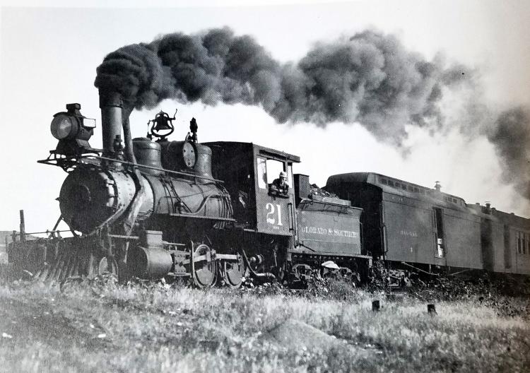
|
|
In reply to this post by Fred52
Also, did #21 ever have a Ridgway arrestor?
http://digital.denverlibrary.org/cdm/fullbrowser/collection/p15330coll22/id/42509/rv/singleitem/rec/11 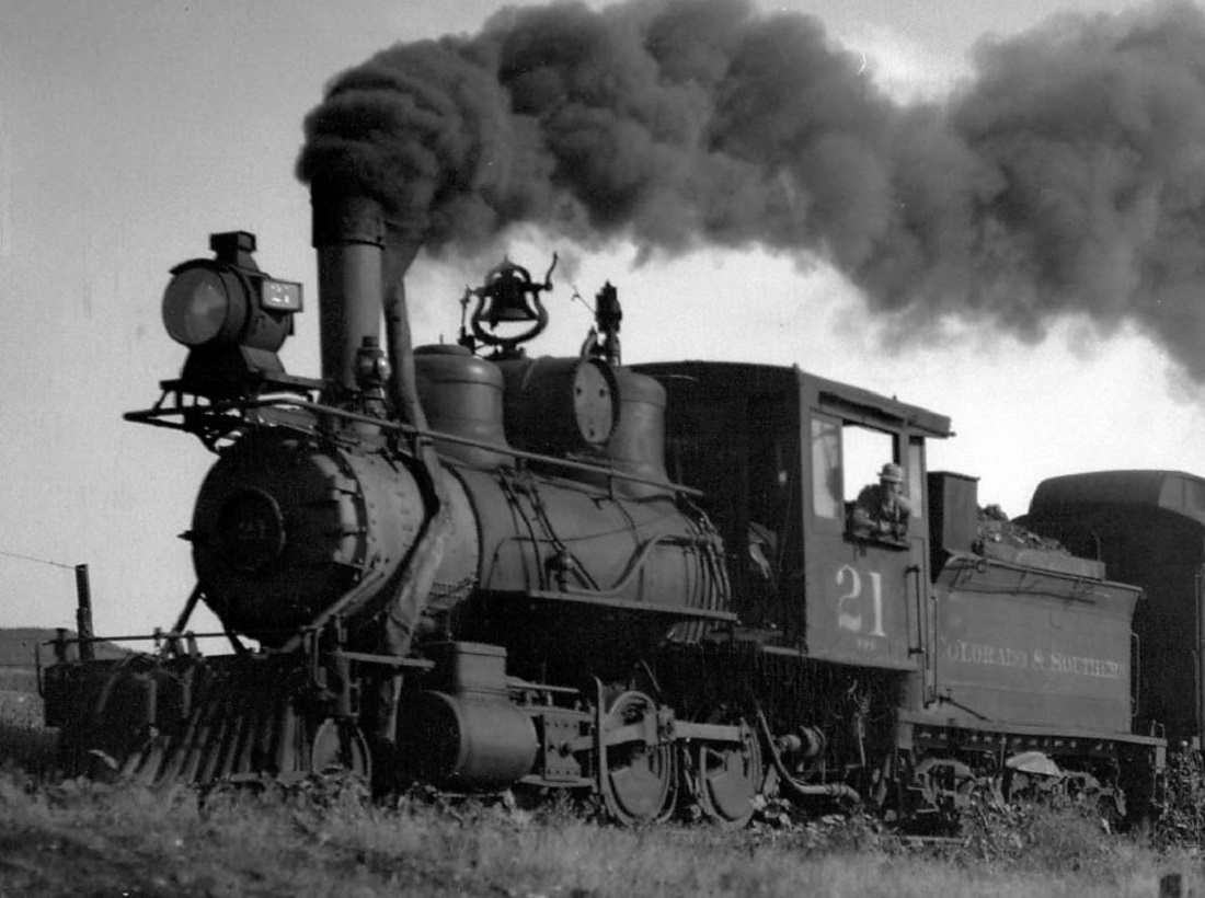 Otto Perry photo, 1918 And for good measure, did both locos have air tanks on the rear of the tender? Not at the same time, the original air tank was on the rear of the tender, removed when the air tank was mounted atop the boiler, about 1903. Mike and I seem in sync within 4 minutes! 
Jim Courtney
Poulsbo, WA |
|
Administrator
|
Hi Jim, I never noticed this before I saw it in the picture you posted. That is the wimpiest, most battered looking cinder tube I've ever seen. A disgrace. Looks like it was made for a movie prop. Hope Keith sees this.
|
|
Yeah Mike,
One wonders if this isn't one of the first applications of the new Ridgeway stack, kind like the shops hadn't worked all the kinks out yet. Don't you think that the spark arrestor itself sits higher on the straight stack than in later years?
Jim Courtney
Poulsbo, WA |
|
In reply to this post by Mike Trent
What a cinder tube!
Is it possible that this locomotive was in storage, or that the tube was damaged in a rollover, or...perhaps cannibalize from a loco that had a rollover? Studying the smoke plume, the hinged portion of the arrestor is not visible. Is it flipped over, or is this another clue that the arrestor was removed from a damaged loco for use on the 21? How in blazes do you know that the domes on 59 were removed and used on a CB&Q park engine? I sure wish Mr. Poole would wander by and enlighten us on the sequence and dates of C&S loco modernization.
Keith Hayes
Leadville in Sn3 |
|
Administrator
|
Yeah, you'll also note that it actually does "corkscrew" the way some importers have characterized it on models. To which everybody scoffed.
For sure this would have had to have been one of, if not the first, to have been fitted with the new Ridgways. My guess is that it was made of much lighter gauge sheet iron, and got beat up like that bucking snow somewhere. Could even have been caught in a slide. I'm sure, as with anything else, it took a while to get all that stuff figured out. Interesting that in all the dozens or more times that we've all studied that photo, I've never heard of anyone noticing it. I'm more surprised by the cartoonlike corkscrewing (I think I read Harry Brunk describing poor import models like that) of the cinder tube than how thin the metal must have been. Wow. Learn something new every day.... The top is probably in the correct position, obscured by the dense smoke, and that thing does seem to sit pretty high on that stack. Lowering it could have made it possible to angle the tube the way we are accustomed to seeing them. Using heavier sheet iron would have made forming the tube with fewer bends a good idea. This really is an interesting picture that way. "Evolution". |
|
In reply to this post by Jim Courtney
When I was researching my B4A-B4B engines based on the Key #22 in HOn3 I did a bunch of stack measurements from photos. The easiest way I found without worrying about absolute inches was to use a dividers and compare stack diameter in a picture to its height, So some photo might show a stack height of say 3-1/2 stack diameters. All the diameters seem to be similar in the photos (no real basis, that is just how they look to me) but the #21 seemed to have about 1 to 1-1/2 diameters more height than the #12, #13, or #22 which all seemed to have the same ratios. Interestingly, the Key #22 in HOn3 has the stack height/diameter ratio of the taller #21 rather than the supposedly modeled #22. This is probably good as it is easier to cut off a bit for the #22 than to add a bit for the #21. For my #13, I cut about 1 scale foot off of the stack to lower the height to better match the photos I had. Skip Egdorf Los Alamos, NM
Skip Egdorf
|
|
This post was updated on .
Interesting stuff,
Looking at other C&S locomotive portraits taken by Otto Perry in 1918, the year that the Ridgeways seem to have first applied to the narrow gauge power, there does seem to be variation in height above the stack: http://digital.denverlibrary.org/cdm/singleitem/collection/p15330coll22/id/42095/rec/90 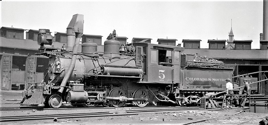 July, 1918 http://digital.denverlibrary.org/cdm/singleitem/collection/p15330coll22/id/42171/rec/25 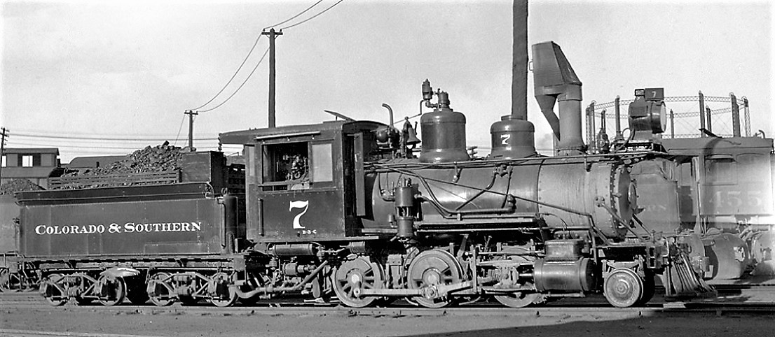 May, 1918 http://digital.denverlibrary.org/cdm/singleitem/collection/p15330coll22/id/42194/rec/56 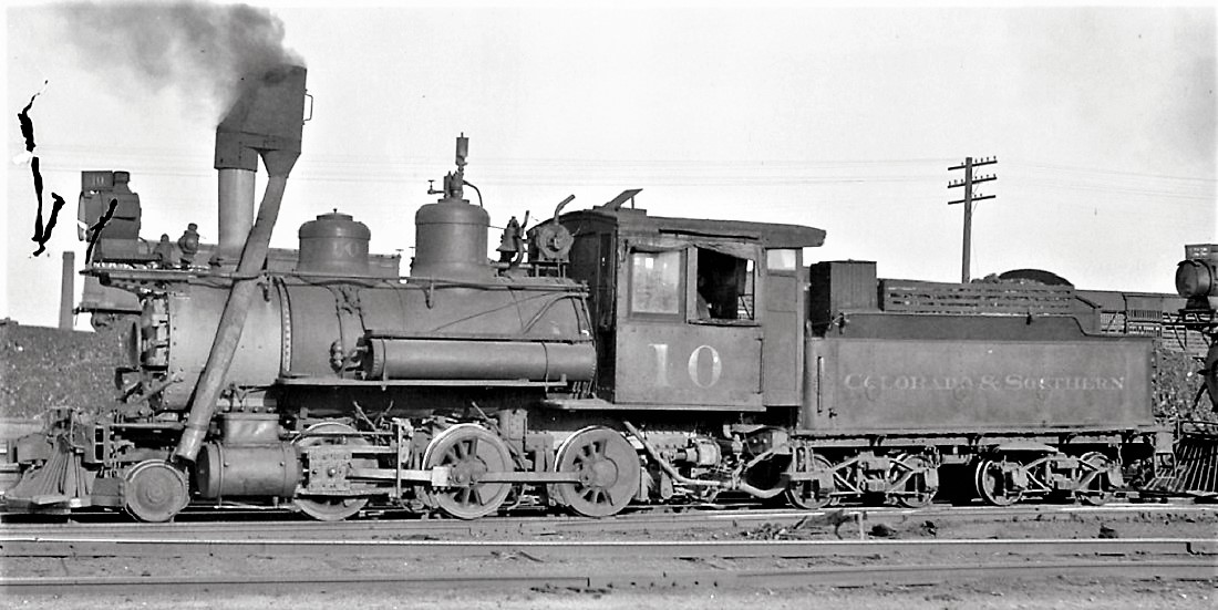 July, 1918 http://digital.denverlibrary.org/cdm/singleitem/collection/p15330coll22/id/42509/rec/20  July, 1918 http://digital.denverlibrary.org/cdm/singleitem/collection/p15330coll22/id/42202/rec/42 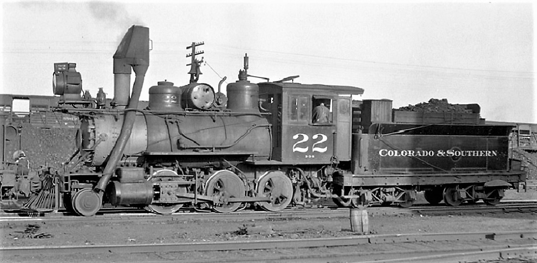 July, 1918. The Ridgeway atop number 5 seems squat, mounted lower on the stack than the other locomotives. The Ridgeway on number 10 seems much higher than the others, but not as high as number 21. Maybe standard applications of the device to all the narrow gauge locomotives was still a few years off.
Jim Courtney
Poulsbo, WA |
|
Administrator
|
In reply to this post by Keith Hayes
This just seems so unlike the C&S to run this ratty looking thing. Because of the way it lays so flat, I'm gonna go out on a limb here and say that maybe what we are looking at is not mangled sheet metal. But perhaps rather an experiment using a soft canvas like material.
 IDK IDK

|
«
Return to C&Sng Discussion Forum
|
1 view|%1 views
| Free forum by Nabble | Edit this page |

