CONX 14
123
123
|
In the never-ending quest for more tank cars, CONX 14 has long caught my eye. It is an odd duck, one of three tank cars (12, 13 and 14) constructed for Conoco by the D&RGW in 1919 using existing tanks. The cars are distinguished by the fabricated steel handrails angling up from the side sills the length of the tank on both sides. The three tanks are all different sizes, with 12 being the shortest, 13 being the longest and 14 being just right. There are one or two photos of CONX 14 in service on the South Park with white lettering on a black tank. I personally wonder if the car survived in service on the isolated Climax line into WWII.
Bob Stears kindly translated the folio into a nice drawing which was published in the Gazette in 2020. I used these to make some parts in Sketch Up. The frame has given me fits for some time, and finally today, I was able to successfully post the model to Shapeways. 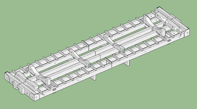 The part is bilaterally symmertrical, so I only needed to model one quarter of the frame and mirror it to obtain the entire car. If this doesn't work, candidly it will be faster to make the thing out of styrene. It would be shame, though, as I used Bob's drawings to provide dimples for the various parts and NBWs. I also have modeled the tank: 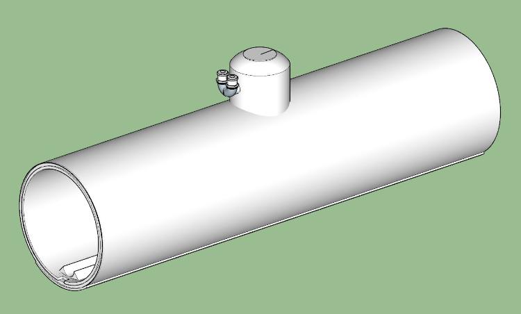 This part rendered more easily in spite of the complex shape. A grove is provided along the bottom for some added weight. Curiously, this car has a double vent, unlike just about any other car I have seen. The photo lacks detail of this part, as does the drawing, so I visited some examples at CRRM and started drawing: 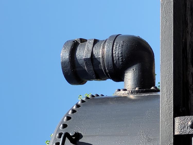 I also modeled the ends, which have a small index pin to align them properly in the tank. Stay tuned: the parts should arrive in a couple weeks and I will share an update on how they turned out. If all goes well, this will be my final car for the NMRA AP Cars certificate and I might post the parts on Shapeways for others to download.
Keith Hayes
Leadville in Sn3 |
|
Keith
Great project. Tank cars can be a challenge to print if you want to get a smooth and perfect form. Regarding the ends I have added an extension to the part so I can put them in a drill chuck or lathe. You'll be able to sand a smooth surface that way. 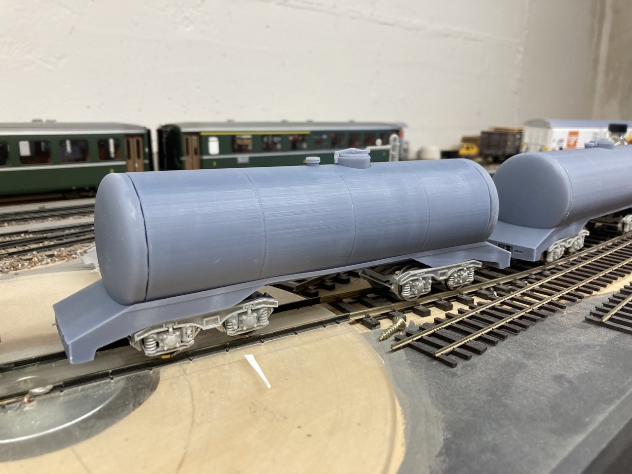 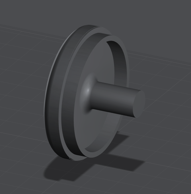 Finally I have found that there are different level of details that you can export a stl file in. Only larger files will give you a really round surface. Hope this will help. Christian |
|
In reply to this post by Keith Hayes
Keith
What you're calling vents are 6" safety valves. MCB Specifications for tank car require one 6 inch valve for every 6,000 gallons or fraction thereof. Pat |
|
In reply to this post by pizlinard72
Christian
There is a program, OpenScad, that is great for round objects and uses a variable, $fn, that dictates the smoothness. The other great thing is that OpenScad is free. Pat |
|
In reply to this post by Keith Hayes
Hey Keith,
The "Siamese twin" dome safety valves were known as twin L-mount valves. I found some nice HO brass castings for these guys at Owl Mountain Models https://www.owlmtmodels.com/detail_parts/detail_parts.html They are perhaps a bit undersized for S scale, but seem to look okay on smaller TOTC tank cars: 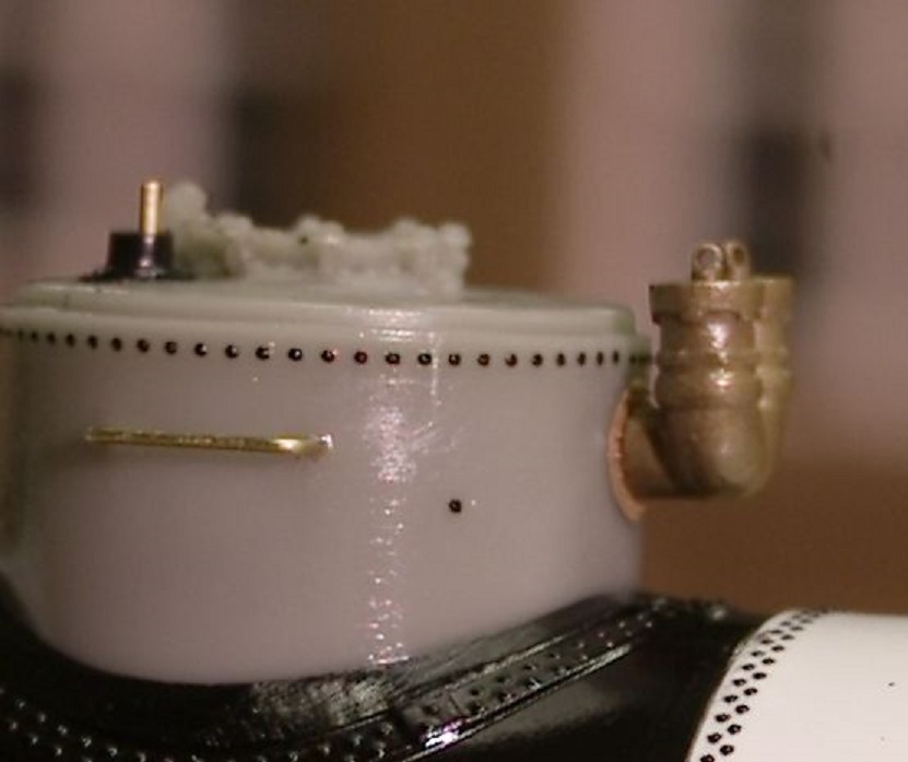 Unfortunately, they are currently out of stock. Info from Owl Mountain: "This vent model represents the Master Car Builders design from 1904 for a double (or "twin") "L-shaped" manifold 5" safety vent for tank cars over 8,000 US Gal. These vents were commonly seen on 8K, 10K, and 12.5K tank cars in general service. The distinctive manifold is easily picked out in photos. These vents had an L-shaped manifold connecting the vent to the expansion dome of the tank car part way up. They were used on all general service tank cars until about 1918 when the standard recommended design was changed to mounting the same 5" vent head on a flange in the top of the dome. This prevented the L-shape manifold from expelling the commodity out of the vent instead of air. Cars built and rebuilt after about 1918 were fitted with the top vent style."
Jim Courtney
Poulsbo, WA |
|
.. and now I know. Thanks, guys.
Keith Hayes
Leadville in Sn3 |
|
In reply to this post by Keith Hayes
Exciting news! The prints arrived.
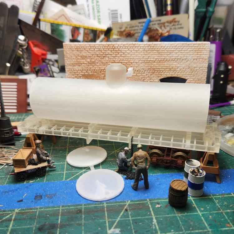 I was concerned about Pinlizardsl's comment regarding the resolution of the curved surfaces, but they turned out fine. The frame rendered well and feels reasonably stiff. The holes for grabs and NBWs rendered better on the ends than the sides. The tank and ends are reasonably smooth. I think a soak in acetone will help with a thin layer of Tamiya putty and some sanding. Maybe just the sanding. 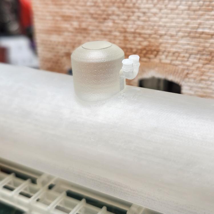 The dome and safety valve rendered very well. The plan was always to model the dome flange in styrene as I didn't think I could make the potato chip/ cowboy hat brim in SketchUp. Also, I have not had much success with rivets, so I will use my stockpile of Archer rivets to finish this model. The ends turned out well. I also struggle with SketchUp's "follow me" tool, and the part carefully rendered the goofy part of the model. Again, a bit of filler and some sanding and I am off to the races. Now for some time....
Keith Hayes
Leadville in Sn3 |
|
This post was updated on .
CONX 14 was built by the D&RGW for Continental Oil as one of three similar cars. The cars used existing tanks on new frames. The cars are distinguished by the walks on either side, and the handrails angled out from the car sides.
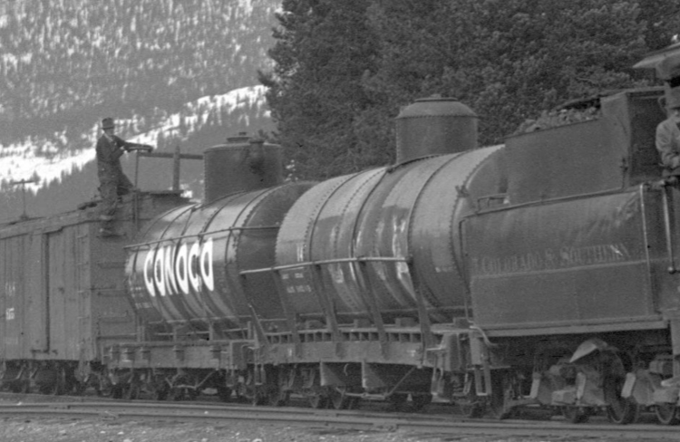 This image (which Chris found and I captured from another post) shows CONX 14 returning to Leadville on May 2, 1941. As trains usually returned to Leadville late in the day prior to the Climax operation being isolated, it was unusual to capture a train entering the Cloud City. Evidently CONX 5 and 14 were sequestered for this service as the end of operations. There were also some other cars built to a similar design, using other tanks, that survived in water service on the D&RGW. CONX 17 is one of these. The photo in the Dorman collection shows an archbar truck more similar to the C&S design than that used by the D&RGW. FYI, I am loving that brakie, kneeling on the end platform with his hand on the club and ready to break. Or maybe he is just hanging on? I observed an engineer shunting cars in Chama a while back often sat on the armrest and leaned out of the cab to look backwards as he was switching. I have seen the same thing with 20 and 346 in Golden. I think I need to cut up some engineers and move them out of the traditional seated positions. But that is another project. 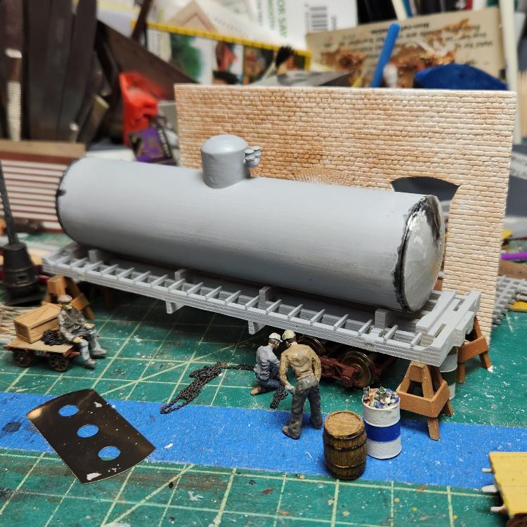 The model is starting to look like a tank car. The resolution was reasonably good, but an application of Tamiya primer showed some flaws. There are a couple coats of Primer on the model now with some plastic filler in between. Weights were epoxies inside, and some epoxy was added to the ends to beef them up internally. I was overly stingy on the thickness of the end for some reason. The ends are glued on with black CA, which will fill the joint and can be seen as it is sanded down.
Keith Hayes
Leadville in Sn3 |
|
Fascinating project, Keith!
The new printing techniques are becoming game changers in railroad model building. A lot more fun than building up yet another 3000-series D&RGW boxcar. Steve Guty is collaborating with me on a couple of printed projects (actually, he's doing all the work, I'm just kibitzing and offering photographs and moral support). Perhaps he will share some of his projects on another thread. I'm having my own adventure building up and detailing another 3-D printed car. Since I usually never finish projects like this, if I get further along, I'll share my experiences on another thread.  Keep up the inspiring work, Jim
Jim Courtney
Poulsbo, WA |
|
In reply to this post by Keith Hayes
Now that the Narrow Gauge Convention is over, it is time to return to modelling. CONX 14 got set aside as I cleaned up the layout for visitors. All the holes are drilled through the frame and the tank is sanded and primed and glossed up so I can place the vinyl rivet decals.
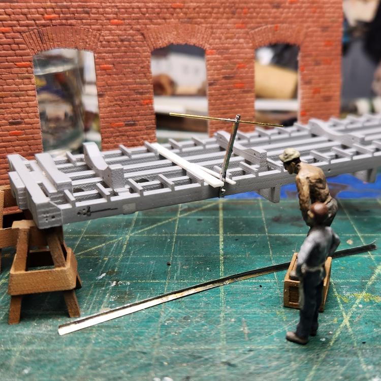 One feature if the prototype that is very appealing is the home made handrail that extends along each side. This is fabricated from 2" or 3" angle. Once again, time has been my friend. At the convention Simpson had packages of 3/8" x 3" brass strip. I bought a few and tried to make my first angle today. True confession: this was really fiddly. I need to make 10 of these and the end brackets also have a diagonal brace. I made one so it stands to reason I can make ten of these. Then I can take on the baggage car and the Pullman line car.  This is supposed to be my last scratch build for the MMR Rolling Stock AP. Model Railroading is Fun...Model Railroading is Fun!
Keith Hayes
Leadville in Sn3 |
|
Taking a page out of the Pat Student notebook, I figured it would be easier to make my brass angle if I created a jig.
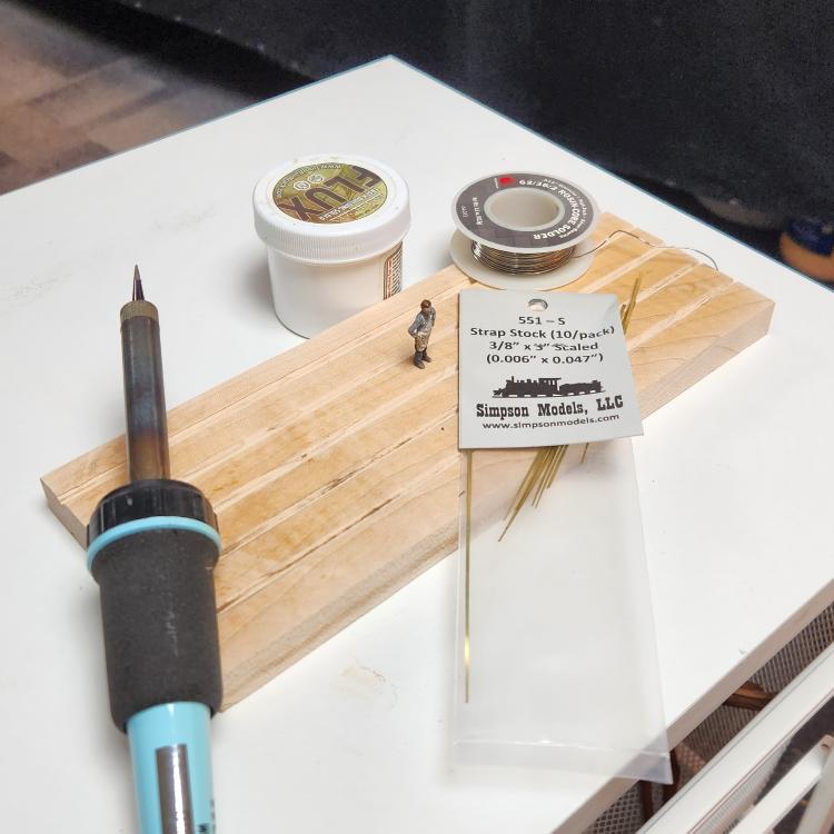 So I dug out the table saw, found a scrap of tight-grain Maple and cut some 45-degree slots. The brass strip was roughed up with a sanding stick, which also flattened and straightened the strips. I set the strips in the jig, applied a liberal amount of Flux and some short lengths of solder and quickly created four lengths of angle! 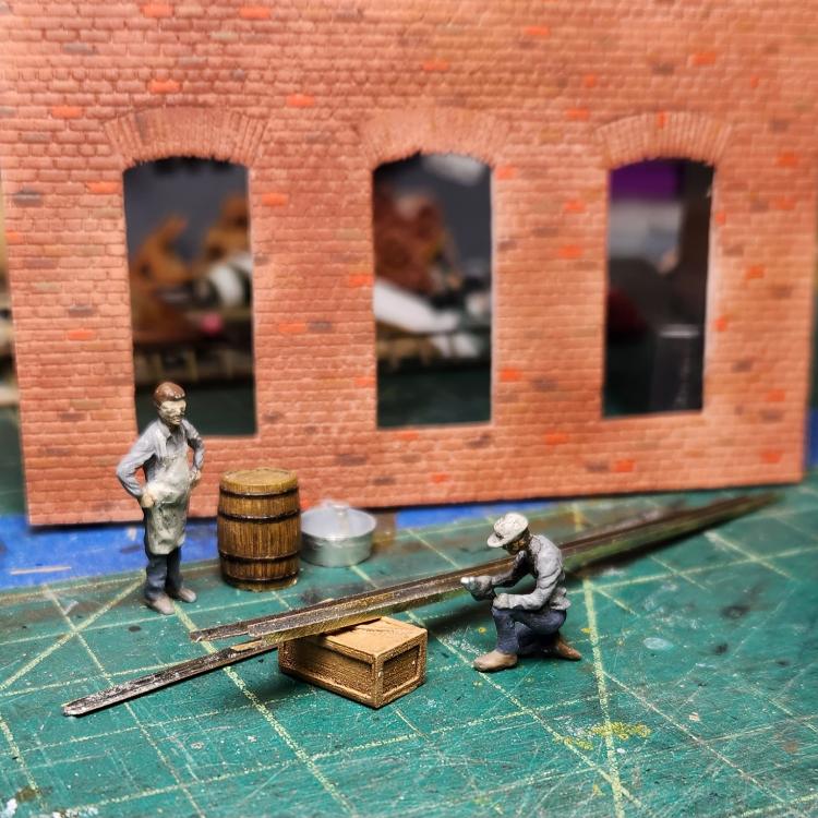 Now that is done. Next up is cutting 10 pieces to length, drilling holes and bending the pieces. All with pretty tight alignment.
Keith Hayes
Leadville in Sn3 |
|
I'm impressed Keith.
 you're going to have some fun with those struts Mate. you're going to have some fun with those struts Mate.
Timely insert...which shows both sides of the end staunchions...in the full picture  DPL Rh-1750 enlargement 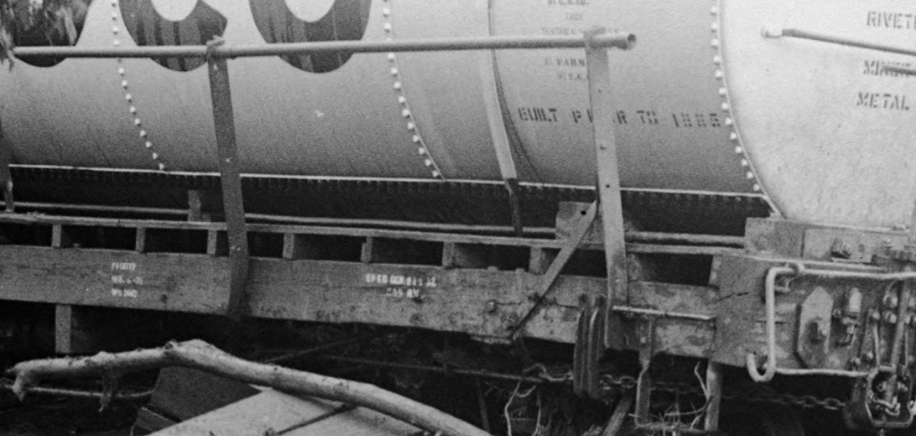
UpSideDownC
in New Zealand |
|
In reply to this post by Keith Hayes
Keith,
You are my hero. You are a true narrow gauge scratch builder. Way to go. Lee Gustafson |
|
In reply to this post by Chris Walker
Perfect, Chris, thank you.
Happy to oblige, Lee. 
Keith Hayes
Leadville in Sn3 |
|
This post was updated on .
In reply to this post by Chris Walker
Withe the angle assembled, efforts turned to fabricating each stanchion. The angles were first cut to length. Then the pieces were filed and sanded again. Holes were created in the frame for a brass wire for support and strength and these were laid out at the bottom of each angle. Then the holes for the rail were laid out and drilled at the top of the angle. The machinenist's vise was invaluable for these steps.
The photo of the silver tank above is CONX 19 in Morrison after a flood. The close up of the rail is great, but comparing 19 to 14, the angles are laid out differently. 14 appears to have the end stanchions with the back of the angle facing the center of the car. 19 is opposite. The photo indicates that the diagonal brace is bar stock and not an angle. I cut some of the Simpson 2" stock into 5' lengths, which is oversize. The ends were tinned. An end angle was placed in the vise and I marked the position with a Sharpie. A 60 degree angle seemed about right. The tinned bar was placed on top and held with a weight. 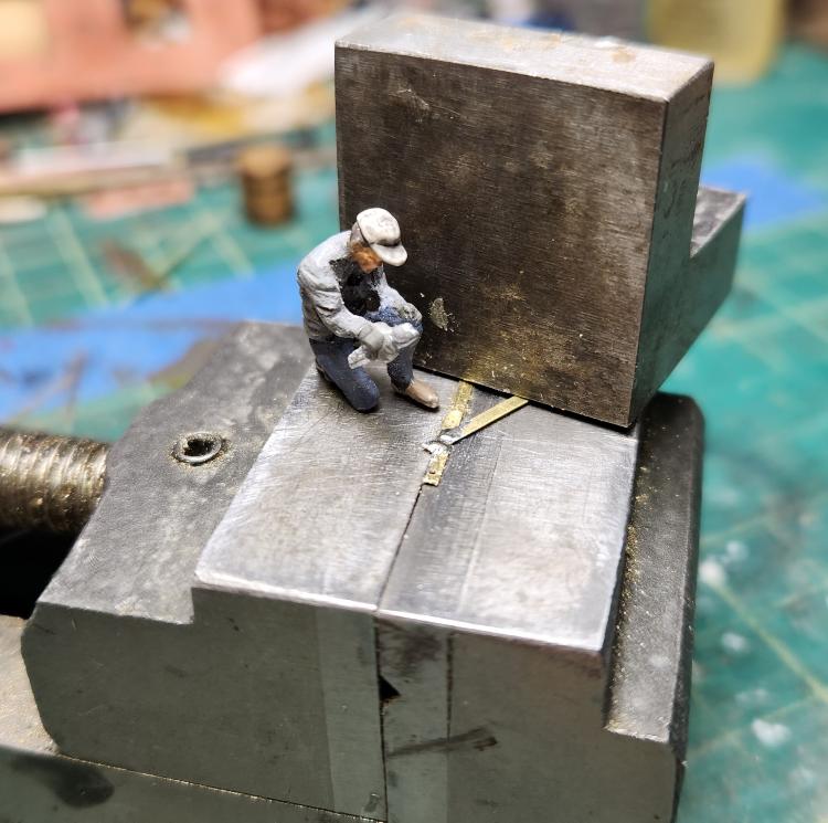 This worked well and in no time the four end pieces were completed. The bar was bent up using a razor blade and a weight. CONX 19 stanchions also have some additional holes in the, implying the use of recycled material. You can see this in the CONX 8 frame and D&RGW 6200 flat car frames. (I have not taken a drill to CONX 8...yet.). Anyhoo, here is the result! 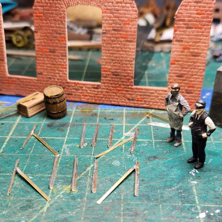 Slow and steady wins the race. Flux helps, along with holding the parts so you have two free hands. After a break, more progress. The brass rod was added to each stanchion to better stabilize the connection at the car. Then it was time to assemble the whole hand rail. 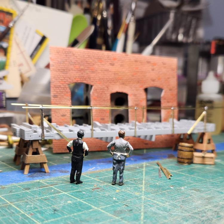 The stanchions were placed on the rail and the whole assembly was added to the frame print for soldering. 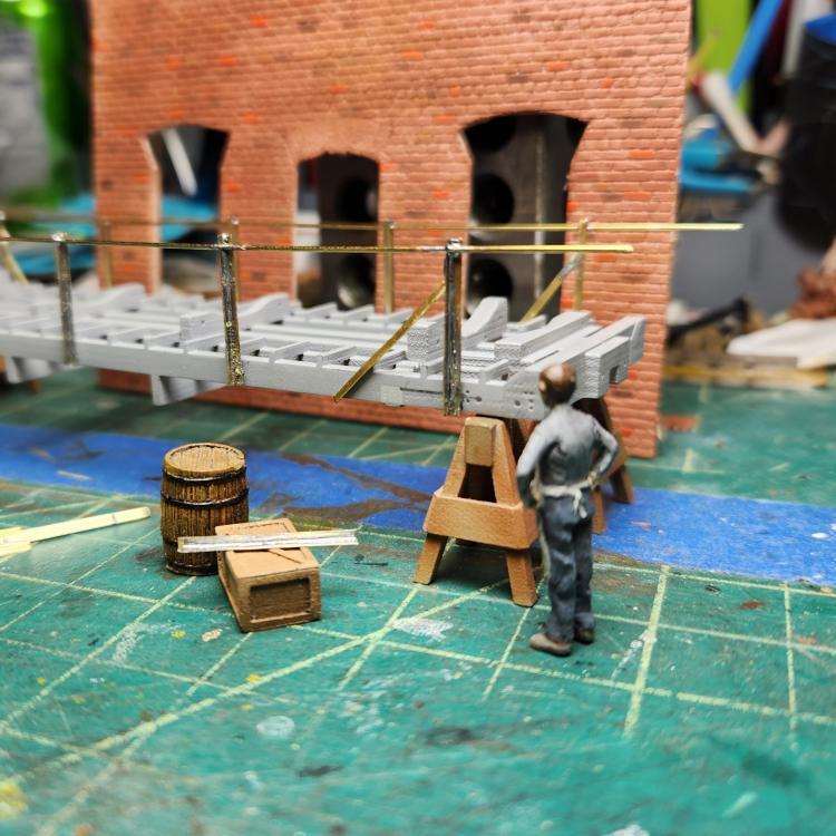 The rails will be trimmed later. Then the frame was flipped and the second rail assembled. The soldering was very quick, with a dab of Flux and barely any heat required! 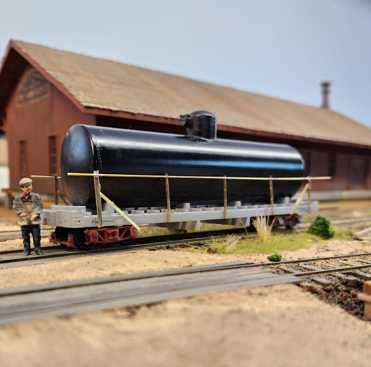 It is the funky rail that really attracts me to this car. It was fiddly to build, but a great challenge and I am happy thus far with the results. Now to carefully bend the angles outward. 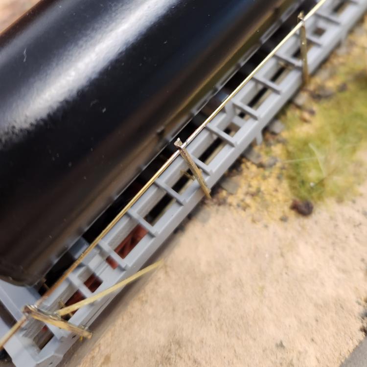 I guess it is time to put the rest of the jewelry on the car frame. Then I can return to the tank.
Keith Hayes
Leadville in Sn3 |
|
Tanks for these posts, Keith! they are inspiring.

Jim Courtney
Poulsbo, WA |
|
In reply to this post by Keith Hayes
Truss rods are in. Now the slow process of applying NBWs and grab irons.
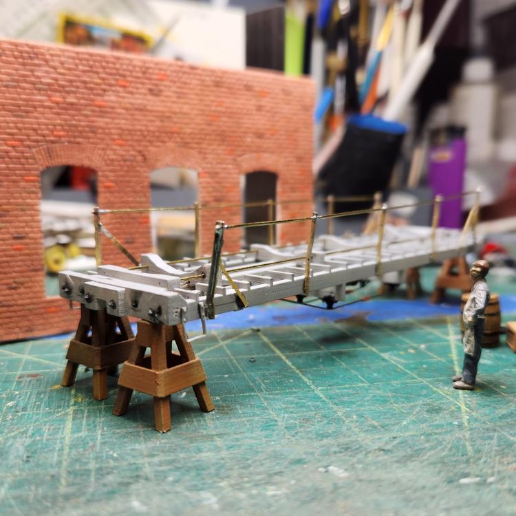 This will be followed by installation of the brake rigging and the crossover. I guess I should stain the walkway boards, too.
Keith Hayes
Leadville in Sn3 |
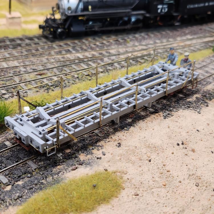 You might not be able to tell, but great progress has been made on the under-frame. The grab irons are all installed, along with the stirrup steps. All the NBWs are in place and the brake rigging and plumbing is complete. Where might the retainer have been? My money is on the end beam. Progress is also occurring on the tank, which is receiving lots and lots of rivets.
Keith Hayes
Leadville in Sn3 |
Indeed it was..... on the CONX 19 at least DPL Rh-1750 I linked earlier above shows it well.  Your underframe is coming along nicely, Keith. 
UpSideDownC
in New Zealand |
|
In reply to this post by Keith Hayes
Keith,
You are my hero! CONX 14 is making great progress and when it’s finished you will have a one of a kind model. Thank you for sharing your work and techniques. Lee Gustafson |
«
Return to C&Sng Discussion Forum
|
1 view|%1 views
| Free forum by Nabble | Edit this page |

