C&S RPO 11: Linn Moedinger’s Shapeways Print in Sn3 and Hon3

Previous Topic Next Topic
 
classic Classic list List threaded Threaded
105 messages Options
123456
Reply | Threaded
Open this post in threaded view
|

Re: C&S RPO 11: Security Bars

Keith Hayes
Jim, I did check the carbody--it is darn close to 36". As Mike notes, the C&S passenger fleet rode high.
Keith Hayes
Leadville in Sn3
Reply | Threaded
Open this post in threaded view
|

Re: C&S RPO 11: Security Bars

Jim Courtney
This post was updated on .
Ruh-roh . . . that doesn't bode well for my planned coupler and bolster installation on the HOn3 print.

But then again, in your last two photos, the thickness of the upper draft gear cover (plus what looks to be a shim) seems to place the top of the coupler shank just at the bottom of the end beam's lower edge.

Stay tuned, we'll see how it turns out in HOn3.
Jim Courtney
Poulsbo, WA
Reply | Threaded
Open this post in threaded view
|

Re: C&S RPO 11: Security Bars

Keith Hayes
Oh, yeah, I did use a coupler cover as a shim.
Keith Hayes
Leadville in Sn3
Reply | Threaded
Open this post in threaded view
|

Re: C&S RPO 11: Security Bars

Jim Courtney
Keith,

I would have guessed black, but according to the RPO 13 Quick Pic book, the safety bars were painted the same light ochre / buff / yellow, as was the rest of the interior (at least that's how it has been restored):


Mulina, Tim, Quick Pic Book: Colorado & Southern Narrow Gauge Baggage-Mail 13, BHI Publications, February, 2003.


BTW, the pair of slats on the floor lined in galvanized metal are the "fish racks" referred to in the folio drawings. In the summers, vacationers / tourists used the regular Denver-Leadville train to reach the various fishing resorts in Platte Canon. On their eastbound return to Denver, the RPO's could accommodate their catch.

If I were the mail clerk I might have a problem spending hours and hours surrounded by all that yellow . . .
Jim Courtney
Poulsbo, WA
Reply | Threaded
Open this post in threaded view
|

Re: C&S RPO 11: Security Bars

Keith Hayes
Security bars, check.


Keith Hayes
Leadville in Sn3
Reply | Threaded
Open this post in threaded view
|

Re: C&S RPO 11 in HOn3

Fritz 52
In reply to this post by Keith Hayes
These cars would really fit the bill since I am considering switching over to Hon3 from On30.
Linnwm:
The detail is in a word exquisite! What plans are there for printing the floor and undercarraige?
Fred
Reply | Threaded
Open this post in threaded view
|

Re: C&S RPO 11: Progress in HOn3 !!

Jim Courtney
This post was updated on .
In reply to this post by Jim Courtney


Wow, when Keith begins a model building project, he just keeps goin' and goin', hard to keep up with him.

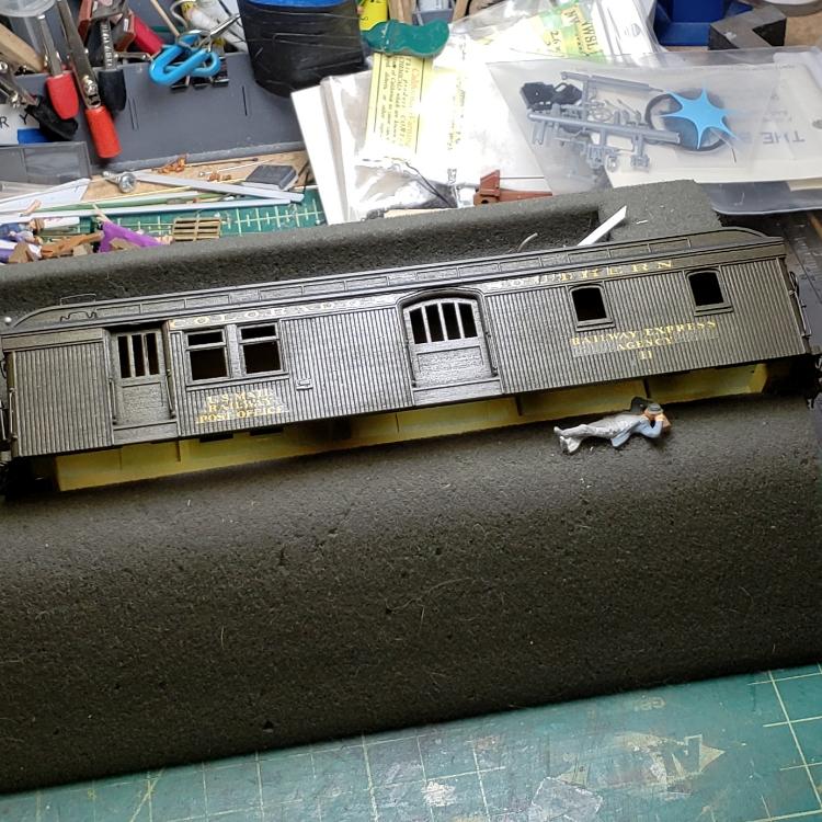
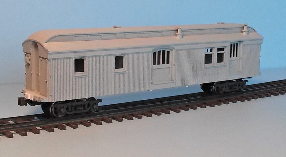
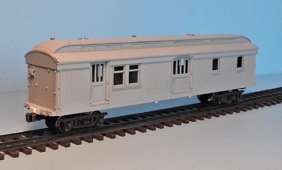
Linn is planning floors for all his HOn3 printed cars, but I was inpatient. After a couple of false starts, I finally finished the basic floor, bolsters, needle beams and coupler mountings. I modified Blackstone HOn3 J&S passenger trucks and mounted them, so now my little RPO 11 rolls.

I had two basic criteria for the floor: 1) The bottom had to set exactly flush with bottom of the sides of Linn's print. 2) The floor had to be removable but secured to the print, now and forever -- never know when you might need access to a finished car, to replace a broken window glass, or adjust the weight.


For those interested in taking on this project in HOn3, here's how I did mine.

Floor:

The printed RPO has two recesses for the floor, both 0.960" wide. The recess at the car ends is 0.045" deep (an inconvenient measure!). The center and bulk of the length of the recess is 0.10" deep. I cut the floor under sheathing from Evergreen 0.020" v-groove siding with 0.080" grooves, just a smidgen narrow and length to fit the full length of the shallow recess. To build-up the lower floor to 0.045", I laminated 0.250" wide strips of styrene (0.010" and 0.015" thick), and glued the strips to the outside edges of the floor bottom. I made a third strip just shy of the car length through the coupler notches, and glued it to the center of the lower floor, for a sturdy mount for truck and coupler draft gear screws.

The upper floor was cut from 0.030 thick black Evergreen styrene sheet to just fit the dimensions of the deeper floor recess in the print and glued it atop the three styrene strips of the lower floor. I added 0.020 inch strips cut from black styrene strip and glued them to the upper black floor (I didn't want all of the interior to be white or light grey when looking in the windows.)

This should have produced a sandwiched floor 0.095" thick, but with the five layers of glue welds, the final thickness happily turned out to be 0.10", a perfect fit.

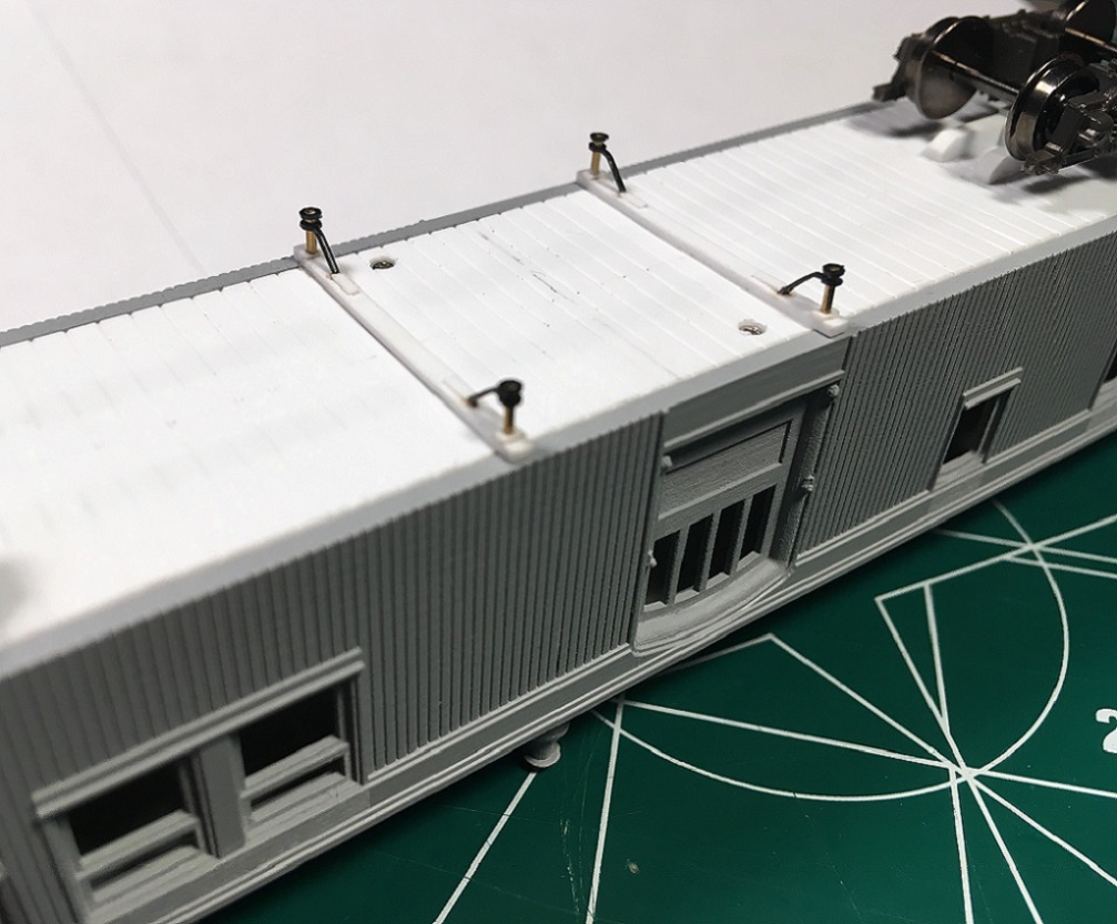
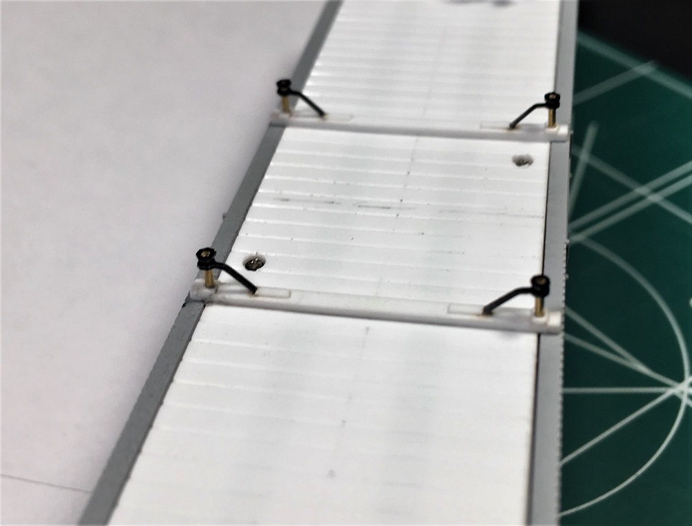
I laid out screw mounting holes at the four corners, like on a brass model, drilled them out with a #55 drill. Then laying the floor into the recess, everything lined up, I continued to drill #55 well into the printed body, and tapped those holes for 1.2 mm screws. The printed plastic seems a little denser than styrene, drills easily and accepts and retains threads well. A slight spread in the printed body's bottom was pulled into the floor edges using two similar holes tapped for 1.0 mm long screws. I located them near the center of the car in places where brake details wouldn't cover the holes. I will likely go back and counter sink all 6 holes so the screw heads aren't visible from the side.

Linn's print has 4 little indents, to accept 4 little tabs. The printed wall are fairly thick for strength, and I assume that these tabs are attachment points for the truss rod ends, so the queen posts and truss rod attachments can be inset the proper distance from the side of the car and still be attached to and removable as a part of the finished floor. I made the little tabs of 0.030" x 0.040" styrene strip, cut to length and attached to the edges of the floor, making sure that the bottom edge is flush with the floor bottom.

I laid out the longitudinal and perpendicular center lines on the bottom of the floor, and armed with Ken Martin's plans for RPO 11, I laid out the key landmarks: outside edges of the needle beams, kingpin locations for truck mounting to bolsters, the inside limit of the lower center sill extensions.

I followed Ken's plans and cut two needle beams from 0.030 x 0.060 styrene about 0.030" shorter than the width over the side sheathing, and attached them to floor so the needle beam ends were inset a bit from the car side, as in the prototype photos.
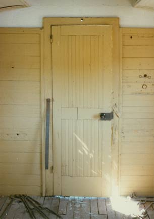

Couplers:

The end beams are built up an additional 0.020" below the floor, and a coupler mounting notch printed into the models. I really don't understand Linn's planned coupler mounting. I chose to close up the notch with a length of 0.010' x 0.100" styrene. I added a coupler buffer block of 0.080" x 0.060" styrene, the width estimated from photos of the real RPO 11.

I acquired quite a stash of assembled Sergent HO "scale" operating knuckle couplers a while back and used the Accurail #1031 scale draft gear for mounting them. (http://www.accurail.com/accurail/parts.htm). When I had test fit the draft gear with coupler in place, for the closest possible mounting between cars, I marked the floor and cut a length of 0.020" x 0.250" styrene and attached it to the floor as a coupler mounting pad. EDIT: For the couplers to sit at their correct height, a mounting pad that is 0.040" thick is required. I added a second layer of 0.025" x 0.250" styrene, but you could do it right the first time with 0.040"x 0.250" strip.

Holes were drilled and tapped to mount the draft gear to the pad/floor.


Bolsters:

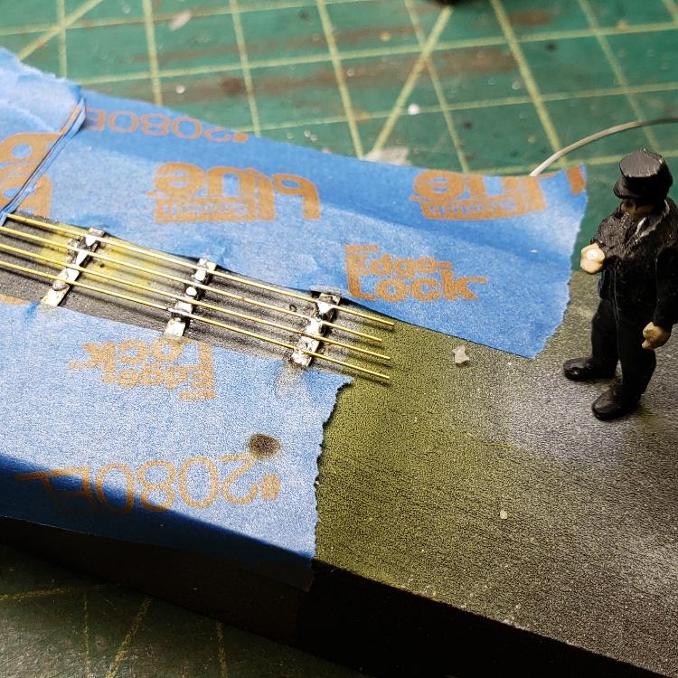
The wreck photo of RPO 11 showed that the lower extensions of the car's center sills extended back toward the needle beams a bit. The bearing surface of the bolsters on my Overland brass C&S passenger cars is exactly 0.100" below the brass car floor. To make my bolster assemblies, I sandwiched a bolster mounting block of 0.125" x 0.080" styrene between two sill extensions of .060 x 0.080" styrene, and attached them to the floor with MEK, the square, outside end placed snug against the couple mounting pad. To make the bolster bearing surfaces, I cut squares of 0.020" x 0.250 styrene, located the center with a needle in a pin vise, then drilled the king pin hole. The bearing plates were then carefully glued to the bolster base, to create a final thickness of 0.100". The final floor at this point:


The coupler draft gear mounting holes were drilled and tapped for 1.4 mm screws, while the truck bolsters were drilled and tapped for 1.7 mm screws
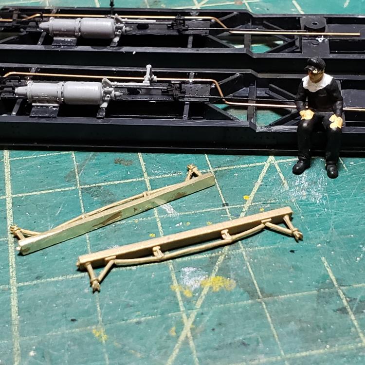

Trucks:

By the 1920's the RPO 11 rode on passenger trucks with inside brake shoes. Ken's plans note that such inside hung trucks had a wheel base slightly longer than the 5'-0" standard passenger truck, 5'-6", with a slightly different side frame. Well, guess what . . . nobody has ever produced 5'-6" wheelbase passenger trucks in HOn3 that I can find.

The Blackstone D&RGW Jackson and Sharp passenger trucks are very free rolling, with exquisite side frame detail, so I modified a pair for my little RPO 11. The conversion is similar to and actually simpler than Keith's conversion of PBL's Sn3 J&S passenger trucks for C&S cars. Two little screws secure the arm for the outside bearings to the truck bolster. These are removed and discarded. Four little locating tabs have to be removed so the truck bolster bearing surface is smooth -- I used sprue nippers and a small file. Finally, I used a sprue nipper to remove the truck end beam/brake beam parts. The diagonal brace to the outside of each truck pedestal was also clipped off, and the upper beam of the side frame was shortened at the ends to match the photos in the RPO 13 Quick-Pic book. The entire conversion took only 2-3 minutes per truck.

My modified trucks were attached to the floor with 1.7 mm pan head screws, which fit the truck bolsters perfectly. The bottom of RPO 11 with couplers and trucks in place:


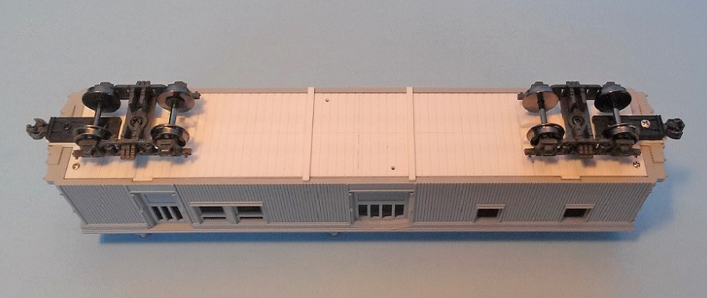
I placed my little RPO on a piece of flex-track, got out my dial caliper and measured the car height, from top of rail to bottom of floor. By happy coincidence a perfect 0.040" or 36" scale inches in HOn3, just like the prototype! 

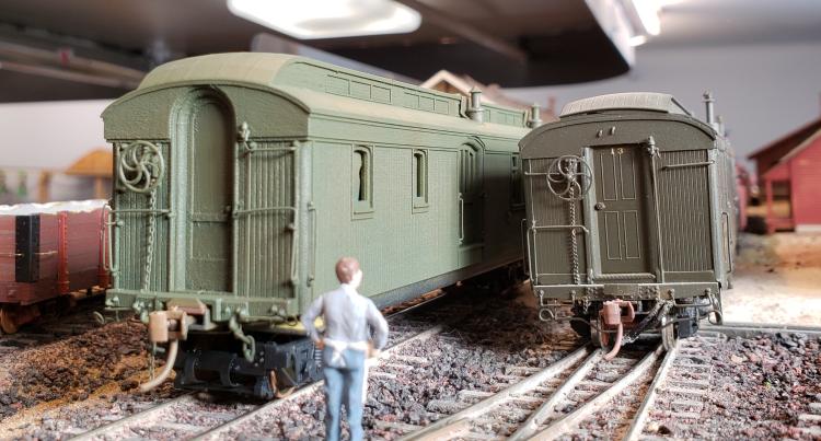
I was sure I would have to shim it a bit, but not so.  And the car height and coupler height matches those on my Overland brass cars nicely:


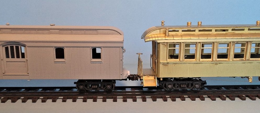
Modified Blacksone passenger trucks with outside brake beams are under the trailing coach. The couple height on both cars measures too high, though. I'm going to have to go back and add shims to the coupler draft gear on all my passenger cars, to lower the couplers to the proper 26" scale inches above the rail. EDIT: See corrected coupler mounting pad dimensions above.


Epiloge:

Building the floor/coupler/bolsters and mounting the trucks involved a lot of manhandling of Linn's print. Now that that heavy construction is over, the body and floor can be separated and go their individual ways for detailing -- adding the "jewelry" as Keith likes to say.

I'm sorry that I'm so far behind Keith on this joint project. I find that I have to build up each part in my head first, before I can produce anything credible in styrene, especially something this small.

I find it inspiring to put a model under construction in a train, just to see how it's going to look. Here is my (unpainted) westbound Leadville passenger train in June, 1927:


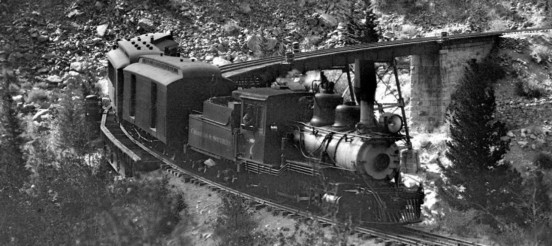
As a parting digression, I would note that every C&S RPO needs to be attached to a C&S Cooke 2-6-0. Here is my ongoing brass-bashing project in HOn3, the first that I've attempted since 1984:


This little locomotive will be C&S 7 in June, 1927. A couple of weeks before, she pulled the last passenger train down from Silver Plume to Denver on May 29th. After a week of routine maintenance in the Denver shops, with a pilot plow mounted, she is working Como turns on the Leadville passenger train for trials, before being assigned to west end passenger service out of Como, over Boreas and Fremont passes. There she will meet her fate, wrecked on snowy Boreas Pass in March of 1928. She never recovers from her injuries and will be scrapped in 1929.

Looks like she needs to have that arc headlight removed and a visor-less Pyle headlight added, don't you think?


But that is another story . . .
Jim Courtney
Poulsbo, WA
Reply | Threaded
Open this post in threaded view
|

Re: C&S RPO 11: Progress in HOn3 !!

Don Gustavson II
Jim,
Thanks for posting all that info on how you are putting this car together.
If I ever have time to put into actual trains and break away from layout building. This will be useful.
HOn3 is the path I have chosen.
The Nearly Historical Railroad.
http://www.nhrailroad.com/
Reply | Threaded
Open this post in threaded view
|

Re: C&S RPO 11: Progress in HOn3 !!

Jeff Young
Fantastic work, guys!
Reply | Threaded
Open this post in threaded view
|

Re: C&S RPO 11: Progress in HOn3 !!

Keith Hayes
In reply to this post by Jim Courtney
Jeez Jim, I guess I will take the compliment. I just keep my head down and do a little bit each week.

I ordered some Archer Resin Panel Lines and added these to the roof today.

The sheet metal guys also put the smoke jack protection over the clerestory.

I think the body is ready for the paint shop.
Keith Hayes
Leadville in Sn3
Reply | Threaded
Open this post in threaded view
|

Re: C&S RPO 11: Progress in HOn3 !!

Jim Courtney
Wow, the Archer lines really make the roof pop out! Are they available in finer lines (for HO scale)?

Any progress with needle beams and queen posts??

And have you figured out how to do the corner stirrup steps and the steps under the RPO and baggage doors?

One thought I had for the baggage door step: A PBL Sn3 freight car stirrup step almost exactly matches the baggage door step in HO scale -- was even outside mounted on the baggage door transom. Might an On3 San Juan or Grandt step work in S scale as well?

Ideally, etched brass steps would be just the ticket . . .
Jim Courtney
Poulsbo, WA
Reply | Threaded
Open this post in threaded view
|

Re: C&S RPO 11: Progress in HOn3 !!

Keith Hayes
Jim--Archer only seems to make one set of raised lines. They might have a finer set for N scale that you could use in HO. Check the website.

I am still waiting for San Juan to set up shop to get my needle beam-queen post assemblies.

I have also been pondering the steps. My first plan was to use K&S brass, but I cannot find the strip dimension I need. My local hobby retailer seems to believe that they can make more on HO diesels than scratchbuilding supplies. I have been waiting on an order of Evergreen 2x10 styrene for my Phase I coals for a couple months!
Keith Hayes
Leadville in Sn3
Reply | Threaded
Open this post in threaded view
|

Re: C&S RPO 11: Security Bars

Ken Martin
In reply to this post by Jim Courtney
If I were the mail clerk I might have a problem spending hours and hours surrounded by all that yellow . . .

I am not sure that it was that garish a yellow, here is a photo of the inside of baggage 2 when they first got it at Grand Island.

Ken Martin


Reply | Threaded
Open this post in threaded view
|

Re: C&S RPO 11: Progress in HOn3 !!

Keith Hayes
In reply to this post by Keith Hayes
Mr. Poole painted RPO 13 for me. He favors Scalecoat paints. I am having a devil of a time matching the color with Vallejo colors.
I thought Russian Green with a drop of brown would do the trick,  but it is still too bright.

I have some Tru-Color SP Olive that looks to be a close match,  but I don't have their thinner and it gummed up my airbrush.
Keith Hayes
Leadville in Sn3
Reply | Threaded
Open this post in threaded view
|

Re: C&S RPO 11: Security Bars

snapped_bolt
In reply to this post by Ken Martin

Hey...is that the caboose interior color I see?
   
   I watched the video that Chris posted a link to and sometimes the paint appears the same?

    Stan
Reply | Threaded
Open this post in threaded view
|

Re: C&S RPO 11: Decals

Keith Hayes
In reply to this post by Keith Hayes
Looking official with letters and numbers.
I got closer with my green and added a black roof.
Keith Hayes
Leadville in Sn3
Reply | Threaded
Open this post in threaded view
|

Re: C&S RPO 11: Security Bars

snapped_bolt
In reply to this post by Ken Martin


   Hi Ken,

       I was thinking that what was shown at the Museum by video was a little off. I would be expecting a somewhat more "institutional" tone. This looks like a harvest gold- like gone past the yellow stage.
       The video link-  https://flic.kr/p/ryrb2E    has incoming natural light, shining off walls painted (maroon?)- the level controls appear to be fluctuating as well be cause you can see the tone change as the camera pans around; at about :10 the seat changes to a harvest gold/tan color- the same is seen on the opposite side on the seat base.
       The closest match may be Model Master Radome Tan... once I grab some I will have a better idea.

       Cheers

         Stan
Reply | Threaded
Open this post in threaded view
|

Re: C&S RPO 11: Decals

Keith Hayes
In reply to this post by Keith Hayes
Lookee what arrived today!


And glued to the floor. Let the underbody detailing commence!
Keith Hayes
Leadville in Sn3
Reply | Threaded
Open this post in threaded view
|

Re: C&S RPO 11: Decals

Jim Courtney
This post was updated on .
Speaking of needle beams and queen posts . . .

The cast brass parts that Keith is using on his Sn3 RPO 11 were cast quite a few years ago, as part of a run of passenger car kits by The Cimarron Works. With the diagonal brace from queen post to needle beam and the small truss rod along the length of the needle beam, this arrangement was typical for most C&S passenger cars, including RPO 13 and Coach 70, as documented in the Quick Pic Books.

No such part exists in HOn3, so I had to figure out how to make them from scratch.

I studied the underframe photo of the TOC wreck of RPO 11 at Foxton (up thread) to see how the queen posts and braces were made. It looked to me as if the queen post braces on RPO 11 were different: The braces seemed to be attached a bit higher on the queen post, and the brace itself wasn't diagonal, more of an "S" shape, attaching to the queen post with a yoke or ring, running straight back toward the center of the car, then curving up and back, flattened and attached to the needle beam with bolts.

It occurred to me that the braces may have been replaced with a standard design (like Keith's) in the 'teens when the RPOs were rebuilt. It is extremely hard to visualize the queen post braces in the few later 1930's photos. But fortunately, Otto Perry rode the train from Denver to Leadville on snowy day in 1934, and took this photo:

http://digital.denverlibrary.org/cdm/singleitem/collection/p15330coll22/id/42479/rec/27


The same "S" shaped brace is in evidence in 1934.

I thought it would be cool to try to model this detail on my HOn3 RPO 11; this is what I came up with:


The queen post base is made of 0.010 x 0.040 Evergreen strip. The queen posts themselves are 0.019" brass wire. To model the braces, I used Tichey HO scale O-rings, that have a long plastic stem, the center drilled out to 0.020". The stems were bent upward around a drill bit for consistency, the stems trimmed and secured to the needle beams with MEK. The attachment to the needle beam is suggested with small pieces of 0.010 x 0.030 styrene (Tichey rivets to represent bold heads to follow).


The queen posts are located just above the seam between the car body sides and the styrene floor. I'm going to have to bend the truss rods from 0.015' brass wire and attach them to the queen posts and the floor at the 4 little tabs created earlier. I used a second Tichy O-ring with stems removed at the very bottom of the queen posts, hoping to cut off the web of Grandt plastic queen posts and secure them to the bottom of the queen post with MEK -- so far that hasn't worked.

Whew! All the time doing this tedious stuff with loops can give a guy a headache. Perhaps I should have done an Sn3 car instead . . .


Jim Courtney
Poulsbo, WA
Reply | Threaded
Open this post in threaded view
|

Re: C&S RPO 11: Decals

Keith Hayes
Jim, that is a lot of work to make the queen post braces, but the results look great. I am not sure how the prototype castings function with the 'S' curve in them: they look elegant,  but the bend seems like it would not be effective as a brace.

The Cimarron castings are a bit wide for the print. I epoxied them to my floor last night. They have a nice NBW cast into the end of the needle beam. Studying the photos I didn't see this bolt and noted the ends of the beam appeared rounded. Filing off the NBW and rounding the ends shortened the beam sufficiently.

I strung the truss rods today and here is where the car is before I add the brake rigging.


I am using RPO 13 as my brake rigging pattern. Though it may represent the prototype, there are some odd connections that don't make sense initially.  Stay tuned.
Keith Hayes
Leadville in Sn3
123456