C&S #30, a C-16 conversion

1234

1234

|
This post was updated on .
Hi all,
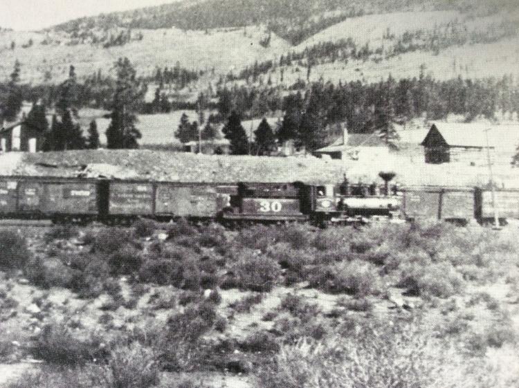
I'm working on a project that might be of interest to those modeling the early C&S years. I'm gradually converting an HOn3 C-16 to model C&S #30, circa 1905. Most of the photos I know of of #30 are in Vol. VI of Grandt's Narrow Gauge Pictorial, on pages 78-81. The first two are from 1902 when the engine had the intertwined "columbine" lettering, had a single air tank on the boiler, and still had its short smokebox and McConnell stack. The other two photos, which have been published several times and are in the Salida Archive online (in great scans with maximum detail) are from 1910 when it worked on the Alma branch, as it apparently did for most of its C&S life. By then it had the modern lettering, the extended smokebox, and at that date the "diamond stack of 1910", and the second air tank had been added. I'm going for the short period in between that is pictured in the photo at Como when the engine was derailed. This has been attributed to several dates in different publications, but probably 1905-6 is right, I think-? Here's an enlargement of #30 in that photo: 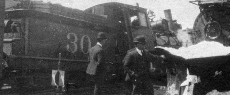 #30 then still had the single air tank, but the new stack (and, surely, the extended smokebox), and still had the Columbine lettering. I'm finding myself more and more interested in this time period, when so much was changing on engines, and a lot of the inherited rolling stock was still in service in varying states of dilapidation. Well, here's where I have gotten so far with my model: 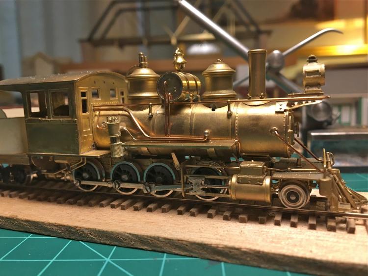 I started with an old Westside C-16 #278 from the mid-1970's. These are plentiful on Ebay, and you can still get a nice one for $200 if you're patient. I bought a nice one a while ago to detail using Kemtron C-16 parts given to me by my best old friend who 50 years ago introduced me to the Colorado narrow gauge roads. Baldwin built the C-16's and the engines that were originally DSP&P #s 190-197 to nearly identical basic dimensions. D&RG 278 was built in 1882, while DSP&P #190, which became C&S #30, was built in 1880. I got excited about making a #30, which was the only one of its class to last long enough to be called a B4A on the C&S, so I watched Ebay until I found another Westside C-16 in rather poor shape, but it did have what looked in the photos to be very neat soldering that would ease the disassembly and cleaning up for the conversion. And it was cheap! Here's what it looked like when I got it: 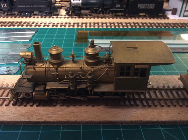 This one was very dirty and a bit sad, but these are nice little models. Their main shortcoming was that they had a huge open-frame motor sticking out of the cab: 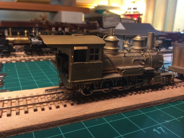 Here's what it looked like stripped of its Rio Grande hardware, and with the cab floor and windows modified to the new form: 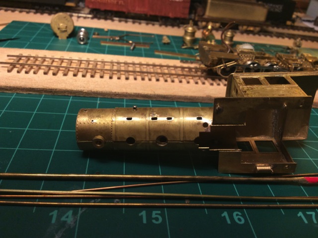 There were a lot of holes to fill. The round holes I filled with suitable size rod or wire, and the rectangular holes I filled with .030" square stock, cut with tapered ends so that it pressed in tight against the ends of the hole. This held it in place easily for soldering. The next photos show this process. 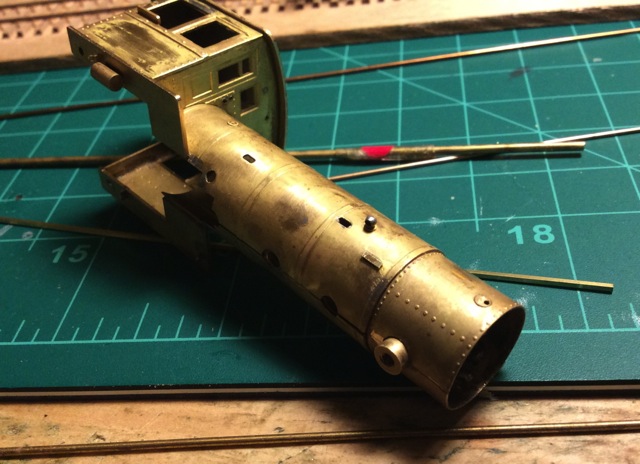 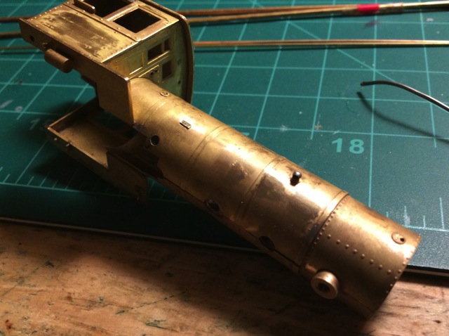 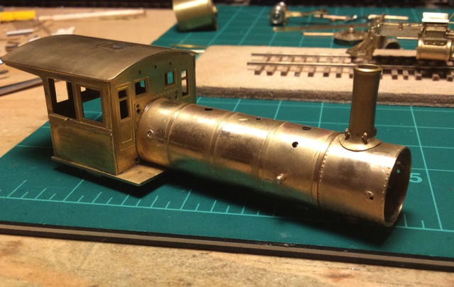 I had to move the washout plug on the engineer's side because it would have been behind the air pump. This probably looks like a lot of work but it actually went quickly, and it was a very fun evening watching the holes disappear as the jeweller's file shaved off the nubs. I didn't use any abrasives, to keep a nice smooth surface. I did use brass cleaner/polish to get the oxidation and dirt off before I started soldering. Next it was time to start on its new life. There are unfortunately very few correct parts available in HO scale. I made the air tank and its mount (which was hard to get the right shape, took a couple of tries), and the most crucial part of the South Park identity, the headlight bracket. Here are a couple of closeups: 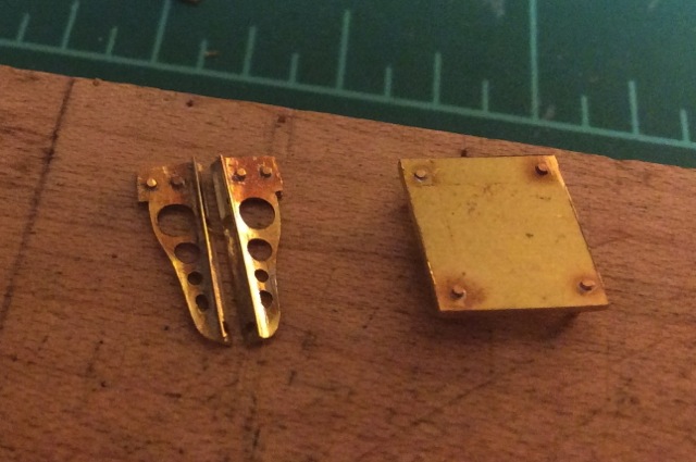 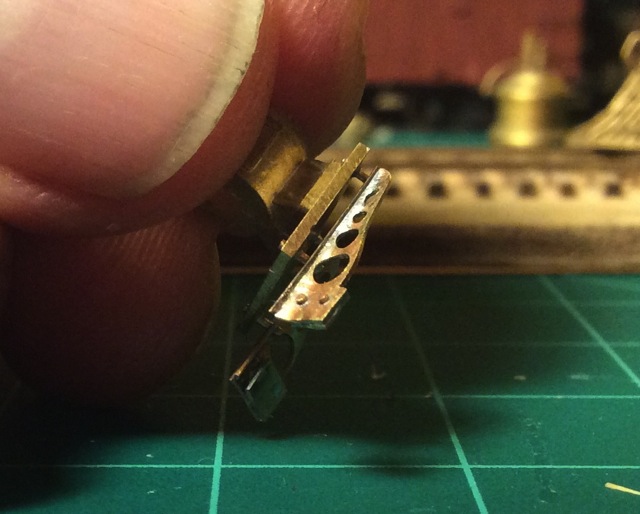
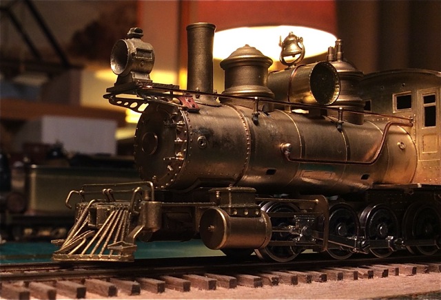 I had already found with the first C-16 that it was just exactly possible to fit the superb Faulhaber 1331 motor into the boiler-- if, and only if, all the inward projecting tabs and posts of the mounted parts were filed away inside. The original gearset is used, but the idler gear has to be moved to mate with the different worm position. I found an easy way to do this accurately without machining. If anyone is interested I could show how it works. The result is an amazing running engine that can start up almost imperceptibly and has way more than enough power for the available traction of this little HOn3 engine. It can pull a train along smoothly at a speed of one tie in 20 seconds. Incredible! This re-powering was quicker to do with #30 because I had removed from the boiler all the inward-projecting hardware. That saved an hour or so of awkward filing. This also allows me to have a backhead. I used one, and a nice cab back, from my donated collection of C-16 parts. The old Kemtron cab back fit perfectly on the Westside cab with about two swipes of a file: 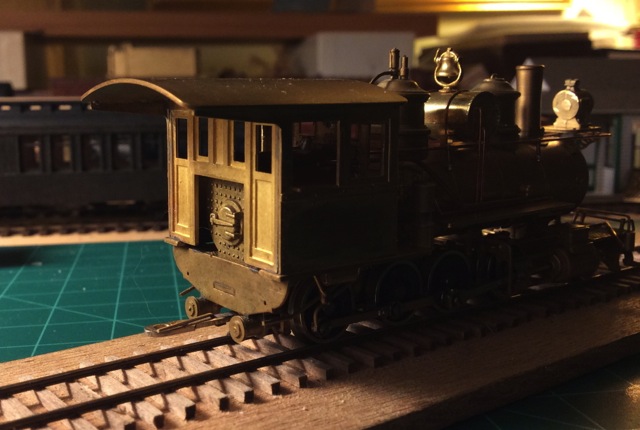 I'll redo the back of the cab floor and the frame support when I do other work on the frame later. There's a lot to do. I need to make a new stack, a new firebox front, a new pilot.... This brings me to a question. What should the pilot deck area be like on this engine? It's hard to see in the photos I have, but it looks like there was no decking between the cylinders and the pilot beam. Is that right? I need help with this. A second question: should this engine have a canvas-covered roof? I don't see any sign of a cab roof vent. Is there none? Also, please let me know if I've made mistakes in what I've done so far. The nice thing about brass construction is that it can always be changed! And, finally, I'd be extremely grateful to know of any other photos of #30. Anyway, I'm enjoying this project greatly, and I think now my #30 has got the beginnings of a proper C&S identity. The comparison with what the D&RG did with their version (that one, #278, I'm making about as it was in the early 1920's) makes quite a contrast: 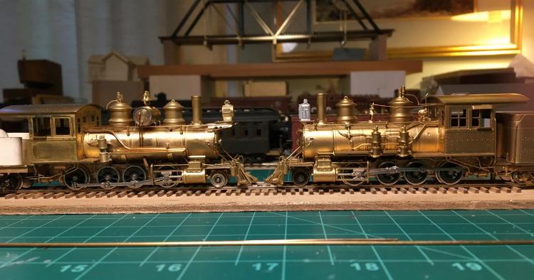 I think the C&S engine is better looking. Cheers, John
John Greenly
Lansing, NY |
|
|
Looking great!
Like you the 1900 to 1910 period was very attractive to me. I wanted a few of the earliest cars and a few of the steel under frames to depict the transition to the "modern" era. #30 certainly fits. Bill Uffelman
|


Re: C&S #30, a C-16 conversion
|
|
Can anybody show the photo of C&S 30 with a short smokebox and McConnell stack?
|
|
|
Here are the two 1902 photos of #30 from the NG Pict. Vol. VI:
 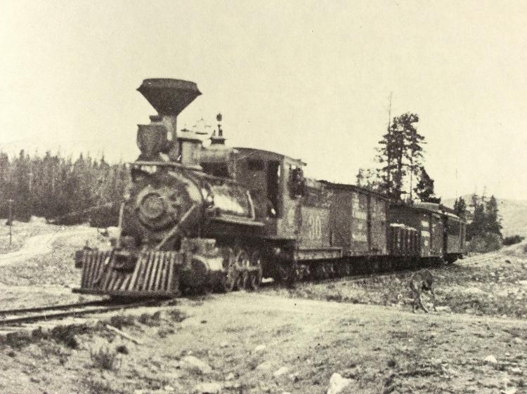 the two from 1910 are here: http://salidaarchive.info/salida-centennial-photo-archive/ scroll down the page until you come to these two images (about 16-17th mages down the page) click on them and then you can enlarge them further. Excellent detail. Here's the first one: 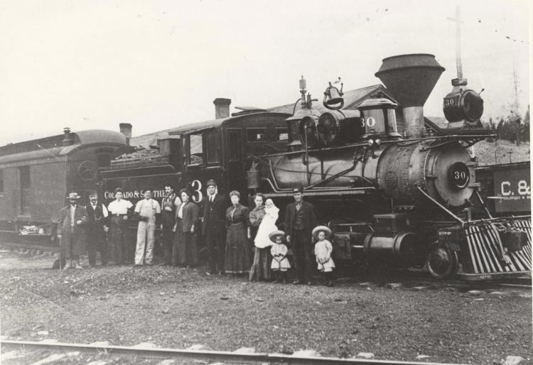 and here's a blowup of the pilot area. I don't see decking behind the pilot beam, but it's hard to tell exactly what's there. 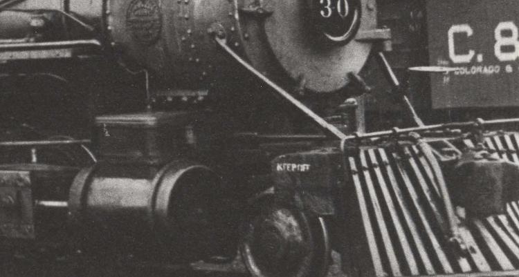 Can anyone help me decide how to do that part of my model? Cheers, John
John Greenly
Lansing, NY |
|
|
Wow, very nice work. Good clean work area too, not like mine.
|
|
|
In reply to this post by John Greenly
With the extended smoke box a pilot deck would be easily fouled when cleaning out cinders.
Just my non-expert opinion. Bill Uffelman
|


|
|
In reply to this post by John Greenly
Class 57 is I think the same as a C 16 and they were used on the South Park in the early days.
|
|
|
From the research that I have done, and from what others have said, the C&S Baldwin 2-8-0's 30-36 (B-4-A) were, according to the folio sheets of a slightly different wheelbase than the D&RG Class 57 (C-16).
I read and seen a comparison of the C&S B-4-A's and the D&RG Class 56, and they seem to be a match as far as the mechanical specifications go, including wheel spacing, wheel diameter and boiler diameter. It would not surprise me if they were a stock Baldwin Design and all of them were initially built to the same spec's. There is a beautiful photo of an early version, DSP&P No. 56, sporting a two panel cab and typical Baldwin domes and a huge Nesmith stack in Mal Ferrell's South Park book on page 86. Note the typical Baldwin Light brackets under the headlight. On the page opposite, page 87 of Ferrell's Book, there seems to be the same class of locomotive at Hancock with the photo taken from the Fireman's side. Of note is no sort of Air Compressor whatsoever. Of course as time went on, the South Park ones later had the typical larger Sandbox and McConnell Stack. A photo of DSP&P 51, on Page 99 of Ferrell's Book, the same Baldwin Class also shows the two panel cab, Baldwin light bracket and same general configuration as DSP&P 56 shown a few pages earlier. When Kemtron was considering making a C&S version of the C-16 in HOn3, they cast a Steam and Sand Dome specifically for this variation as well as the large Congdon stack. The cabs, during the DL&G days seemed to sport the four panel cab sides below the window line. After the advent of the C&S the Metal Plate was placed over the side of No. 30's cab and of course moving the Air Tank from the back of the Tender to over the boiler. But I gotta tell you, that C-16 conversion looks good. Rick |
|
|
In reply to this post by John Greenly
Great stuff, John!
I'd love to learn the details about the re-motoring/movement of the idler gear assembly--I've got two of the Westside C-16s that I'd like to rebuild into B4Bs circa 1910, and a PSC C-16 kit that I've earmarked to become #30 in that same era. I was wondering if you'd looked at, and discarded for cause, the option of using the shorter Faulhaber 1319, due to its lower torque? Steve Guty Lakeway, TX |
|
|
In reply to this post by John Greenly
Incredible work, John!
 That little headlight bracket is a tiny work of art. You should always include a dime in your photos to give us a sense of size. And thanks so much for sharing photos of the process, not just the end result. Now I understand how to fill all the holes and slots on the boiler wrapper, should I move things around on my Sn3 brass conversions. My one critique of your #30 is that the stack looks a little too fat and too short. The top of the shotgun stack should be exactly 4 scale feet from top of smoke box to top of stack. Too avoid turning a "shotgun stack" years ago, before I became frustrated with HOn3, I approximated the shotgun stack by using a short length of K&S brass tubing (forget the diameter) cut to length, then used a nail set as a mandrel to produce the bottom flair, to fit the smoke stake base. I just gently hammered the brass tubing down onto the nail set until the correct bottom diameter had been produced. A loop of 0.010 wire at the top of the stack finished it. One other detail about turn of the century C&S locomotives that I only recently noticed, is the locomotive brake cylinder, lever and driver brake shoe arrangement. The familiar below the cab, horizontally mounted brake cylinders and levers, which "pulled" the driver brake shoes back against the driver tire, didn't show up until about 1909-1912. Prior to that, the locomotive brake cylinders were vertically mounted between the 1st and 2nd driver, underneath the running board. Somehow this activated back-to-back brake shoes, that pushed against the first and second drivers simultaneously. This was true on the newly rebuild Cooke 2-6-0's as well: 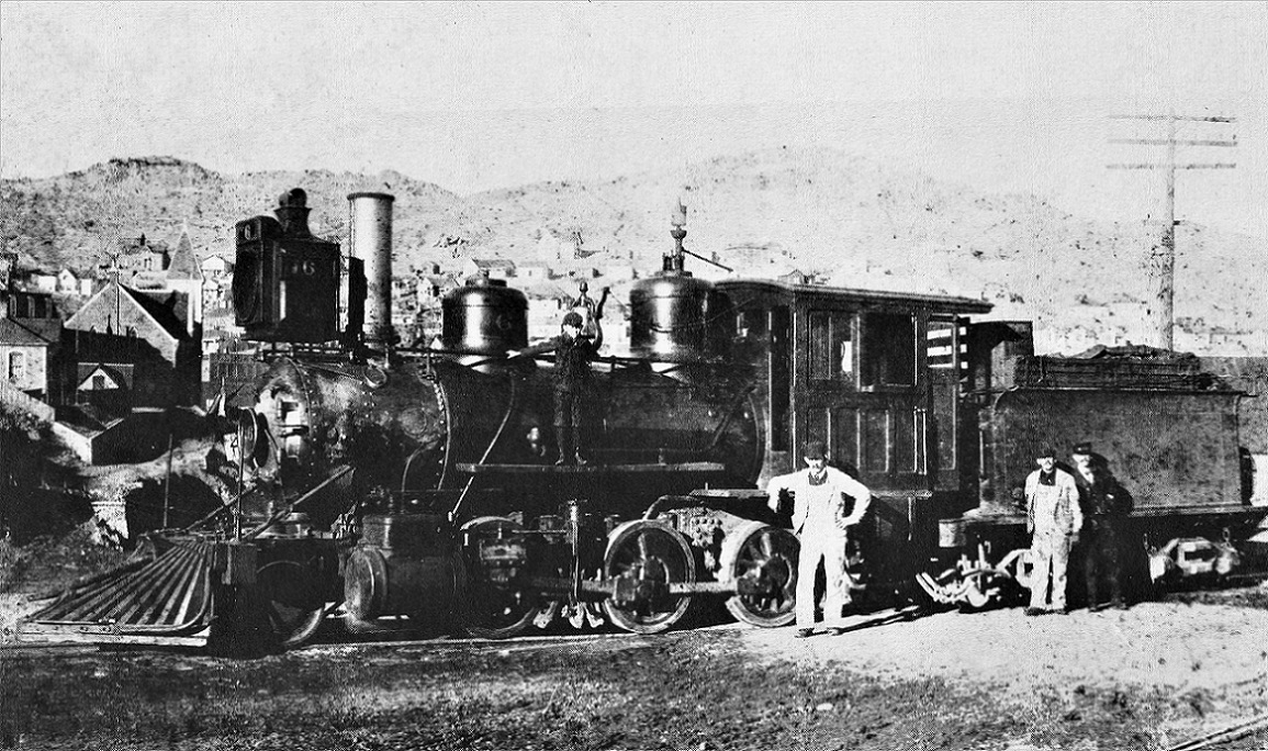 Number 6, 1900, before itsAugust 1901 rebuild. 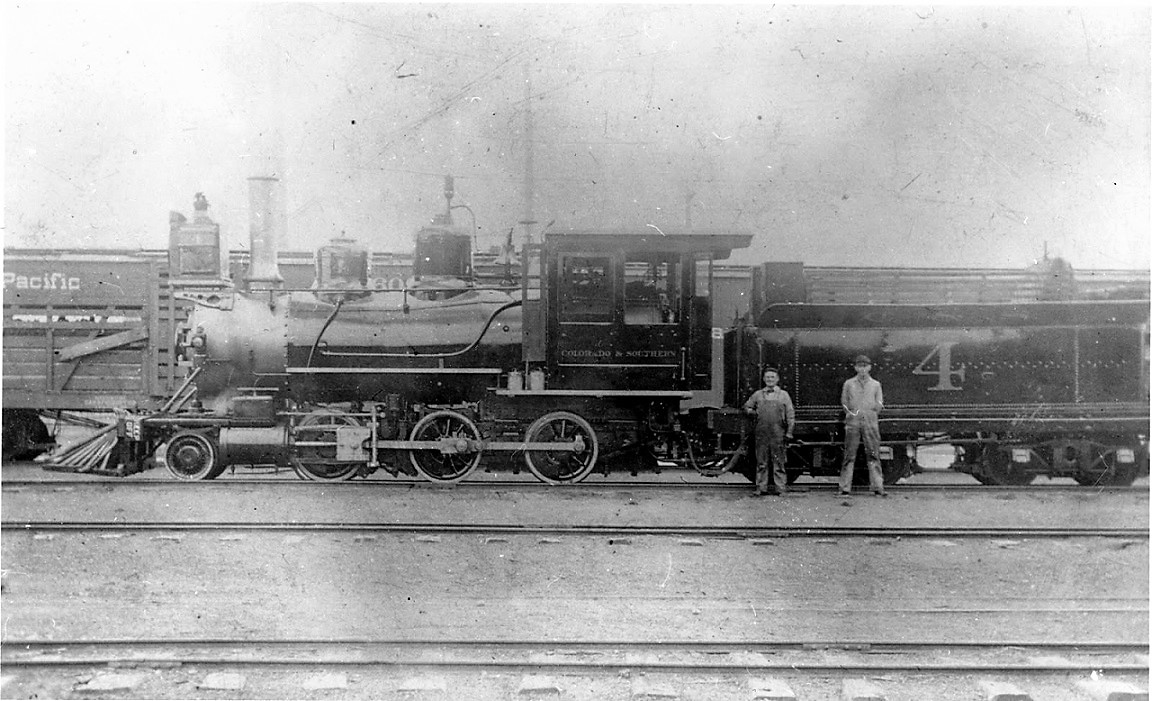 Summer of 1900, after number 4 was rebuilt, a "re-builders" photo in Denver.  The rebuilt Brooks 2-6-0's varied, with brake cylinder / shoes located between 2nd and 3rd drivers. 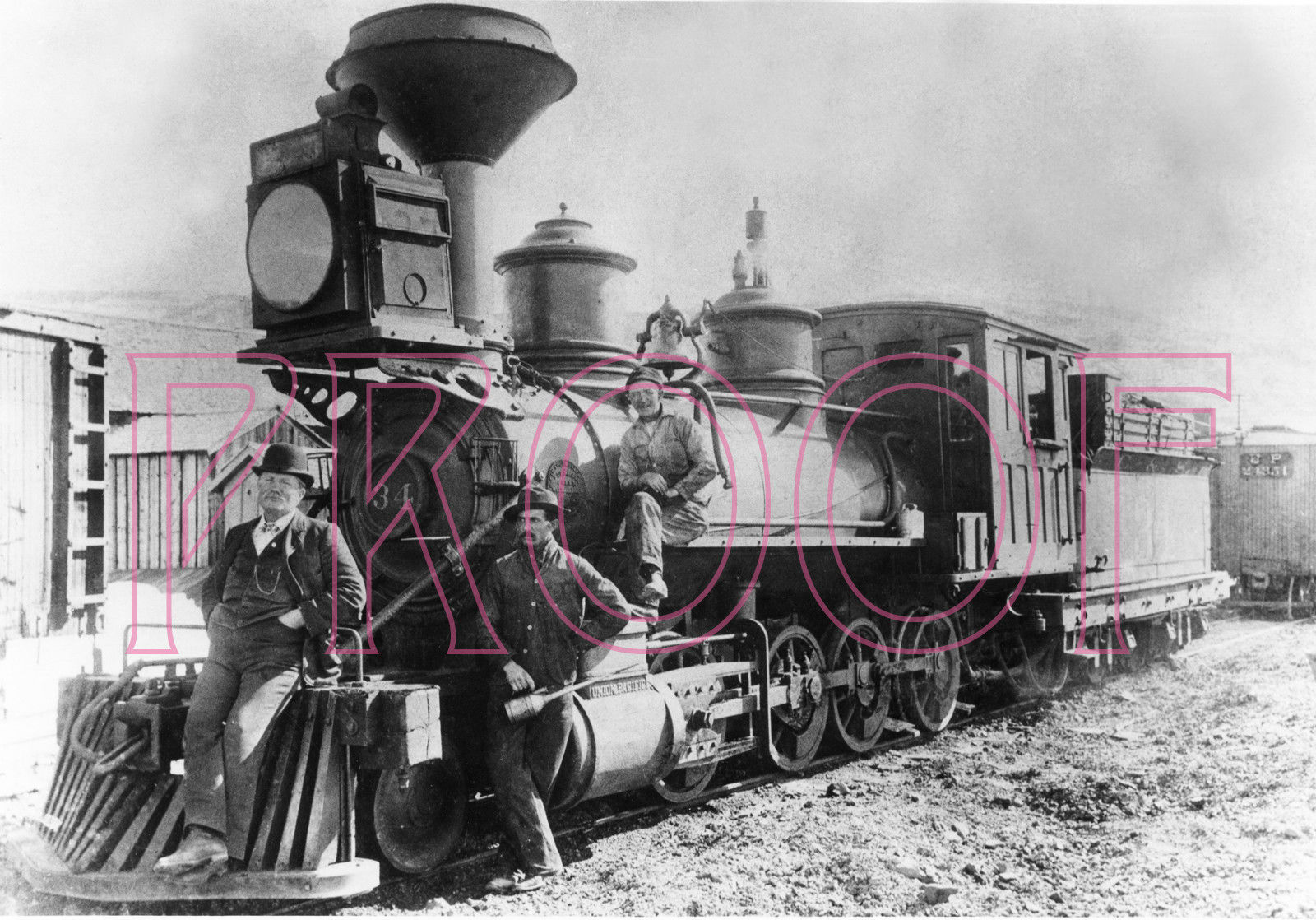 C&S Baldwin 34, sister to C&S 30, about 1900. The brake cylinder between 1st and 2nd driver is clearly visible. It is hard to know when the brake cylinder placement changed, as such details are usually lost in the shadows under the running boards and cab floors in period photos. Again, exquisite work John.
Jim Courtney
Poulsbo, WA |
Re: C&S #30, a C-16 conversion
|
|
In reply to this post by Rick Steele
Don't forget that in Nesmith stack days the Baldwins had Eames vacuum brakes.There are two different designs of Nesmiths on Baldwins- one with 51 on Palisade rock wall and the other with the Baldwin paired up with a combine at Hancock.Notice that as they got older several of the South Park Baldwins got their smokebox front replaced.
|
|
|
This post was updated on .
In reply to this post by Rick Steele
Hi Rick,
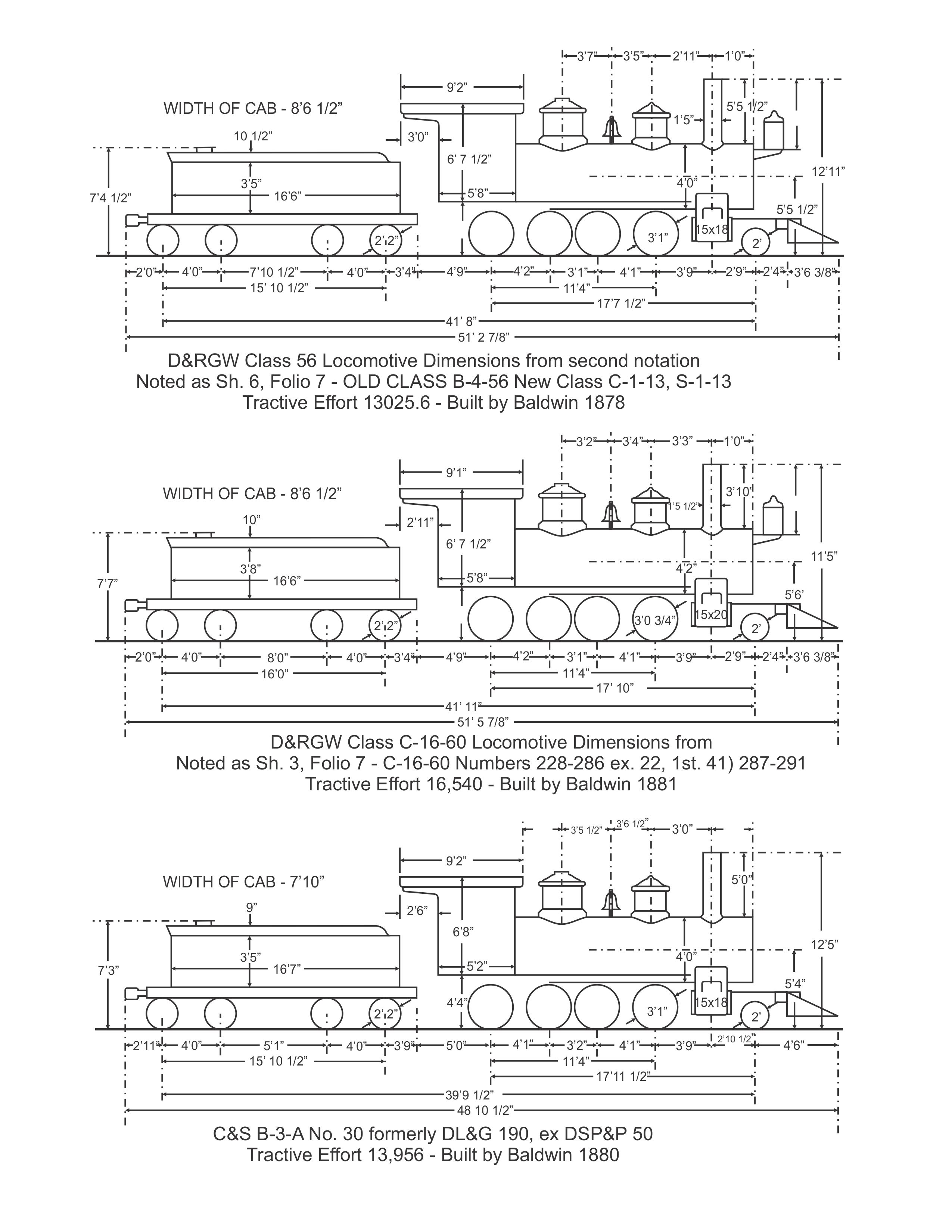
thanks for your comments! Your knowledge is certainly better than mine. I'll be curious to hear what you think of the dimensions I found. I used this data sheet compiled for the NMRA from folios and other data: https://www.nmra.org/sites/default/files/d4h.pdf This has the dimensions of C-16 (class 60) #278 which agrees well with the Westside model. This sheet also has C&S dimensions and I checked them against the (very incomplete) data on the folio sheets for B4A posted in the files here on C&Sng blog. The wheel spacing is not consistent between that NMRA sheet and the folio which shows the third driver 1" further back. Otherwise the spacings are identical to the C-16. The dome and stack spacings are a couple of inches different according to the nmra data, and I relocated the domes as given on the NMRA sheet for the C&S engine. Driver diameters are both given on the NMRA sheet as 37", but I have seen 36" for the C-16 elsewhere. The Westside model drivers are about 36.5. The boiler diameter of 48" of the C&S engine is indeed the same as the class 56, while the class 60 C-16 is 2.75" larger. As you can see, I didn't mess with that, so my model is a bit more stout than the real #30. A bigger difference is that the C-16 cab sides were 5.5" longer than the C&S cab. I decided to leave that alone too, so that's too long on my #30. The domes on the Westside model match very closely to the domes on #30 by my measurements from the photographs. The domes on the Cooke B4B's are substantially different, the sand dome is quite noticeably lower and fatter. Does all this seem correct to you? Jim, thanks for your info as always! The stack on my model is the C-16 one, and it is not right, I know. As I mentioned in the first post, that's on the list to make. The brakes are an interesting question indeed. That vertical cylinder brake arrangement was on the F&CC Baldwin consolidations (built a couple of years later) too, so I know a little about it. Unfortunately the brake mechanism is invisible in the photos of #30 in 1910. That photo of C&S 34 is a very big help, I've been using it. I haven't done much to the frame and underparts of my model yet, except to redo the saddle under the smokebox which was poorly done originally. Unless we find otherwise, I'll probably take off the brake cylinders and put in the vertical mechanism. The model has no brake shoes now anyway. Steve, I'll take some photos and post about the repowering. I had a Faulhaber 1331 on hand, and when I found I could fit it in, that's what I used. Thanks everybody for your comments!! John
John Greenly
Lansing, NY |
|
|
FWIW, here is a part of a drawing for the as-built Cooke 2-6-0's of 1884, showing the vertical brake cylinder / shoes. (Model Railroader, December, 1998):
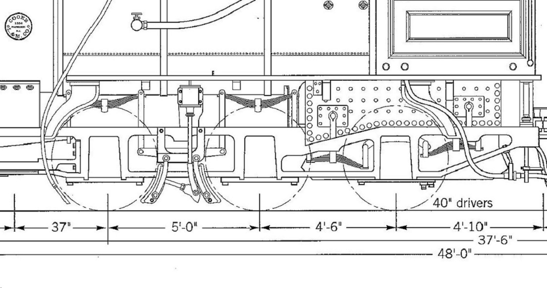 I'm still not sure how the mechanism worked. The brake cylinders on the 1900 locomotives seem larger than the drawing to me . . .
Jim Courtney
Poulsbo, WA |
|
|
Jim,
Being a vacuum brake would the cylinders work opposite to a compressed air cylinders-pull instead of push, the cam on the end of the rod would force the brake shoes against the tyres? Just guessing. That's a beaut looking model John. Paul R. |
|
|
Your're right Paul, the drawing depicts a vacuum cylinder and must be in error.
The Cooke 2-6-0's and 2-8-0's were all delivered with air brakes and 6" air pumps, the first DSP&P locomotives so equipped. The entire DSP&P freight car fleet was converted to Westinghouse air brakes in 1884, the narrow gauge by then under UP control. If the cam that the cylinder piston is attached, were drawn upside down, then the brakes would be applied with positive air pressure in the cylinder. Right??
Jim Courtney
Poulsbo, WA |
|
|
Jim,
Yes, but I think most of that type of brakes used a system of levers instead of cams, Leadville Shops had one in their castings I think you can still get them although that is in S. Paul R. |
|
|
In reply to this post by Jim Courtney
Jim,
here's what I think the basic mechanism of the vertical brakes was like: 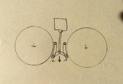 the rod from the cylinder pushes down, forcing the two angled links outward to apply force to lower end of the shoes, which are mounted to the frame with pivots at their upper ends. This adds mechanical advantage to the linkage. As I mentioned above, the F&CC 2-8-0s that Baldwin built also had the vertical brake configuration. They had the brakes on the rear pair of drivers. Here's an enlargement from a photo of one of them as it left to join the D&RG and become a C-18: 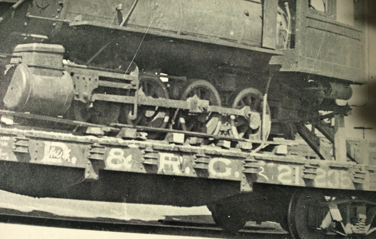 photo from CRA No. 13, p. 176. I have seen a better view than this somewhere else but I can't remember where at the moment. I think you can see the links I sketched. Does this make sense? John
John Greenly
Lansing, NY |
|
|
In reply to this post by John Greenly
Hi John,
The dimensions for both of those classes of locomotives came from a Publication of the NMRA Rocky Mountain Region called "The Helper". The initial date of publication was May, 1958 for the D&RG 2-8-0's and November, 1958 for the C&S locomotives. The interesting thing is that the wheel spacing on the drivers for almost all (the B-4-F class being the exception) of the consolidations was the same, for the drivers it was the same except for the 74-76. The pilot truck spacing varied from class to class. Of course, back then in HO, you were lucky for anybody to give you any notice. Fortunately, Larry Kazoyan at Kemtron came up with his C-16 kit and it became the defacto standard until PFM and Balboa started importing HOn3 from Japan. Back then the C&S 2-8-0 from PFM was the unheard of price of $49.95 and the C&S 2-6-0, also a PFM was $39.95. Kemtron also had an On3 version of the C-16. I didn't realize that those dimensions had been enshrined by the NMRA. I got to know both Emil Schmutzler and Billie Bowen when I was just starting in the hobby. If you look at the original sheets, it is stated by both Emil and Billie that they use folio sheet dimensions only and made no attempt to check them against any of the prototypes. Let me get on CorelDraw and see if I can make up a couple of comparisions. Rick |
|
|
Hey Rick,
this is great! Yes, I was surprised to see that the driver spacing was the same on all the classes B4A-E, despite their greatly differing boiler sizes and weights. That means, though, that the C-16 chassis could be reasonably used as a starting point for models of any of them. Hmmm.... It's nice to hear the background of those NMRA data. The folio sheets they had must have been different from the ones Jim Courtney posted here in the files section of C&Sng Blog. Those are missing a lot of dimensions. I remember when the ad from PFM for the C&S 2-6-0 first appeared on the back cover of Model Railroader. I REALLY wanted one, but $39.95 was way beyond my pay grade back then. I didn't know about the Kemtron kit until much later. I wonder what those cost originally? I look forward to seeing what you come up with in comparisons! John
John Greenly
Lansing, NY |
|
|
Here is the comparison, as promised. Not much difference even in 1:1 scale.
|
«
Return to C&Sng Discussion Forum
|
1 view|%1 views
| Free forum by Nabble | Edit this page |