C&S #30, a C-16 conversion
1234


1234
|
Here is the comparison, as promised. Not much difference even in 1:1 scale.
The file looks big, but it's actually an 8 1/2 x 11 size paper. (A4 for you, Chris) 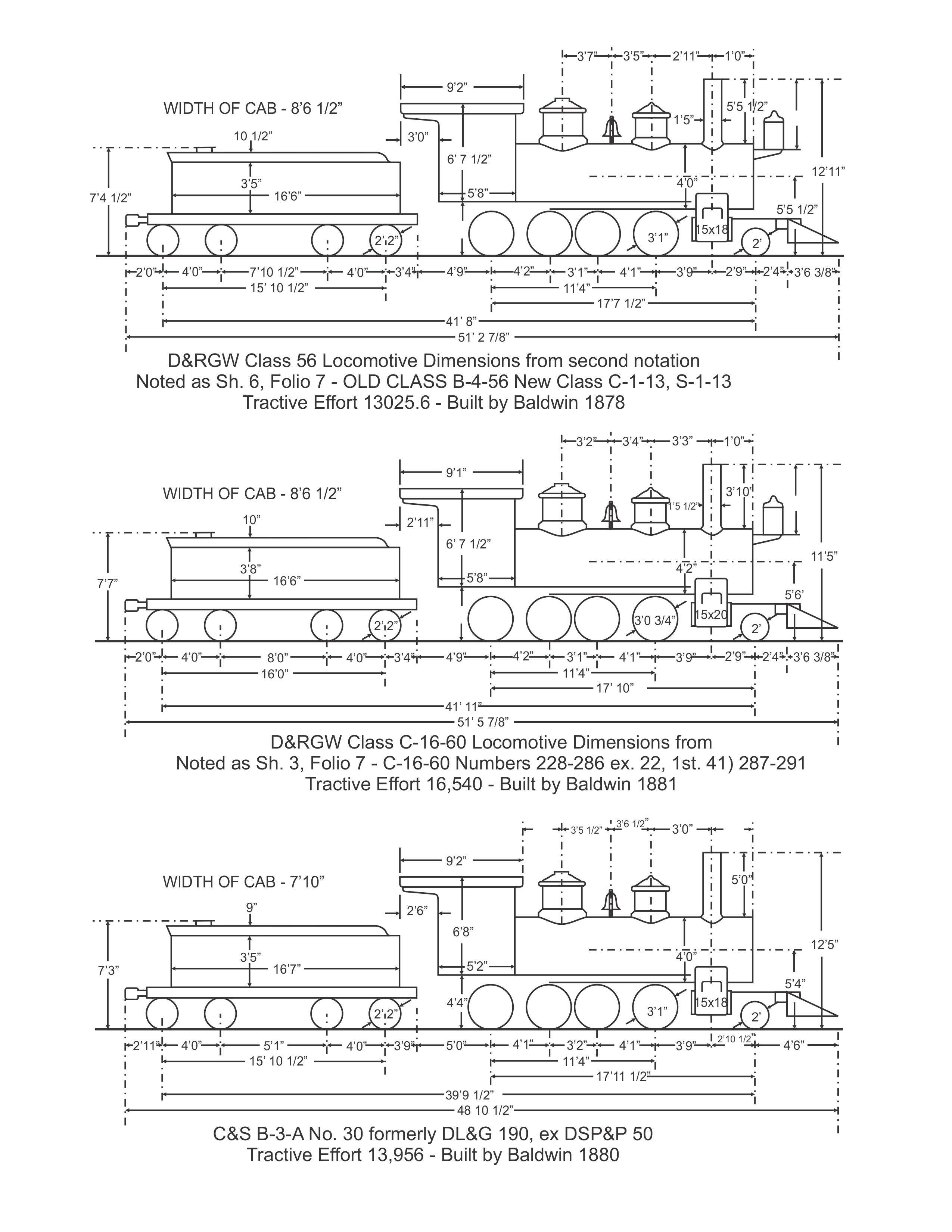 |
|
This post was updated on .
Rick,
wow, thanks for doing this! Several interesting things from my standpoint. First of all, I hadn't paid attention to the cab width dimension before this. The C&S cabs were much narrower at 7' 10" than the D&RG cabs at 8' 6 1/2". This made me go and measure the model, and in fact that cab is 8' 2" wide (outside width), just halfway in between the two prototypes! So I'll take that as a good omen for my #30. (By the way, I see that the cabs on both the PFM 2-6-0 and 2-8-0 are the correct 7'10"). At 8 1/2" narrower and 6" shorter fore-and-aft, we see that the C&S sure liked their cabs snug! I wonder why this difference from the D&RG? So then I got curious about other dimensions. I hadn't actually measured the wheel spacing on the model until now. The model driver spacing is actually 4'1", 3'3" and 4'1". For some reason they left a little more room between the middle drivers than the very tight spacing on the prototypes. Now I have to wonder about that. The 56 class showed as 37" drivers with a 37" spacing between the middle two. That's what I would call a close shave! Something is not quite right there. In any case, the model is actually very slightly closer to the B-4-A than it is to the C-16. Microscopic differences in HO scale to be sure, but still, more luck for me! Now I have a question about boiler diameter. Would that given dimension be the outer diameter of the boiler itself, or the total diameter over the lagging and sheathing? On the Westside model the smokebox is 4'2" diameter, agreeing with the C-16 data dimension, while the boiler is almost 4'6". If that's correct, I guess it implies that the given dimension in the data must be the bare boiler diameter. What's the right answer? Here's one very minor correction for your drawing, maybe? I had noticed one other difference when I first looked at these dimensions: the distance between the first driver axle and the cylinder/stack centerline on the class 56 is listed in the NMRA data as 3' 6 1/2" versus 3'9" on the C-16 and C&S locos. On your drawing all three are at 3'9". Is that right? again, this is great, many thanks for this excellent data reference! John
John Greenly
Lansing, NY |
|
In reply to this post by John Greenly
I bought an On3 one at Caboose Hobbies in the late 1970s. Hold on a minute while I get it off the top shelf. I have the basic structure together. The frame is the hold up. I have an old micro motor but didn't know just how to do the gearbox. I last worked on it back about 1979. I'm just doing my HOn3 stuff right now. I haven't looked at my ON3 stuff in quite a while. Let's see: Intermediate C16 On3 Kit No 3105 $275.00 It had been around for quite a while by then. I wonder what the 1960s prices were? Now that I think about it, doing an On3 class B4B might be interesting. Skip Egdorf
Skip Egdorf
|
|
In reply to this post by John Greenly
John,
Exquisite work in miniature. All of your work is clean and the headlight bracket is an absolute piece of jewelry. Please keep us posted as this project progresses. Thanks for sharing. Lee Gustafson |
|
In reply to this post by John Greenly
In case anyone is interested in a (relatively) affordable source for the Faulhaber 1331 motor similar to the one John used, there's a vendor selling them for $59 apiece on eBay, with the possibility of getting a price break on multiple units:
https://www.ebay.com/itm/50-OFF-NEW-FAULHABER-TATTOO-MACHINE-1331T012SR-12-VOLT-DC-MOTORS/163918720406 They are apparently used for tattooing as well, so by ordering one you may spare some now-20-something-year-old the awkwardness of explaining wrinkled and sagging body art to their grandkids someday.  Steve Guty Lakeway, TX |
|
Steve,
yup, that's the one I'm using. I was lucky to run across several on Ebay a few years ago for under $30 apiece from some liquidating business. I wondered then what sort of a business this was-- I guess it probably was a tattoo equipment supplier. Now I know I did the world a favor by taking them out of that market!! These are expensive, but what a wonderful motor, significantly better at super-low speeds than the very good skew-wound motors that NWSL carries. This is the closest I've ever seen to the "ideal" DC motor- absolutely smooth rotation with no cogging whatsoever, exceptionally low starting voltage and current so speed is essentially linear with voltage, and current almost proportional to load. Full torque right from zero speed on up. A disclaimer here: I should say that I don't have DCC in my locos yet, just plain old DC, so can't judge how these would be in DCC operation. Maybe someone with experience could comment? I'd be interested. John
John Greenly
Lansing, NY |
Re: C&S #30, a C-16 conversion
|
Very interesting thread..
I have several brass HOn3 C&S locos I need to get going. |
|
In reply to this post by John Greenly
Hi John,
I didn't use the NMRA spec sheet to make these drawings. I used the Original sheets from The Helper. They are copies of copies, but if anyone is interested, I can scan them and upload them. The D&RG sheets are for 2-8-0's only The C&S sheet is 2-6-0's and 2-8-0's. Rick |
|
Hey Rick,
don't you think these would be good to add to the Files section on the blog- at least the C&S ones. Maybe I would be forgiven for suggesting the Rio Grande ones too-- just for comparison, of course, not that anybody's interested in them for themselves.... John
John Greenly
Lansing, NY |
|
I can do that John, I made a couple of updates, as the NMRA had all of the 2-6-0's listed as B-4-A
I'll just put both of them in one .pdf and then you can print the one that you want. I will see what other C&S Specific files they have and put those in as well. But let me finish with the Bogies first, there is a last part that I need to scan and upload. Rick |
|
Hi Rick,
thanks so much! You've already contributed greatly to our community resources. Obviously, no hurry on this addition, but I'm sure it will be consulted and valued by others besides me. thanks, John
John Greenly
Lansing, NY |
|
I don't mind sharing what I have. I was told by a friend one time that "Knowledge is Power" and that I should keep all this stuff to myself.
That's ridiculous. Having knowledge about a subject that seems to have had its records scattered to the four winds and those who actually worked there now pushing daisies it seems to me that it should be a group effort. I will try to post as much as I have and hopefully others will come up with more. Rick |
Re: C&S #30, a C-16 conversion
|
In reply to this post by John Greenly
I believe the Kemtron HOn3 C-16 kit retailed at about $120 in 1978-1979 when I worked in a hobby shop and purchased one. It had a can motor and a high gear ratio gearbox by that point. I also had a Westside 271 at that time. I’m thinking it was $150-$175. Not sure about earlier costs.
|
|
This post was updated on .
It's been a long time, but I'm back to work on my #30, and made a few additions that take the engine away from its C-16 beginnings and closer to C&S 30.
First, I made a stack, the rolled and riveted sheet metal early straight stack that some C&S locos got before the cast tapered ones that they all kept until the end. I think #30 had this straight stack in its derailed-at-Como photo configuration that I'm aiming to make. Other examples: #44 had this stack in the good photo that has been posted and discussed elsewhere, and #6 had one in a photo on p.27 of Vol VI NG pictorial (and posted above in this thread), among others. They used the same base as McConnell stacks, so they must have been an easy and quick first replacement on the new elongated smokeboxes. I had already made one of those McConnell bases for my #13 project, I've borrowed it here and need to make another one. Second, I made the sander fittings and pipes. These were the standard type for this era, and I have a question about them. I've looked at many photos and don't see any sign of a valve or other control on the sand flow. How did these work? Third, I've started on the smokebox front. After puzzling over the attachment bolt pattern for some time, because in the photos I can't see all of them, I've convinced myself that the front on #30's extended smokebox in the 1910 photos had a 14 mount stud circle. This is fewer bolts than any of the other C&S engines I've looked at. Why that number? I thought to look back to the earlier photo of #34, and was surprised to see that it also had 14 bolts, with the earlier (original) short smokebox and front. So they changed both the smokebox and its front but kept the same bolt pattern... what sort of convoluted history lies behind that? It seems to make sense only if they changed one first and then the other later, forcing them to keep the same bolt pattern. It seems to me that whenever you look at something closely enough on C&S engines you tend to find that unknown and probably lost history underlies choices that were made in the many alterations these engines underwent. Anyway, here's the engine, with some parts just superglued on temporarily to see what she looks like now: 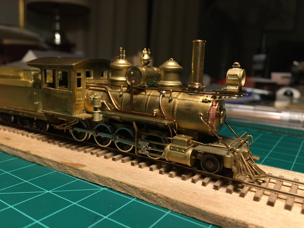 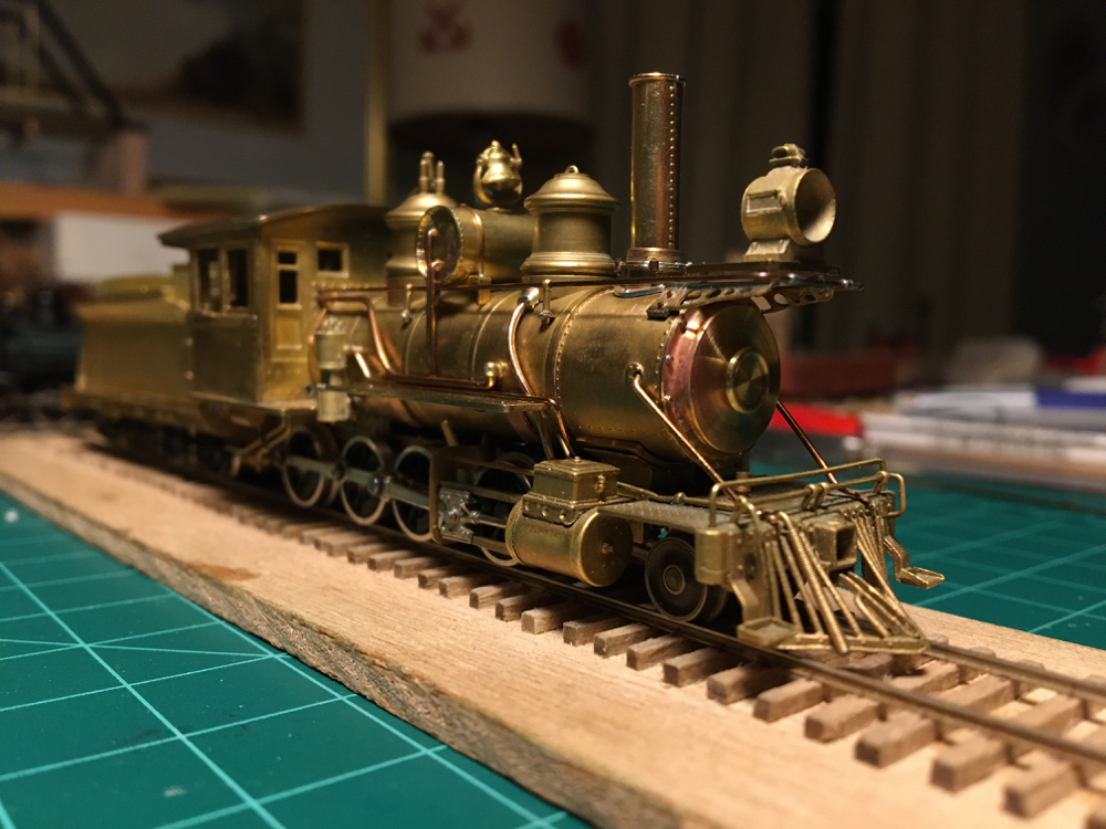 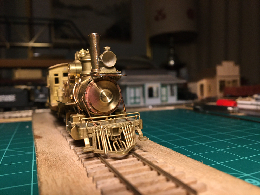 Looks to me that the nuts on the smokebox front mounting studs are too tall, need to file them down a bit. Now I have to figure out how to make the hinges and especially the clamps (dogs?) on the smokebox door. Does anyone know of a good drawing of the clamps? I'm working from photos and though I've looked at very many, I'm still not sure of the exact shape. Of course, in HO scale I won't be able to make them really right in any case, but I'd like to come as close as I can. The major egregious remnant of the C-16 is now the pilot. I'm thinking of making a C&S one out of wood like the real thing. But first I have to remove the pilot deck and since it will now be visible, make a proper frame for the pilot, which the Westside model doesn't have. Cheers, John
John Greenly
Lansing, NY |
|
This post was updated on .
Exquisite work, as always, John.
Good to see you back to work and posting. I've looked at many photos and don't see any sign of a valve or other control on the sand flow. How did these work? Before the pneumatic sanders were installed (about 1912?), the sand flow to the pipes to the rails was controlled mechanically by a lever that ran horizontally thru the entire base of the dome and protruded just a bit from the engineer's side of the dome, just above the sand pipe connecting fitting. The lever was connected via a small diameter rod running back to the cab, to allow the engineer to pull on the rod, to start the flow of sand to the rails. Nothing visible on the fireman's side -- the fireman only got to fill the dome with sand, only the engineer got to empty it!! Problem is, the sand lever and control rod were just about the same height off the rails as the hand rails, and usually are hiding behind the engineer's side hand rail in photos. You can see the lever and rod on this enlargement of rebuilt Cooke number 8 circa 1906: 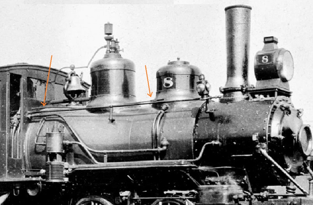 and on number 9 circa 1909: 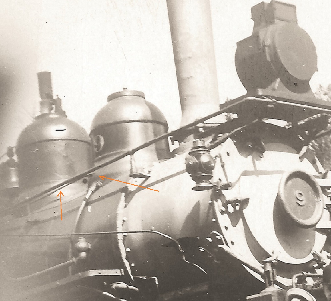 The rings on the early Baldwin and Cooke domes further obscure the little lever/rod. As to the smoke box front door retaining dogs, they look to me like the Euro currency sign. This drawing was posted earlier (by Rick Steele?) and shows the design of the extended smoke box front: 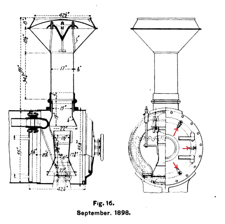 This enlargement of number 9 gives a reasonable look at one of the dogs from the side: 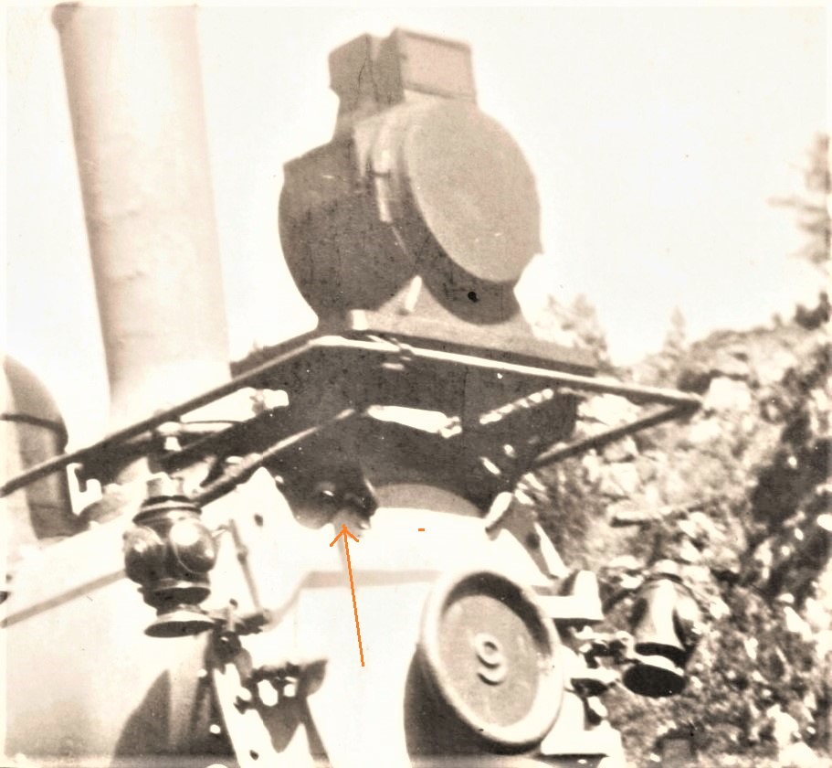 The upper and lower ends of the Euro sign touch the smoke box front and the edge of the door on the extension; the middle lines of the Euro sign is the retaining bolt, running in an angle into the smoke box front extension (does this make sense??) BTW, I'm going to follow your example, albeit in a larger scale. I've rounded up a bunch of Sn3 stuff my friend Dale has use for, and later this week I'll be trading for an old PFM Sn3 C-16. Instead of number 30, I'm shooting for Cooke number 47. 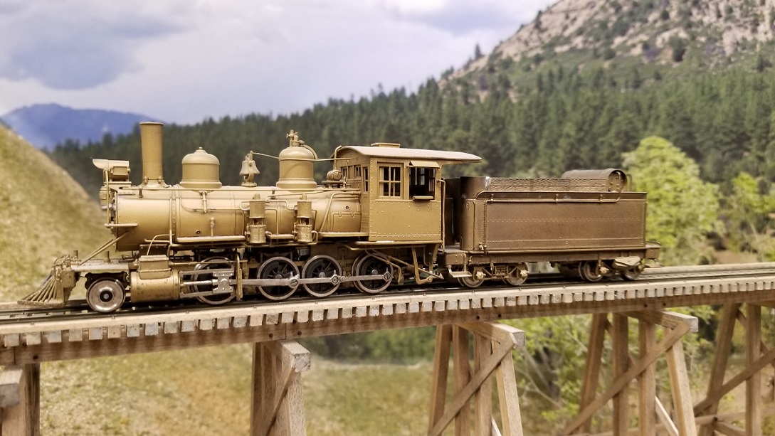
Jim Courtney
Poulsbo, WA |
|
In reply to this post by Rick Steele
Rick,
Is there an error in the Class 56 sheet 6 folio 7 drawing? It shows the driver wheel base as 11’4” and the distance from the lead driver axle to the pony truck axle as 3’9” plus 2’9” for a total of 6’6” when I add those dimensions I get 17’10” not 17’7 1/2”. Have I missed something? Thanks in advance. Lee Gustafson |
|
My math says you're 2 1/2" off !

"Duty above all else except Honor"
|
We do keep telling ya .....metrics are easier, but ya don't listen.  
UpSideDownC
in New Zealand |
|
Chris &South Park,
I’m referring to the drawing at the very top of Rick’s folio drawings labeled D&RG Class 56. The dimensions are 4’1” + 3’2” + 4’1”+ 3’9” + 2’9” =17’10” Not the 17’7 1/2” shown on the drawing. I agree that metrics are easier but I’ve checked this on three different computers. Respectfully submitted. Lee Gustafson |
|
This post was updated on .
Hi Lee, yes! You and your computers are correct. I checked it with the computer I keep somewhere in my forebrain (I think it's there; sometimes it eludes me nowadays).
But I have two other questions about locomotive dimensions that might be of more interest. First is about cab dimensions. I've measured some cabs in photographs with nice straight side views, and I find that cabs are longer, by about 4 or 5 inches, than the dimensions given in folio sheets. For example, #13 is listed as having a cab that is 5' 2" long, but in the well-known photo of #13 with the intertwined lettering, in central City , 1903 (p. 66 of Coleman, Vol. VI, NG pictorial) , by comparing to the driver spacing I get a cab length of 5' 6". Similarly, the photo of #9 (p.46) also with intertwined lettering, ca.1910, gives a cab length of 6' 4", while the folio sheet shows 6' even. The same thing appears to be true with cab width. That's harder to get good measures of in photos, but in a couple of cases where I can get it accurately I find again that the actual width dimension is somewhere around 4-6" bigger than listed. NOTE ADDED: These numbers are not accurate! Complete photo analyses (see below in this thread) show that the outside dimensions of the turn-of-the-century 4-panel cabs and those with added sheet metal on the sides like #13 did agree with the folio dimensions. These were really small cabs!! However, later on (roughly 1910 or later) larger cabs were indeed fitted to many engines. --John My second question is about locomotive boiler diameter. I know well the admonition not to try to measure dimensions from the drawings, they are schematic only, not scale, or even of the same locomotive. But it is true that the folio sheets all show the basic shape of the boiler without lagging, so for instance the forward-most boiler section is shown as being smaller in diameter than the smokebox, and it is this smallest section that has the dimensional marking for the boiler diameter. That would mean that a model, which of course has the fully lagged boiler, will be larger in diameter than the folio dimension. Again, I'd be very grateful for thoughts on this question. Cheers, John By the way, I'm excited that Jim is going to do a C-16 conversion, too! The more the merrier, and I'm sure I'll learn a lot from that project.
John Greenly
Lansing, NY |
«
Return to C&Sng Discussion Forum
|
1 view|%1 views
| Free forum by Nabble | Edit this page |

