C&S #30, a C-16 conversion

1234

1234
Re: C&S #30, a C-16 conversion

|
I believe that scaling from photos would probably be more valuable than reliance on the folio drawings and measurements. Jack Burgess has some information on using Photoshop to measure prototypes from photos on his YouTube videos.
Todd
Sent from my iPhone On Dec 4, 2020, at 8:12 PM, John Greenly [via C&Sng Discussion Forum] <[hidden email]> wrote:
|
Re: C&S #47, an Sn3 C-16 conversion
|
|
In reply to this post by John Greenly
Hi John, thanks for inviting me aboard!
The planned equipment swap with my friend Dale was consummated yesterday afternoon (in his driveway, with masks and social distancing . . .). I came home with a PFM Sn3 C-16. The little guy is a contemporary of John's HOn3 Westside C-16, built in 1976, one of an incredible batch of 600 models. There's a lot of these guys out there, if this first conversion is successful. I got lucky on this swap -- the owner prior to Dale had re-geared the locomotive with a nice Samhongsa 36:1 gearbox and replaced the original open frame motor with a Mishima can motor. It runs very smoothly, almost imperceptibly, a low speeds. While John is doing a conversion to B4-A Baldwin #30, I've always wanted a B4-B Cooke, specifically C&S 47 as in this 1910 photo: 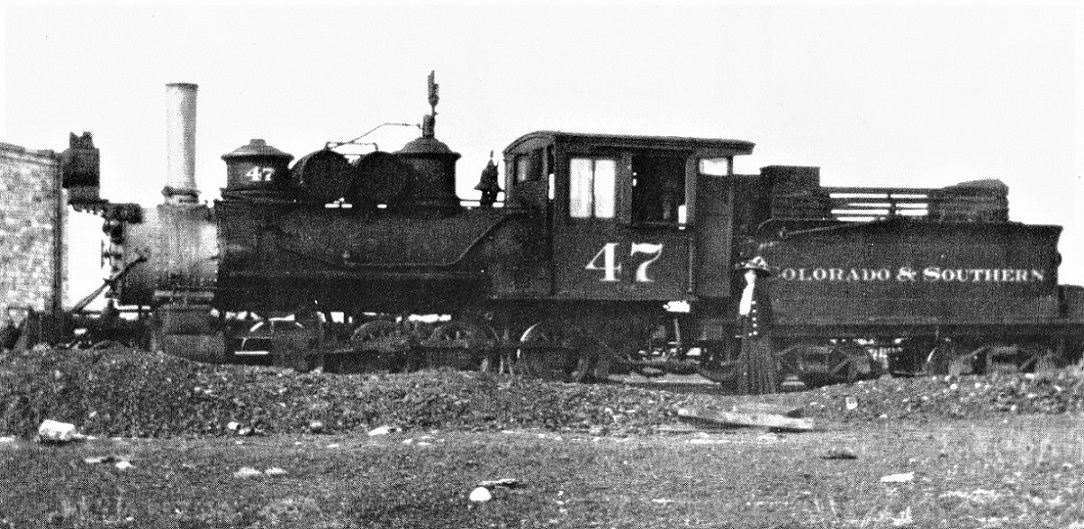 After a day of measuring, trying out various parts in my stash of Sn3 castings, this is what I've accomplished so far: 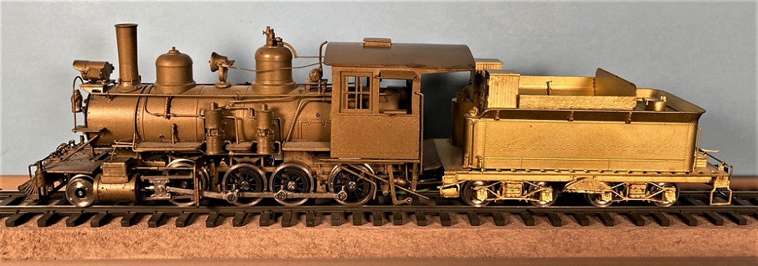 The easiest way to make a C-16 start to resemble a C&S Cooke is to add a Cooke tender! John's musings about the cab dimensions is interesting. The un-rebuilt Cooke 2-6-0s (11-12-13), the rebuilt Brooks (21, 22), the surviving early Baldwin (30) and the Cooke 2-8-0s (37-56) all share the same cab dimensions and for the most part, the same tender dimension, per the folios. The C-16 cab is larger than portrayed in the folio drawings. I have a couple of cabs from Overland 21 and 22 that I planned for the conversion, but that will require either: a) Removing all of the C-16 cab except the front wall, then filing the front wall sides and top to make the cab narrower and a bit shorter. b) Starting over with a new boiler and cab front wall to accommodate the smaller cabs. John's musing about the true cab dimensions raises another possibility: c) Leave the C-16 cab alone and modify the roof overhang, fore and aft, to more resemble the C&S Cooke cab. If John's calculations are correct, then my existing C-16 cab is close, 5'7" long and 8'1" wide. The C&S cabs in the first decade were still wooden cabs with outside steel sheathing on the sides, so the folio cab dimensions may indeed reflect inside dimensions. Hmmm . . . maybe I'll just follow the Greenly method of stripping the boiler and cab of everything that doesn't look C&S, fill the holes and start adding new stuff like correct running boards, pilot, smoke box front, air tanks, etc. I actually did rebuild one of these little guys back in the early 1990s, for my brother, backdating it to a RGS C-16, c1910. So John, could you compare the cab of 47 in the photo with the Cooke wheel bases in the folios, see what you can come up with in terms of calculated cab length and height? In the meantime, if memories from 1992 are correct, the next thing to do on my conversion is to remove the boiler/cab assembly from the mechanism and soak it in lacquer thinner for a couple of weeks, to remove the 40+ year old PFM brass paint and lacquer top coat.
Jim Courtney
Poulsbo, WA |
Re: C&S #47, an Sn3 C-16 conversion
|
|
This post was updated on .
Hi Jim,
#47's cab is bigger than the folio dimensions, like the others I've looked at. It's at least 5' 8" long, and just about 7' height to the top of the roof peak above the top of the floor. The rear roof overhang is about 2'6", and that does agree with the folio. You know, it seems to me that we should acknowledge that those folios were not made with model builders in mind! We generally care only about outside dimensions of things, because that's what we build and see. But what dimensions were of practical interest to the railroad? Certainly the extreme height to the top of the stack, the total wheelbase and overall lengths would be indispensable for clearance considerations on the road, in engine houses, on turntables, etc. The folio's cylinder dimensions, 15x18", are obviously inside dimensions, that's what the railroad needed to know for performance calculations. Likewise, the basic spec for the boiler given to the builder would likely be the actual boiler diameter, not the outside of the lagging, and that bare diameter does appear to be what's indicated on the folio drawings. Similarly, it seems to me that cab inside dimensions would be of practical interest in thinking about how things fit in there. NOTE ADDED: see the posts below. Measurements show that the 4-panel wood cabs in the 1890's-early 1900's time frame did have outside dimensions like the folios. --John Anyway, I can say that based on this photo your model's cab is probably about right, if anything a bit too short. And absolutely not 5' 2.5" as per the folio. Cheers, John
John Greenly
Lansing, NY |
Re: C&S #47, an Sn3 C-16 conversion
|
|
This post was updated on .
Wow, John, just like the "caboose that never was thread", we're discovering things that cast a lot of doubt about past model building/manufacturers decisions, perhaps based on misconceptions about the folio sheets.
Consider the HOn3 Key C&S 22: 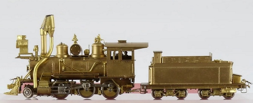 Image from BrassTrains.com I owned one years ago. I always thought that the cab looked small in proportion to the locomotive. Perhaps Key used the folio cab dimensions?? The Overland Sn3 models of C&S 21 and 22 may have the same problems. I'm using the models to build earlier versions for 1901 and 1909 and actually have some extra cabs that I was planning to use on the Cooke 2-8-0s. If your measurements are correct, then I've acquired cabs too small for the planned model. Consider this 1918 portrait of C&S 21: 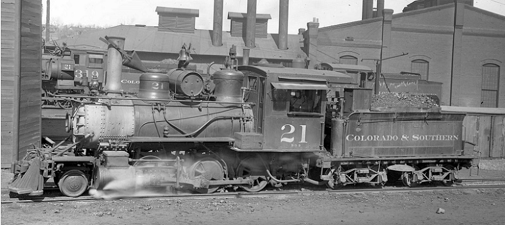 What is your gestimate of cab dimensions from the photos?? The folio sheet shows this cab to have the same dimensions as the Cooke 2-8-0s at 5 foot, 2 1/2 inches long. Comparing the models to the photos, the model cabs seem small in relationship to the tender. The Overland first run C&S 22 in Sn3 has a cab that is noticeably larger than the later offerings--maybe it is correct after all, derrived from photos, not the folios. I will have to dig it out and measure it. As for the folio sheets, one would think that the cab measures would be outside dimensions, for the clearance reasons that you have mentioned. Maybe the interior volume of the cab was in some way more important. I'm sure glad you started this thread. I've always wanted a couple of Cooke 2-8-0s, but it never occurred to me to modify a C-16! My project is still on pause as the lacquer thinner works its magic on that stubborn PFM paint. 
Jim Courtney
Poulsbo, WA |
Re: C&S #47, an Sn3 C-16 conversion
|
|
This post was updated on .
Jim, I measure this model photo right on 5' 2.5", the folio dimension. The cab in the photo is at least 5'8" long.
The difference between the model and the photo is quite apparent by eye to me. Just look at the proportion of cab side height to length. The difference between 5' 2" and 5" 8" changes the proportion of that rectangle quite a lot. This isn't the first time I've noticed these discrepancies- it's bothered me for a long time. It's the same with my old PFM mogul, the cab length is 5"2", and all the photos of the relevant engines have always looked to me like they have longer cabs. I had assumed that they had all been lengthened at some date after the folios were done. But when I started on my backdating project for my #13 I began to wonder whether the wood cabs with sheet metal on the sides were longer as well. I need to go back and measure! Well, and how about cab width? Yes, I agree as to the folios, I certainly would have thought that the extreme width of the cab would need to be given for clearance reasons, that's the widest part of the engine. From Rick's data, The D&RG width of 8' 6.5" must indeed be the extreme width of the cab roof overhangs, which is what the Westside model is, while the actual outside width of the cab sides is 8' 2". The C&S engine is listed as 7' 10". This is what the PFM model is in outside width, and it's almost ridiculously narrow- the doors on narrow gauge cabs are never very wide, but that width forces the front cab doors on the model to be barely over 12" wide, how could people get through them? And how could they possibly get through inside the cab to that door past all the gear in there, anyway? On the Westside model, and presumably the real C-16, those doors are wider, 15-16". John
John Greenly
Lansing, NY |
|
|
Why not compare the Folio measurements with existent locomotives.
|
Re: C&S #47, an Sn3 C-16 conversion
|
|
Yes, I wish someone would do that! I'm here in NY state, sadly no C&S engines handy!
John
John Greenly
Lansing, NY |
|
|
Well I was going over to Silver Plume but that got cancelled, next time I am on Breck will oblige.
|
Re: C&S #47, an Sn3 C-16 conversion
|
|
This post was updated on .
In reply to this post by John Greenly
OK, John, I've been perseverating about these apparent inside cab dimensions on the folio sheets. Just doesn't make sense to me that they would be recorded that way. So, let's try out this thought:
The C&S locomotive folios supposedly were drawn up c.1899-1903, at the beginning of the new company. The fact that most of the locomotive diagrams have McConnell stacks is consistent. So what if the cab dimensions are truly outside dimensions, but only at that point in time. The folios might even have been inherited from the receiver or an even earlier UP record, and merely relabeled as C&S folios. In other words, were C&S cabs smaller in 1900 than say 1910 or 1918 or 1930? Case in point is C&S 22 at about 1900, posed on the Como turntable: 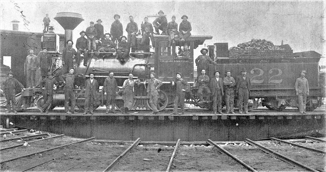 In Kindig, et al., Pictorial Supplement . . . I chose this right angle view because I'm not good at that perspective stuff. Per the folio sheet for C&S 22, the cab length was 5'-3", drivers are 37" in diameter. By my amateur measure and use of simple proportion, I come up with a 1900 cab length of about 5'-5", close to the folio. I get a calculated cab height (top of floor to peak of roof curvature) of 6'-7". The 22 folio has no cab height inked in, but the two dimensions are close to those of the Cooke 2-8-0 folio cab dimensions (5'-2.5" and 6'-7.5"). Prior to 1899, number 22 was numbered 162 on the DL&G. I tried cab calculations with a bit of perspective with this view, sometime after the 1894 boiler rebuild: 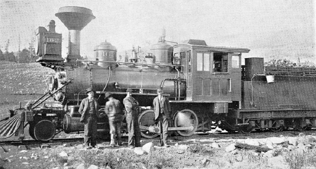 My uncertain math comes up with a cab length of 5' - 3.8", again very close to the folio. I had difficulty in the vertical measure of the cab height but I get 6' - 5" to 7". I had always assumed that the original wooden cabs were merely steel sheathed beginning about 1902-1906, but it is quite possible that the cabs were new construction, becoming longer, taller and wider with subsequent shopping and rebuilding. That would explain the discrepancy between the folio dimensions and the observed dimensions in photos 10 to 20 years later. So, measuring existent locomotives wouldn't reconcile with the folio sheets Does this explain why model manufactures made the cabs undersized, seeking accuracy from the only printed records, not recognizing the difference that occurred over time? Please check my work, John--as McCoy would say, "I'm a doctor, not an engineer". And while you're at it, please give me your best estimate of the cab length and height from this earlier view of C&S 21. 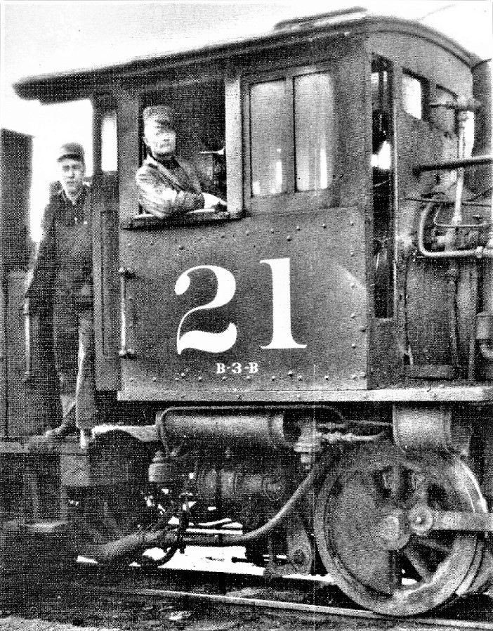 I believe this is the original wood cab with simple steel sheathing applied, sometime between the new lettering (1906) and the closing of the Highline (1911). Note the cab still has the clerestory on top, like C&S 22 above. To me, this cab looks smaller in length and height than the all steel cab in the 1918 Otto Perry photo of number 21 above. Thanks, Jim
Jim Courtney
Poulsbo, WA |
Re: C&S #47, an Sn3 C-16 conversion
|
|
In reply to this post by Jim Courtney
Jim
I've used acetone to de-laquer brass models. Longest time to work as I remember was overnight, though usually several hours. Pat |
Re: C&S #47, an Sn3 C-16 conversion
|
|
In reply to this post by Jim Courtney
Jim,
In the cab view of #21 do we know the dimensions of the cab number and can we use that to estimate the cab dimensions? Some where I thought there was a standard for C&S lettering. Maybe a long shot. Lee Gustafson |
Re: C&S #47, an Sn3 C-16 conversion
|
|
Good point, Lee,
Hol Wagner, in his book The Colorado Road, states that the new lettering scheme, adopted in May of 1906, specified cab numerals that were 18" tall. I'll defer to John, but I suspect that helps us with estimating vertical dimensions, but not the horizontal dimensions in perspective, like the length of the cab. I hope that the 37' diameter driver, just below the cab, would help estimate all dimensions.
Jim Courtney
Poulsbo, WA |
Re: C&S #47, an Sn3 C-16 conversion
|
|
This post was updated on .
In reply to this post by Jim Courtney
Okay, here we go.
I apologize for the delay in responding, Jim. I hadn't done my full hand-calculated analysis of these cabs, the way I did, for instance, for the cabooses. With the cabs a difference of 4" or so is relatively small, only 6%, and I really shouldn't have made a statement about those without doing the full analysis. This was getting to be a big job to do the full work for all of them, so I decided to finally take the plunge and get the computer into it. After some research I settled on the Sketchup software package to do what I did before by hand. I got the software and first tried it out on photos of my models, so I knew the real dimensions perfectly well. Once I figured out how, it did an excellent job with those, correct within 1 scale inch or better, so then I went on to the photos in our thread here. I've now done all of them, and here are the results, in the order the photos appear above in the thread. the photo of #47 in 1910: cab length 6'2", height 6'7" top of floor to upper edge of roof, (not to the peak as before, that's not reliable with the software). So that is indeed a much bigger cab than the folio had, even bigger than I had estimated earlier. the photo of #21 in 1918: cab length 5'11", height 6'10" to roof edge, again, no relation to the folio, and even bigger than my earlier result. now to the earlier wood 4-panel side cabs, first the photo of #22 on the turntable: cab length 5'2", height 6' to top edge. --folio, OK! the photo of DL&G 162 (C&S 22) with certainly the same cab: cab length 5'2", height 6'. --folio, yes. and then, two with the sheet metal riveted to the sides: the closeup photo of #21 in 1909, cab length 5'2", height 6'0". --folio yes. And finally, the photo I referred to above of #13 at Central City in 1903, length 5'2", height 6'0'. --folio, yes. So, my summary at present is that the earlier four-panel cabs, which were not original to the South Park engines but were standard by the 1890's, (maybe a UP thing?) were the ones that the folios measured as I had originally assumed and Jim also suggested. At least some, probably many, of those 4-panel cabs received the sheet metal covering that #13 and # 21 show in our photos, with overall dimensions unchanged. But then at some later time larger cabs showed up. The big cab on #21 in 1918 certainly doesn't bear any resemblance to the old 4-panel. The real puzzler of this bunch is the photo of #47. That cab, other than appearing to be much longer, looks like it could have been the old 4-panel with sheet metal. But no, it can't be, it really is much longer. So, forget about my speculation about inside dimensions, I should have stayed with my first assumption that the cabs had been changed after the folios. I guess I'll go back and caveat my posts above to avoid taking future readers down that wrong speculative path. Meanwhile, I'll give you an example of how I'm doing these, here's the Sketchup analysis of the photo of #21, to show you how it looks when done: 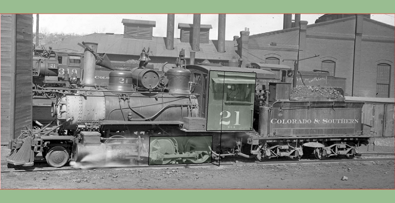 This is done by fitting a 3D axis system to the photo. That's done by hand using the software, by the operator (me). You start by finding a pair of parallel lines in each of two orthogonal directions on the object. The software uses these to determine the vanishing point of the image and thus the position of the camera with respect to the objects in the photo, and this then defines the 3D axes that you can then orient drawn lines to. The computer does those calculations for me instead of me doing them by hand, and that saves a huge amount of time. Thus the black overlaid lines you see on the photo are not oriented to the flat photo, but to those 3D axes that have been defined. So, in particular, that short oblique line segment linking the rectangle around the drivers to the vertical line up to the cab lies parallel to the horizontal axis perpendicular to the rail. That line is 2' long, which is the approximate distance along that axis from the plane of the face of the drivers to the plane of the side of the cab. The cab side plane is closer to you than the driver plane, so to scale from the known wheelbase dimension to the side dimension you must include this offset. The sensitivity of the result to this length doesn't require it to be exact, but it definitely can't be neglected to get results to within an inch. Real care is needed in accurately aligning the axes, and I found that several iterations were often needed to get the two rectangles around drivers and cab to conform exactly to their respective subjects. Having done this several times now I've gotten a feel for how good this needs to be for accurate scaling from the wheelbase to the cab. It is much better to use as much of the wheelbase as possible rather than a single driver, for an accurate result. This is still not a trivial thing to do, but it is MUCH faster than doing it by hand!!! To do this with buildings or other simpler shapes with mostly plane surfaces and right angles, the computer can choose the edges and define lines by itself, and speed up the process still more. It's a very nice tool. I spend way too much of my life with computers and I was resisting doing this, but now I'm very glad I did, I'm happy to have it. Cheers, John oh, and by the way, the cab letters do measure 18" tall.
John Greenly
Lansing, NY |
Re: C&S #47, an Sn3 C-16 conversion
|
|
Strewth, could I have used that technique 30 years ago.
UpSideDownC
in New Zealand |
Re: C&S #47, an Sn3 C-16 conversion
|
|
In reply to this post by John Greenly
John, what a fantastic analysis!
Great news for me, as my extra Overland cabs from the C&S 21 will be of use with the 1909 versions of 21 and 22. And I have some etching sets for the UP 4-panel wood cabs for the 1901 version of 22, perhaps an un-rebuilt Cooke 11-12-13. Since the Cooke rebuilds of 2-6-0s (4 through 10) was one of the first orders of business for the new railroad, between the summer of 1900 and the summer of 1902, perhaps these new larger cabs were the models of cabs that gradually replaced the original wood panel cabs in the first decade. Now I'm obsessed with looking at cabs, the wood paneled ones, the ones that got early steel sheathing below the cab windows and later, larger cabs of steel construction. The early cabs had roofs that sat atop 2 end and 2 sides, like on 22 and 21. the later steel cabs often appear to have roofs that were continuous with the sides, or were the roof/side joints welded? Other first decade new steel cabs: 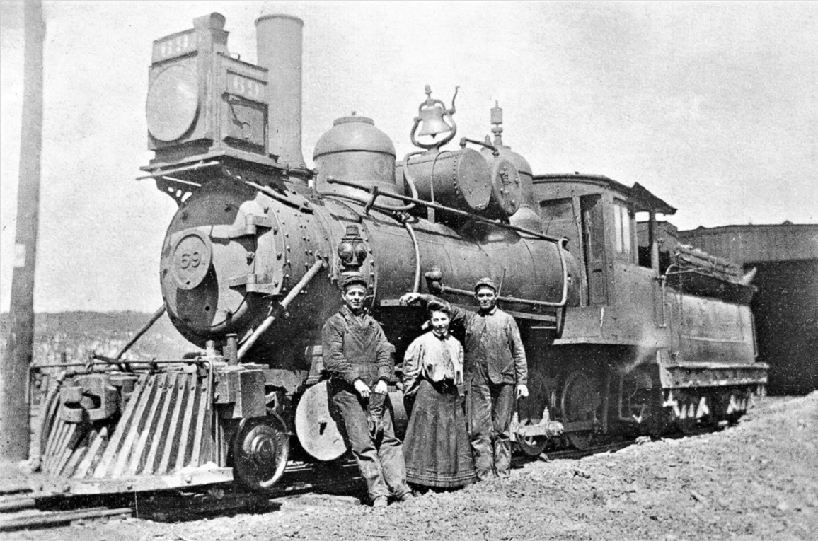 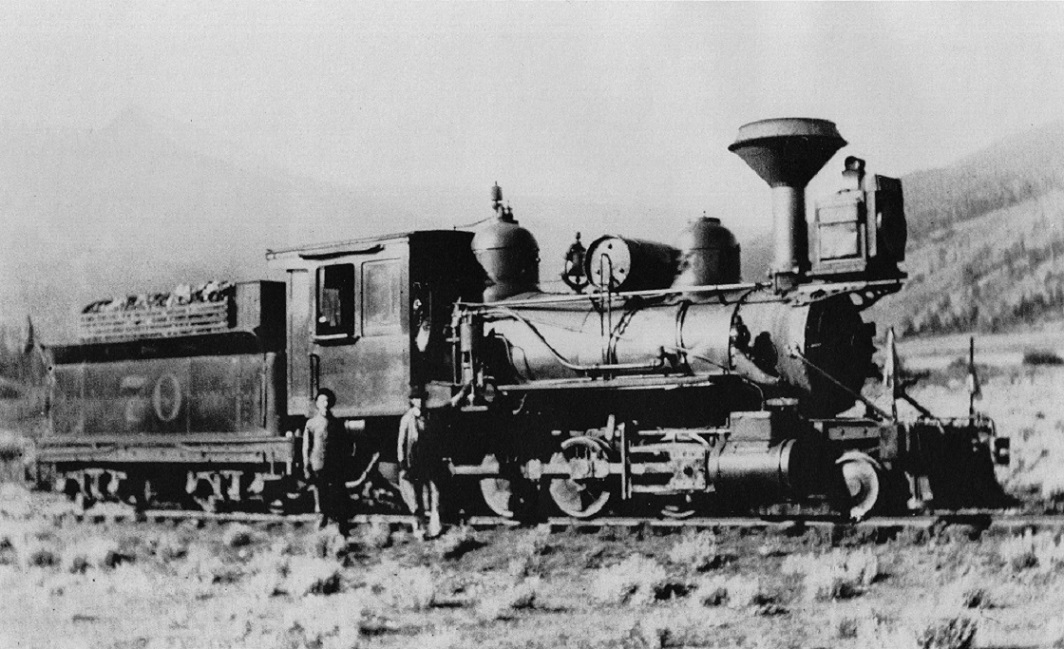  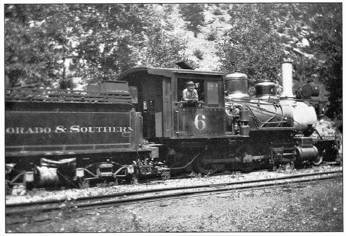 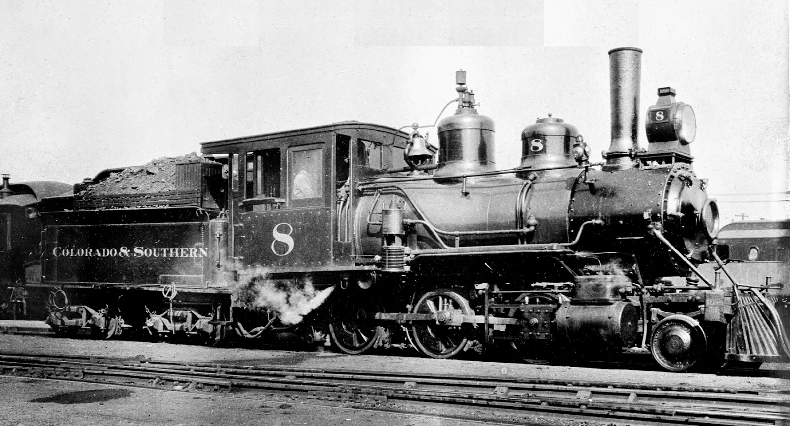 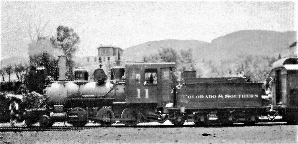   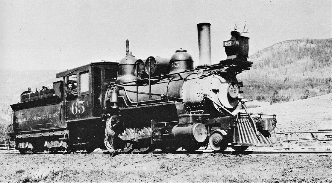   Seems like the cabs that acquired the modern 3-pane window were of all steel construction. Can't always tell whether the 2-pane cabs went through a stage of steel sheathing first then all steel construction or not. Is the cab on number 8 above wood with steel sheathing, or steel throughout. It has to be a new cab built in 1901, when the Cooke was rebuilt. Thoughts??
Jim Courtney
Poulsbo, WA |
Re: C&S #47, an Sn3 C-16 conversion
|
|
This post was updated on .
Jim,
The cab on #8 in the 1908 photo above is about 6' 2" long, about 6' 6" high to roof top edge, and about 8'6" wide. I say "about" for those measurements because this photo is somewhat distorted and introduces an uncertainty of 2" or so in the dimensions. So, this cab appears very much like the cab in the #47 photo, both in dimensions ( though I couldn't get a good measure of width for #47, the view is too nearly side-on), and in construction: particularly, on both, the roof edges and windows look very much like the older wood cabs. So, as you wonder, so do I: what are these cabs made of? If, as appears likely, they're wood with metal sheathing, then that means there were at least two sizes in service around the turn of the century, the very common 5"2" long ones and these 6' - 6'2" ones. If that's true, then the later cabs with flush formed roof edges must have been total replacements, since those are surely all-steel. The story I have read in various places about the roof edges being simply trimmed off flush to produce the modern cabs would be incorrect. By the way, all this is bad news for my projects. The C-16 cab is too big for my #30, which I've now measured to have had the 5'2" cab in the 1910 photos. Also, I discovered why the 5'2" cab on the PFM #13 looks so ridiculously narrow-- that's because it is! I never measured the width before, naively assuming that since they got the length and height right, the width would be too. Nope, that model cab is only 7'6" wide, not 7'10", and that's why the front doors look so silly (narrow!), as I had mentioned in a previous post. Bah! oh well, John Oh- and by the way, my earlier question about the boiler diameter spec on the folios is answered. I was right about that one, the actual outside diameter of the lagged and sheathed boilers is larger than the folio dimension, typically by 4-6". The folio dimension must indeed be the bare boiler diameter. Thankfully, both my models are good on that one!
John Greenly
Lansing, NY |
Re: C&S #47, an Sn3 C-16 conversion
|
|
Jim, I have an On3 number 5 that I could take some measurements of the cab outside dimensions if you are interested...
Todd
Sent from my iPhone On Dec 11, 2020, at 3:57 PM, John Greenly [via C&Sng Discussion Forum] <[hidden email]> wrote:
|
Re: C&S #47, an Sn3 C-16 conversion
|
|
This post was updated on .
In reply to this post by John Greenly
John, welcome to the world of SketchUp!. I am by no means an expert and miss the old 2-dimensional days of AutoCad and drawing with sticks (as I used to call it). A word of caution--one needs to take great care with SketchUp! and the plane you are drawing in. It is really easy to draw a line along a vector out in space you did not intend. Maybe it is the way our office sets it up, but the dimensions can get wonky sometimes. But...you found an interesting use for it. As you state, using larger dimensions to scale should yield better results than smaller dimensions.
Regarding my experience with folio sheets, as a kid, I dismissed them as nothing more than a vague schematic or diagram of the vehicle. During the years I volunteered at work sessions with the Friends of the Cumbres and Toltec, I took on the job leading a team reconstructing the end platforms of former D&RGW RPO 053. Before we took it apart, we measured the car thoroughly, and I found the folios to be pretty darn accurate drawings of the vehicle. More to the point, they are what the car shop would need to order the materials and help the carpenters put the car back together. Now...I discovered my calling to be that of a carman: no boiler shops or machining for me! So I don't know how the folios rate for locomotives. There seems to be general trust in wheelbase and driver dimensions, weights, boiler pressure and so forth. Based on John's observations above, it appears that the locomotive folios are also accurate and represent dimensions that are a concern to the shop forces. One last comment: if you have A Century Plus Ten by Dr. Sloan, he devotes some space to recognizing the D&RGW folio draftsmen by name. Dr. Sloan has been collecting the material for this book for decades and I think it notable that he developed a virtual relationship with these folks as he worked with the source material. With respect to dimensions, I tend to be more in the Allen McClelland "good enough" camp. If my math is right, 1" in 1/64 is a mil; 2" is a 2.6 mils and 3" is 4 mils. To my eye 4 mils is large enough to make a difference, but I probably would not see a dimension discrepancy less than 2" in Sn3. But that is me, and you are the CMO of your model railroad. Jim, thanks for gathering all the locomotive images. Probably should be a new list as this blog is becoming quite the collection of flotsom and jetsam and when the day arrives that I need a cab dimension I will likely forget the pictures are embedded in a string on C-16s!  I have to ask where the pic of 11 was taken? The house on the hill is...unusual. My guess is Idaho Springs, possibly Morrison. Maybe Pine Grove? We seem to be on the north side of the loco looking south. The ridge line beyond seems more like the foothills than the deeper ranges. I have not pieced together locomotive assignments. The number 11-plus Moguls strike me as Clear Creek, Morrison or Fish Train power. Maybe this is at Grants or Shawnee? I have to ask where the pic of 11 was taken? The house on the hill is...unusual. My guess is Idaho Springs, possibly Morrison. Maybe Pine Grove? We seem to be on the north side of the loco looking south. The ridge line beyond seems more like the foothills than the deeper ranges. I have not pieced together locomotive assignments. The number 11-plus Moguls strike me as Clear Creek, Morrison or Fish Train power. Maybe this is at Grants or Shawnee?
Keith Hayes
Leadville in Sn3 |
Re: C&S #47, an Sn3 C-16 conversion
|
|
John,
In S scale an inch is 1/64 or 0.015”. A mm is about 0.040” or closer to 3 to 3 inches in S scale. So 2 inches is about 1/32nd inch or .8mm.
Todd Sent from my iPhone On Dec 12, 2020, at 12:27 PM, Keith Hayes [via C&Sng Discussion Forum] <[hidden email]> wrote:
|
Re: C&S #47, an Sn3 C-16 conversion
|
|
I think we're getting mil and millimeter confused. A mil is .001" which is much less than a millimeter, although some people use mil as a shortened version of millimeter, primarily when speaking, but this can be confusing since both are used to measure thickness, and a mm is almost 40 mils. I hear this all the time with wetsuits, which are classified by neoprene thickness in mm, but what is printed on the label as 3mm is often spoken as "3 mil." In S scale one scale inch is 1/64th of an inch, which is .0156" or 15.6 mils or 0.4 mm. Three scale inches would be three time that, so .0469", 46.9 mils, or 1.19 mm. To get an idea of just how small a mil is, human hair and paper are typically a few mils thick. |
«
Return to C&Sng Discussion Forum
|
1 view|%1 views
| Free forum by Nabble | Edit this page |