the caboose that never was
1 ...
34567


1 ...
34567
Re: Short wheel base South Park / C&S cabooses.
|
This post was updated on .
Well, it's been simmering for a long time, and now I've taken the plunge, thrown caution to the winds, got up steam and gone round the bend.... I found some slightly clearer versions (thanks Bror!!) of a couple of the short-wheelbase caboose photos we have posted in this thread (I'll put them up here in a following post). After a lot of considering I finally came to (I hope) a good enough idea of what the short wheelbase undercarriage looked like and how it worked, to be worth building a model of caboose 313 as in the 1910 Blackhawk photo. There are things visible in photos that I have not yet put on the model. I have included only parts whose configuration and function I can presently make sense of. Here's the model at present:
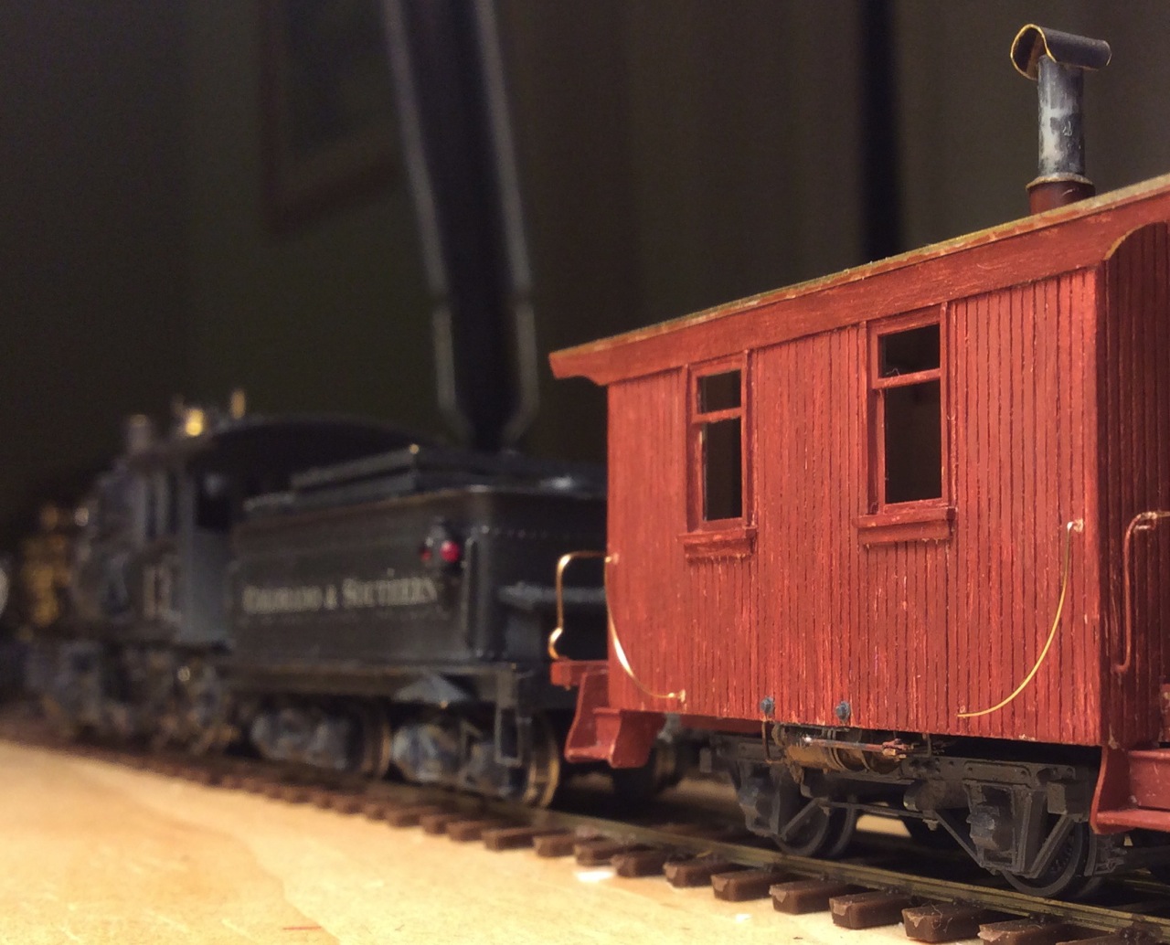 I decided to do this, first, in order to have an actual model of my hypothetical undercarriage that I can compare closely with all the photographic evidence, to check my calculations from the photos and to see exactly what should be visible from various perspectives. Second, constructing the model lets me see whether things would fit together properly to work correctly. The requirement that it actually works constrains speculation about what it should look like. Certainly many or most of the details are wrong, but I believe that the wheelbase (6"4") is correct, and that the journals were carried in pedestals mounted on a beam in a configuration typical of passenger car trucks, with outside brake beams and standard brake rigging. I've chosen the dimensions using all available photographic data. The position of the brake cylinder visible in the Black Hawk photo is copied on the model, and it fits naturally to this rigging: 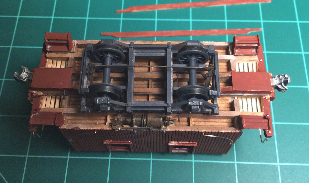 I used Derrell Poole's drawings of the original South Park waycars, the folios, and the available photos, for dimensions and details of the rest of the car. I originally thought I'd use a Grandt caboose kit, but quickly realized that not only the undercarriage, but the sides, ends, end beams, draft gear mounting, roof, and pretty much everything except the sills and basic framing are different than on the Grandt model of the rebuilt caboose 1005. So the only Grandt caboose parts I used were modified steps, along with heavily modified Grandt passenger car windows and doors, and most of the parts of a Grandt passenger truck. I thought I'd make 313 in quite run-down condition after nearly 30 years of life without rebuild except for the air brakes and couplers. By 1910 it apparently had been demoted to work train duty, as seen at the Black Hawk flood cleanup, and it was destined for the scrapyard only five years later. I built the body of wood, painted it rather heavily with off-white as it might have been in its early days, then overpainted it red and wore a lot of that off again. I'm not sure I'm done with it yet, so I haven't permanently attached the handrails or roof. And of course it needs lettering. 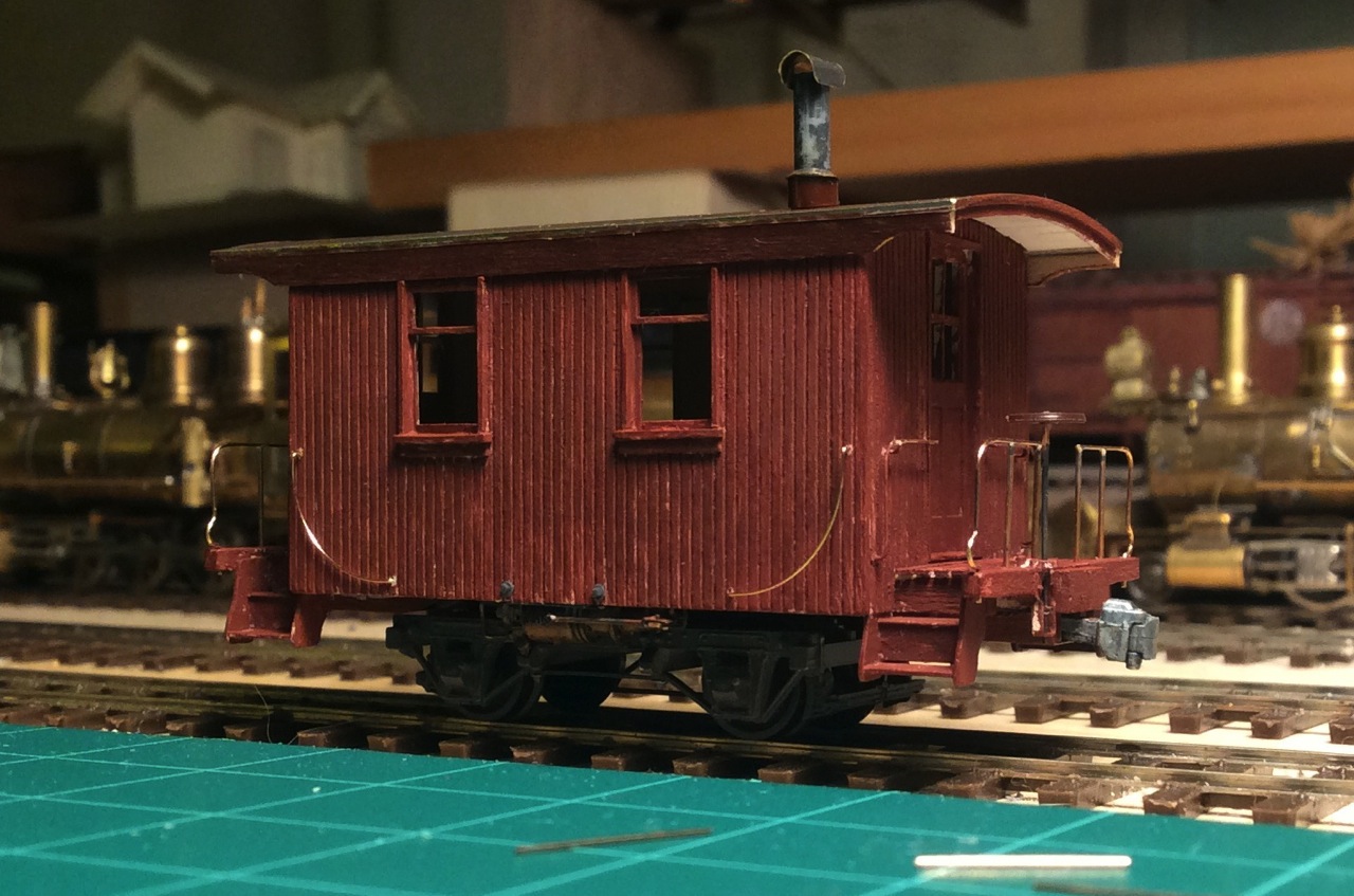 I said way back in this thread that my models of cabooses that never were hasn't discouraged me, that I actually really like the stories of mistakes and uncertainty that they tell. This is in some ways the most uncertain yet, but I hope it at least might give us a starting point toward figuring out what the early short-wheelbase cabooses really were like. 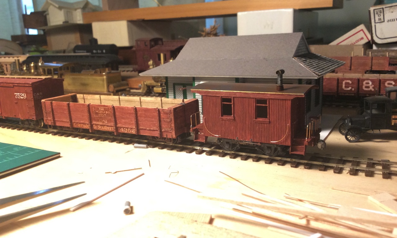 By the way, this car trundles along behind a train just fine, it doesn't seem any more prone to leaving the rails than the 9' wheelbase cars. And this one's rather top-heavy, having a brass roof on a wooden body with mostly plastic undercarriage. John
John Greenly
Lansing, NY |
Re: Short wheel base South Park / C&S cabooses.
|
Administrator
|
Super nice work, John!
|
Re: Short wheel base South Park / C&S cabooses.
|
Thanks Mike!
I hope maybe this weekend I'll have some time to take some good pictures of my model from the correct perspectives to make comparisons with the photographs that we have of the real cars. That will be the best way to explain why I made it the way I did, and to see what might be right about it and what's definitely wrong or missing. Cheers, John
John Greenly
Lansing, NY |
Re: Short wheel base South Park / C&S cabooses.
|
This post was updated on .
In reply to this post by John Greenly
FANTASTIC, John!
An incredible feat of scale engineering and model building. I've spent some time comparing the Blackhawk photo with your model. Most of the things that you have interpreted seem to match what little is visible in the prototype photo. Your work tends to vindicate your theory that the original South Park underframes were simply modified passenger trucks. When you get to your best approximation / concept of the original underframe design, please try to give us some scale drawings if you can. If you're CAD literate, CAD drawings would be great. Perhaps then some of our resident 3-D artists can come up with a Shapeways print in different scales for your historic approximation. And please share your construction details of the underframe. If you built it by modifying a Grandt Jackson & Sharp 5-foot wheel base passenger truck, then I could do the same with one of PBL's Sn3 passenger truck kits (are the Grandt trucks styrene or Delrin?). _______________________ Your post inspired me to go back and critically re-read this entire thread. I'm a bit embarrassed by all the conjecture that I've put out here (a polite way of saying, pulling things out my *ss), yet so far things seem to fit together, suggesting the original South Park caboose underframe was a short 6' 3-4". Just another thought. How is your theoretic early caboose underframe equalized? It looks pretty rigid. I keep remembering the information on the Folio Sheet for caboose 304/1003, stating "type of truck -- swing beam" and "type of bolster -- wood". It sure is consistent with your concept of a caboose plopped onto a passenger car truck c.1880. Did it occur to you that your original truck / undercarriage might have actually been able to pivot at the center of the car? The original caboose bodies were over 17 feet long over the end beams, riding on an undercarriage about 1/3 of the length. The ability of the underframe to pivot around the car center-line, when being pulled, would make the car less prone to derailing, wouldn't it? Probably not when being pushed, but all those photos show rear helper locomotives always cut in ahead of the caboose.
Jim Courtney
Poulsbo, WA |
Re: Short wheel base South Park / C&S cabooses.
|
This post was updated on .
Hi Jim,
I'm very glad you're rejoining this thread! I'll try to give a couple of thoughts on your points, more detail to come when I have more time. First, yes, I think it's a good idea to set as a goal the production of drawings that could generate 3D printed parts. I'll try to do that when we all come to agree on a picture that embodies everything we can reasonably get out of the available imagery. I did use a Grandt 5' wheelbase truck, and I'll put up some photos I made that show how I took what I needed from it. I see that you've of course gone straight to the heart of the questions that I want to define and discuss with this model I made: How was this truck- let's go ahead and call it that- attached to the car body? You see, in the underside view I posted, a big empty space in the middle of the truck where the bolster should be. The truck is simply rigidly attached with crossbeams at each side of that central space, locating the truck beams suitably below the sills at a position to match the photos and put the car body at the correct height above the rails. The springing is by coil springs in the pedestals, just like the later long-wheelbase (9') undercarriage; the only difference is that the truck beam is lower to the track, so the pedestals are lower as well and there is less vertical travel available for the journals. My model doesn't actually have springs in it, but there is the space above the journals in the pedestals where the springs would be. Now we come back to the folio description: swing beam truck, wood bolster. What to make of that, indeed? First of all, I did consider actually using a pivoting bolster like a standard truck. After long thought I rejected that. I really don't think it would do anything good. It would be needlessly complicated, the car would tip more and jolt uncomfortably when it came onto the side bearings, the truck would come off when the car derailed, it would need more maintenance and would as you suggest be likely to cause problems when the car is pushed- when the train backs up. On a curve, the coupler would push the car body sideways, and it would likely end up "skew-hawed", as an old friend of mine likes to say. I can say that in use my model tracks fine with the non-pivoting truck, both when pushed and when pulled. Despite the long overhang from wheel to coupler, the short overall length of the caboose results in a geometry that keeps the couplers quite well centered on a curve when it is hitched to a freight car or tender, and the wheels don't get forced over to flange-on-railhead screeching (can that be heard in HO scale??). However, I can't claim to absolutely rule out a pivoted bolster. Now we maybe need to talk a little about truck evolution, in case any readers have not studied it. In the very beginning of railroading, people thought trains would not have to be sprung at all, the beautiful smooth rails would give a perfect gliding ride! Very soon railroaders were disabused of this notion, and pedestals with individually sprung journals were introduced. That's what my model has, and that's what the rebuilt modern C&S cabooses had. As cars began to have two four-wheel trucks, these had to pivot to follow the curves and so the pivoting bolster appeared. This truck bolster was a rigid crossbeam attached to the truck sidebeams, all of wood, and the crossbeam had a pivot bearing in its middle, carrying the car on a body bolster crossbeam mounted under the sills. The next huge innovation was the swing-beam truck. This was invented to mitigate the problem of sudden sideways lurches due to uneven track that brought wheel flanges violently against the railheads. The truck bolster was no longer rigidly attached to the truck beams but instead floated freely with some sideways play, and the load was transferred from it to the truck by springs located between this floating bolster and a "spring plank" below it that hung by links from the truck crossbeams. This sprung sideways free play absorbed the sidethrusts and greatly eased the ride. This springing of the bolster gave added vertical compliance to the whole truck as well. By the time our cabooses were built this had long been universal on passenger cars (it took longer to be widely adopted in freight trucks). I have not built this into my caboose model, but I think it is likely that some version of it probably occupied that space in the middle of the truck. I'll point out the (sadly, extemely scant) photo evidence for that later. I can say that it could not have been the version with transverse leaf springs that was already standard on passenger cars, because these would certainly have been visible in the 313 Blackhawk photo. I'll come back to this question in a further post. I have a lot of further thoughts about it. It's the thing that bothers me most about what I've made. Unfortunately, we may never know what was really there, because that structure would be rather well hidden from an outside view. The last big innovation in trucks was equalization. In the typical passenger truck, from the 1870's and for a hundred years following, this was done by an equalizer bar bearing downward on the tops of both journals on each side of the truck, with the springs relocated from the pedestals to inboard positions on this equalizer bar. These are the coil springs seen on each side of the center leaf springs on a typical passenger truck. This accomplished the function of distributing the load as individual wheels bumped up and down. It had been standard for quite a while on locomotives before it was applied to trucks for rolling stock. My model does not have equalization because it is clearly not present in the 313 Black Hawk photo. It would certainly be visible. By the way, there is a huge amount of excellent information, drawings and photos of all this evolution in a pair of books, The American Railroad Passenger Car, and The American Railroad Freight Car, both by John H White, Jr. These are both 600+ page behemoths packed full of the entire fascinating history of rolling stock. Bedtime reading for years to come.... One final observation for now. I have not found evidence of any 3 foot gauge passenger trucks with a wheelbase as long as 6'4" in existence when our cabooses were built in the early 1880's (I'd love to know if I'm wrong about that). In any case, if there had been any they almost certainly would have been equalized, which our caboose trucks aren't. I believe that pedestals, springs and journals made for passenger trucks were mounted on new, longer wood beams to make our caboose trucks. These would have been the most common and readily available individually sprung suspension components at that time. Why, then, was 6'4" chosen for the caboose wheelbase? A question for another time. John
John Greenly
Lansing, NY |
Re: Short wheel base South Park / C&S cabooses.
|
Beautiful work.
The narrow gauge Pullman sleepers had 6 ft. Wheel base trucks.
Sent from my iPhone
|
Re: Short wheel base South Park / C&S cabooses.
|
Robert, thanks!
Yes, South Park Pullman sleepers were listed as having 6 ft wheelbase trucks. I remember being frustrated in trying to find a photo showing the details of those trucks on cars before about 1880. Photographers always seem to have been too lazy to set up proper lighting to show off the glories of the undercarriages.... I assume the Pullman trucks were equalized, but I don't know. Later photos of the cars all do show the standard type of swing-beam equalized truck, but it's possible that these were not the originals on the earliest cars? In any case, though, it does seem to me that if those had been used on the cabooses, then why would they have bothered to take them all apart to lengthen the wheelbase by 4 inches? It would require a complete rebuild. questions, questions, John
John Greenly
Lansing, NY |
Re: Short wheel base South Park / C&S cabooses.
|
Hi John-
I am not sure why I am getting these message- but they are indeed welcome! First off- equalized or non-equalized- I can't see this functioning for very long. If wheels in trucks are not equalized, the first low spot would put the flange over the top of the rail. Passenger trucks? Probably not. "Design", COPIED from passenger trucks seems more likely. White oak beams, pedestals, pedestal guides, journal boxes that accept equalizer bars- that's a basic truck. A rigid wheelbase works on locomotives because they carry a little weight. A waycar isn't much more than a reinforced chicken coop. Not much weight, even with markers and coal stove added! Even Fairmont trailer cars have springs to keep those flanges in contact with the rails. Of course, we know that the waycars went on to operate without equalization, but that was with a few upgrades (air brake system, automatic couplers) and I am sure the pedestal arrangement had mass in the design. There needs to be some form of equalization, of soon your waycar is being dragged behind the train because it won't stay on the rails. I haven't seen many revealing pictures of the track, either- but from what I have seen, I would not get a handcar going to fast on it. I have seen both square and staggered joints, and I am not certain if either method was standard. Without a back-to-back pair of HUGE ties under the joints on square-jointed track, you get a LOT of bounce. Bounce isn't really a problem as far as equalization is concerned, but the surface must be perfect- and the only "perfect" track I imagine was across steel bridges and inside roundhouses. One more "wrench" I should probably add is the "make-do" and "stop-gap" assemblies needed when a financially strapped railroad still needs a piece of equipment. I have seen two pictures (may be of same loco) that had a temporary pilot fabricated. Who knows what happened to bring this about? Starting with an accident that destroyed/mangled the original pilot, we find the roundhouse foreman filling out an AFE form and crumpling it up and tossing it because he knows it isn't worth the effort. Besides, but the time the response arrives, he has got to wrangle up a bunch of horsepower to take it's place. Not going to happen! Thus we arrive at the shops looking for some steel to weld up for a makeshift pilot. With flash floods, slides and rockfalls, there was probably something waiting to stop the train around every curve. A caboose can wind up in the same boat. Just shove some strings of boxcars around in the middle of the night and you might find you have drug the caboose around for a while, obliterating the undercarriage. Enter the shop foreman. You can just about count the total number of cabooses available on two hands. Neither hand indicates any "spare" cabooses, so you make up what you can. I am certain that on the narrow gauge there were instances that any inspectors knew they had to look the other way- finances, for one- and the fact that the C&S was essentially a branch line. A pint of Ten High whiskey and a wink probably bought some "paperwork"- particularly when the car was to be outfitted later and brought up to scratch proper. There dies seem to be voids in information regarding the roster that experts toil endlessly over, and perhaps they are overlooking the obvious- it was the way it was because it had to be. Period. As far as modeling is concerned- without documentation, I wouldn't get too crazy about modeling a temporary fix on a car. Like the "intermediate" stages of the tenders. How long did those last? They are interesting, I would like to model them, but really- if the shareholders saw scraps of metal tender extensions and the "beaten by local peasantry with sledges" look I imagine the new final appearance was drafted and submitted. Come on! Can you imagine Eastern shareholders coming all the way out to Colorado and seeing the Express from Lower Slobovia waiting to depart? Spring is has been pretending to get sprung out around here, haven't been on the board much lately. I have halted work on #1007, and have the sides cut for #1002, which will probably require another caboose kit to finish- at least I will need to look at the parts and see whether I can use them or not. Interesting end windows, though. I wonder how long it took them to paint WATCH FOR SLACK ACTION above the doors? Cheers! Stan Rutledge -------------------------------------------- On Wed, 2/27/19, John Greenly [via C&Sng Discussion Forum] <[hidden email]> wrote: Subject: Re: Short wheel base South Park / C&S cabooses. To: "snapped_bolt" <[hidden email]> Date: Wednesday, February 27, 2019, 7:53 AM Robert, thanks! Yes, South Park Pullman sleepers were listed as having 6 ft wheelbase trucks. I remember being frustrated in trying to find a photo showing the details of those trucks on cars before about 1880. Photographers always seem to have been too lazy to set up proper lighting to show off the glories of the undercarriages.... I assume the Pullman trucks were equalized, but I don't know. Later photos of the cars all do show the standard type of swing-beam equalized truck, but it's possible that these were not the originals on the earliest cars? In any case, though, it does seem to me that if those had been used on the cabooses, then why would they have bothered to take them all apart to lengthen the wheelbase by 4 inches? It would require a complete rebuild. questions, questions, John If you reply to this email, your message will be added to the discussion below: http://c-sng-discussion-forum.41377.n7.nabble.com/the-caboose-that-never-was-tp8369p13567.html To unsubscribe from the caboose that never was, click here. NAML |
Re: Short wheel base South Park / C&S cabooses.
|
I tend to agree these were not based on actual passenger trucks, but instead both were influenced by equalization technical experience developed over 4 decades of common carrier operation that influenced trucked and non-truck cars. 4 wheel cars are hard riders, so equalization is key, especially on rough track. The D&H had an early caboose that was on display in Oneonta, NY, back in the 1970s (and maybe still is) that has equalization much like that found in the earliest Carbuilder's Dictionary, and I wouldn't be surprised if the UP influence on the narrow gauge lines in Colorado didn't bring this thinking with it to the Denver shops. Carbuilding was a tight-knit community. Waycar/caboose underframes were technical cousins of the passenger truck, but the needs were different as one rode on a bolster and usually carried directly hung brake rigging while the other didn't. I suspect the ride in a South Park caboose on freshly built track on a 10-hour shift was exhausting regardless.
Dave Eggleston
Seattle, WA |
Re: Short wheel base South Park / C&S cabooses.
|
This post was updated on .
Dave and Stan,
thanks for your comments! If I understand you correctly, I think you are agreeing with me that the 313 undercarriage was not simply a standard passenger truck stuck under the car body. Before our discussion proceeds further I would like to make sure we're all using words the same way. Just to clarify the terminology, springing and equalization are not the same thing. For instance, the undercarriage of the rebuilt C&S cabooses had four pedestals that carried four completely independently sprung journals containing the axle bearings. There was no mechanical linkage between the journals. In standard usage, this would be described as sprung but not equalized. Equalization refers to the various systems of coupled springs and levers in trucks, and in locomotives, that distribute the load among all the wheels. I can see no equalizing components in the undercarriage of caboose 313 in the photo at Black Hawk posted above in this thread. I am presuming that there is a spring in each pedestal, though I can't actually see that detail. That's how my model is configured. If that's wrong, if there was no springing there, then either the undercarriage was completely rigid, which would have given a horrible ride to any occupants, or else, I hope, there was springing in the mysterious bolster mounting of the truck to the caboose frame. Unfortunately, we may never know what that was. From the photo I can say only that it was not like typical passenger trucks of the time, which used transverse leaf springs that would show clearly in that photo if they were there. thanks, John by the way, Stan, I'm curious-- what is that message at the bottom of your post? it says: > If you reply to this email, >your message will be added to the discussion below: >http://c-sng-discussion-forum.41377.n7.nabble.com/the-caboose-that-never-was-tp8369p13567.html > To unsubscribe from the caboose that never was, click > here. >NAML Are you getting email notifications of posts here on the discussion forum from some outside source?
John Greenly
Lansing, NY |
Re: Short wheel base South Park / C&S cabooses.
|
Sounds like we are on the same page!
The "individually sprung" pedestals were sprung with leaf springs. In such a small light car, there is little soubt in my mind that SOME equalization between the axles were a result, even though it was not instantly identifiable as "equalized". I suppose the versions with ADDITIONAL bars that are known as "equalized" or "equalizing" were developed as the result of observation during operation and wear markings without said bars. Not sure of exactly which day of the week was chosen to apply equalization to the locomotive itself, but once proven as effective, the idea transferred to several other suspension and truck types. The limiting factor was the economy of such applications. The waycar was probably one of the last places to look for development. Some folks want to believe that the railroads were just in it for the money- but I look at it differently. I believe they wanted a system that was resistant to the ups and downs of the economy and seasonal demands. The waycar or caboose was the most efficient way to conduct business enroute, and the end crew could have clear heads to do paperwork, plan switch jobs and just get home to the barn as efficiently as possible. They managed to do just fine even without being radio equipped. The conductor belongs on the following end of the train. The advantages outweigh the "disadvantages"- especially when there are no survivors on the head end after a serious accident. Let's get back to equalization for a bit. The Fairmont trailer cars have springs. Do the same thing on a caboose, and you have a huge company-branded butter churn particularly if you have square-jointed track. Coil springs don't work well in single-point suspension if you expect a reasonably stable ride. I imagine there were probably at least a half-dozen tried designs before a stable design emerged- and that could be form over 50 unrelated shops! Just some master mechanics squinting under the waycar could come up with at least a few. The first error to be eliminated would be a short wheelbase because of truck hunting. With link and pin, there would be even less resistance to this. Bottom line here is that the C&S managed to keep the "bobber" configuration long after the railroads had left them for the two-truck design. The C&S more than likely perfected this as they continued to repair damaged 4-wheel cabooses without attempting to modify the design. A short wheelbase caboose of the size the C&S narrow gauge would have ACTIVELY RESISTED having trucks installed, especially after air brakes were added. Even if one managed to force a pair of trucks underneath, they would have like to jump the rails if they had any serious pushing on the end. With the combined slack and slop of the bolsters and journal boxes, the caboose would be in position for jumping the rails even before any real force is applied. Just do a short study on "buff" or "buffing forces" and find out how easy it is for a car that is relatively light to go on the ground- or, since the caboose is so short- the possiblilty of it becoming suspended above the rails as it is being shoved. Once the force is relieved, the caboose can come to rest on the rails, or should I say, SOMEWHERE on the head of the rails, and either tracking back where it belongs, or onto the dirt. Back in the old days where the master mechanic wasn't required to do an AFE for a bathroom break, there was time to "experiment" as this is the spirit of invention and innovation- as long as you had access to material to carry it out. Someone was always thinking "there has to be a better way". Sometimes these experiments found their way into service. Sometimes they lasted only a short while because someone came along with a taller hat and directed a change. But some became the accepted standard. For an HO scale model of the 4-wheel bobber, I would be looking for tungsten to add some weight to keep it tracking well as it is 1.4X the weight by volume of lead. Being that I am in On3, I am not exempt as I am building with the interior installed. Just wish those cabinets opened! Cheers! Stan -------------------------------------------- On Thu, 2/28/19, John Greenly [via C&Sng Discussion Forum] <[hidden email]> wrote: Subject: Re: Short wheel base South Park / C&S cabooses. To: "snapped_bolt" <[hidden email]> Date: Thursday, February 28, 2019, 5:25 PM Dave and Stan, thanks for your comments! If I understand you correctly, I think you are agreeing with me that the 313 undercarriage was not simply a standard passenger truck stuck under the car body. Before our discussion proceeds further I would like to make sure we're all using words the same way. Just to clarify the terminology, springing and equalization are not the same thing. For instance, the undercarriage of the rebuilt C&S cabooses had four pedestals that carried four completely independently sprung journals containing the axle bearings. There was no mechanical linkage between the journals. In standard usage, this would be described as sprung but not equalized. Equalization refers to the various systems of coupled springs and levers in trucks, and in locomotives, that distribute the load among all the wheels. I can see no equalizing components in the underframe of caboose 313 in the photo at Black Hawk posted above in this thread. I am presuming that there is independent springing in each pedestal, though I can't actually see that detail. That's how my model is configured. If that's wrong, if there was no springing there, then I would expect that there was springing in the mysterious bolster mounting of the truck to the caboose frame. Unfortunately, we may never know what that was. From the photo I can say only that it was not like typical passenger trucks of the time. thanks, John by the way, Stan, I'm curious-- what is that message at the bottom of your post? it says: > If you reply to this email, >your message will be added to the discussion below: >http://c-sng-discussion-forum.41377.n7.nabble.com/the-caboose-that-never-was-tp8369p13567.html > To unsubscribe from the caboose that never was, click > here. >NAML Are you getting email notifications of posts here on the discussion forum from some outside source? If you reply to this email, your message will be added to the discussion below: http://c-sng-discussion-forum.41377.n7.nabble.com/the-caboose-that-never-was-tp8369p13588.html To unsubscribe from the caboose that never was, click here. NAML |
Re: Short wheel base South Park / C&S cabooses.
|
The Gilpin Tram seemed to like double trucked cabeese.
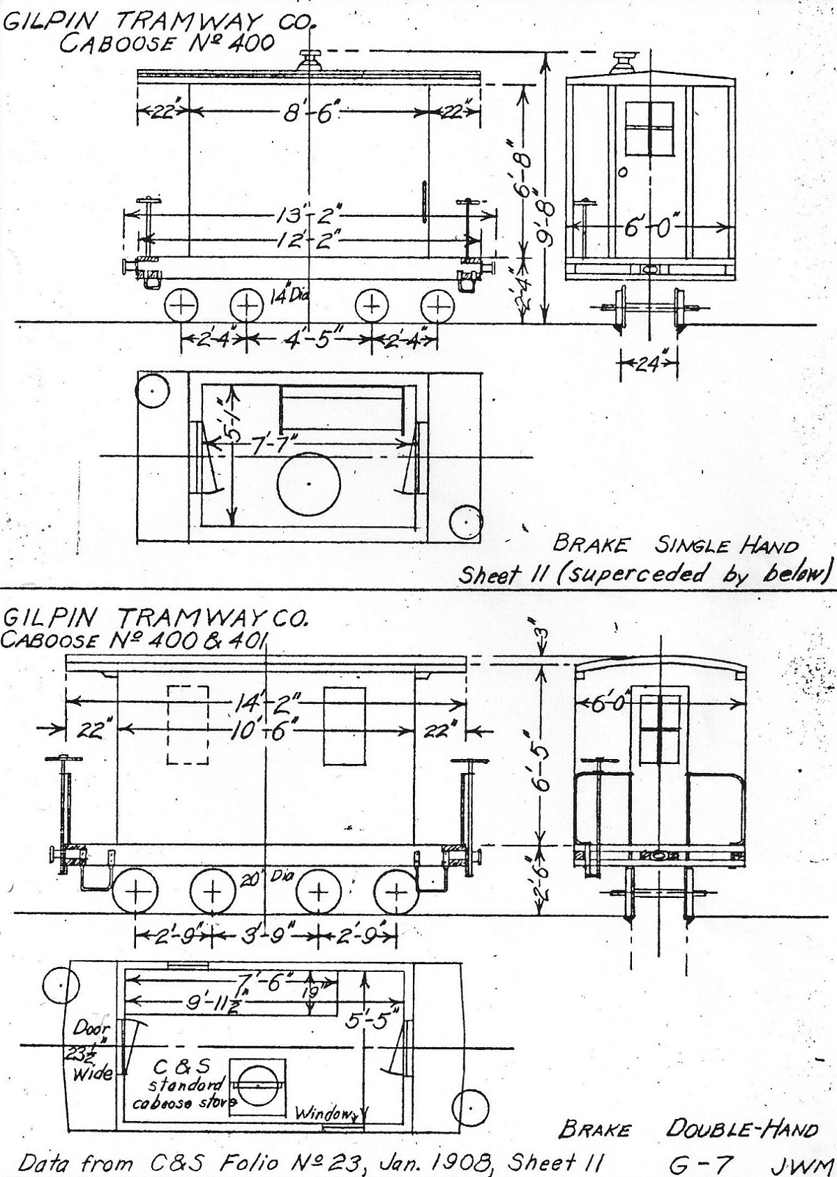
|
Re: Short wheel base South Park / C&S cabooses.
|
Ah, yes.
The Gilpin Tram- we all know they were a high-speed operation! Or were they? Those trucks appear to be strangely similar to the ones used on their ore cars. The Weyerhauser mill in Everett, WA had 18" gauge trucks, no springs, and 13" dia. wheels for moving lumber into the kilns. They probably didn't get much over a walk for speed as there was often large chunks of bark debris around the track, often getting dragged by the wheels, causing flat spots. The SR&RL also had trucked cabooses @ 2' ga., but had a much longer wheelbase, and the trucks were equalized, being the same as used under their passenger cars. I have noted a combination of square-jointed and staggered rail on the SR&RL. Their cabooses got a few more "frequent speed miles". Caboose design changed based on whether or not the user was satisfied with their performance. Designs remaining satisfactory needed no changes. Those needing frequent rerailing were subject to further scrutiny. Cheers! Stan -------------------------------------------- On Sun, 3/3/19, Jeff Ramsey [via C&Sng Discussion Forum] <[hidden email]> wrote: Subject: Re: Short wheel base South Park / C&S cabooses. To: "snapped_bolt" <[hidden email]> Date: Sunday, March 3, 2019, 10:37 PM The Gilpin Tram seemed to like double trucked cabeese. If you reply to this email, your message will be added to the discussion below: http://c-sng-discussion-forum.41377.n7.nabble.com/the-caboose-that-never-was-tp8369p13609.html To unsubscribe from the caboose that never was, click here. NAML |
Caboose 313 at Blackhawk: stop the presses!!!
|
In reply to this post by John Greenly
Hi all,
I've had some great luck. Back in the winter I spent quite a lot of effort trying to track down a better print, or even the original negative, of the infamous photo of caboose 313 on the flood cleanup train at Blackhawk. That photo may be the only one we ever find that shows any undercarriage detail of a short-wheelbase caboose. Unfortunately I struck out. I did find out that the photo has probably been mis-attributed to Joseph Collier in at least one book, and was more likely taken by Charles Weitfle. I can tell you more about this if anyone is interested. I did track down the Philip Ronfor collection, to which the photo has been attributed in another book. That collection is located at Miami University in Ohio. An extremely helpful librarian there named Cody Sprunger made an exhaustive search for me, and came up enpty. However, after pursuing other dead ends I got another message from Cody. He had come upon another uncatalogued box of Ronfor collection photos, and in it was a 4"x5" print of the 313 at Blackhawk photo!!! He scanned it and sent it along. Here it is: 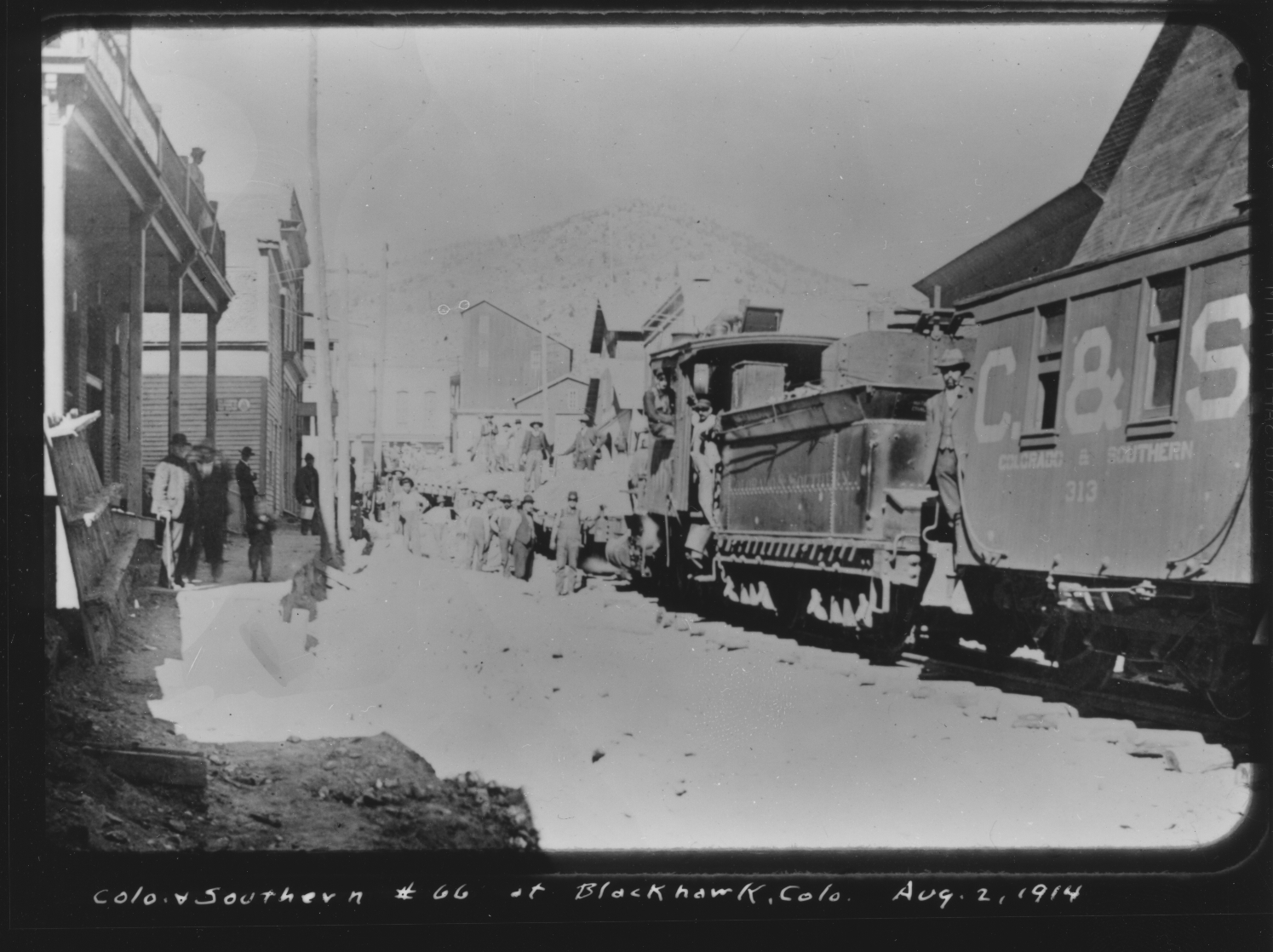 First of all, the date written at the bottom, August 2, 1914, doesn't agree with the usually stated date of 1910- this might confirm suspicions about htat date that have been suggested before. Second, as soon as I saw this print I was hopeful- it's overexposed, and so might have as much shadow detail as the original negative held. Here's a blowup of the caboose undercarriage: 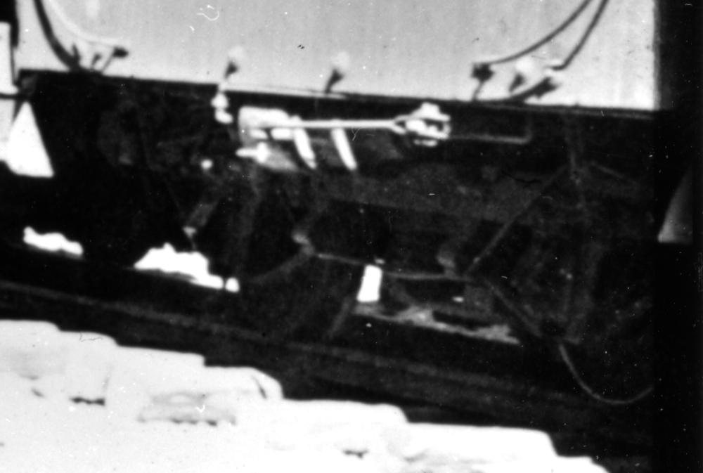 and here it is pushed to maximum possible shadow detail: 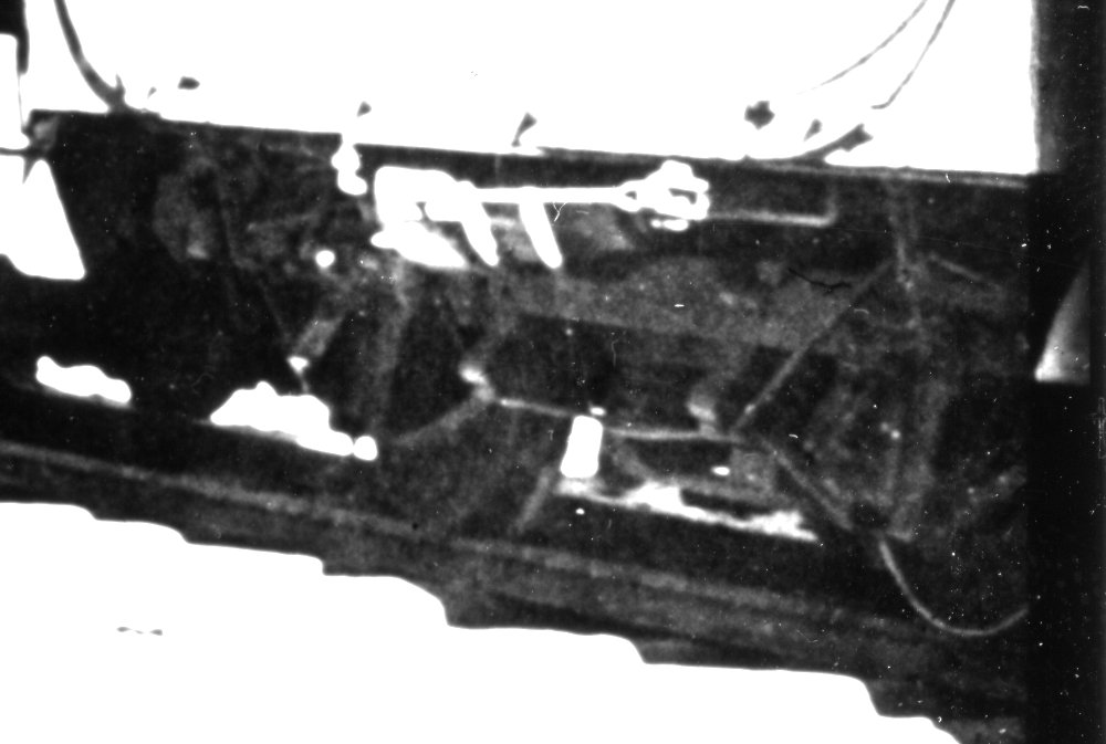 I'll just point out a couple of things, but I hope you will examine it and make suggestions. 1. there is what looks exactly like a safety chain attached to the main truck beam above the righthand journal box, connecting up to the caboose body- probably explaining the two boltheads visible below the curved handrail. 2. The rod that goes from the projecting crossbeam diagonally upward over the journal pedestal and above the main longitudinal truck beam comes back down to an attachment point on the main beam. That rod looks to be continuous from one end of the truck to the other, passing under both of the transverse projecting beams. 3. there certainly is some sort of bolster-ish assembly in the middle of the truck, but also certainly no typical leaf springs projecting out sideways. my immediate questions/thoughts: --the diagonal rod configuration looks like a stiffening reinforcement for the main truck beam. This strongly suggests that the truck is not attached to the caboose frame at its ends, but only in the middle, by the "bolster". --the use of safety chains strongly suggests that there is some degree of freedom of movement in the bolster. --if there are no visible springs in the bolster assembly, does that mean it's rigid? I still don't see any sense in there being a pivoting bolster. And, conventional springing in the bolster would allow far too much pitching of the car body with this single truck. However, the assembly that's visible in the middle of the truck could be a sort of "spring plank" without vertical springing, but with the truck hung on links allowing some motion and springing in the transverse direction, to dampen transverse shocks. This would greatly improve the ride of the car, reducing sideways lurching to which a single-truck car like this would be very susceptible. Separate transverse springing was done in some early spring-plank trucks, and these springs, either leaf or coil, would be located up out of sight behind the main beam in this view. I may make try to make a model of this to better illustrate what I'm thinking about. I'll certainly be thinking about modifying my 313 model in light of this new information. For now, here's a huge THANKS!! to Cody Sprunger, Senior Library Technician at the Miami University Libraries. If anyone wants to post or otherwise publicly disseminate the image, he asks that we please credit it to: Philip Ronfor Collection, Walter Havighurst Special Collections and University Archives, Miami University Libraries. Cheers, John
John Greenly
Lansing, NY |
Re: Caboose 313 at Blackhawk: stop the presses!!!
|
John, what a great find!
 I cannot count the number of times I've stared at the Blackhawk photo with a magnifying glass, trying to tease out details of the undercarriage. First thoughts: The presence of a visible safety chain suggests the undercarriage with pedestal journals is not rigidly attached to the frame. The undercarriage is a truck, pivoting at the center. There is no other need for a safety chain. This is consistent with the surviving Folio 27 drawings depicting a short, 6'-3-4" wheel base. Tables on the folio sheets describe a "wood bolster" and truck type being "swing beam". Early South Park / UP freight trucks of the 1880's are described as "swing beam" without visible leaf or coil springs. The reinforcing rod running below the two transverse members and up and over the pedestals, the length of the "truck", is essentially a truss rod, to keep the upper longitudinal beam of the truck (to which the pedestals are attached) from sagging in the middle over time. There is no lower side frame longitudinal beam, as on a true passenger truck. The two transverse members, double tapered on the ends, function as needle beams. To my eye there are very short "queen posts" separating the rods from the transverse "needle beam" by 1-2 inches. The diagonal, strap metal supports for the pedestals are not symmetric: The outer diagonal supports run from the bottom of the pedestal, under the journal and up to the longitudinal side frame beam. The inner diagonals run from the bottom of the journal and attach to the "needle beams" at a less acute angle. To me, there appear to be a pair of transverse transom beams at the center of the truck, with an open metal plate at the bottom, separating them and keeping them square. They are reminiscent of the large transom beams of the UP 14-ton trucks as used under the 27' freight cars. One oddity to my eye: In your second, less exposed enlargement, my eye says there is a coil spring on the left side of the space between the transoms--makes no sense though, there should be a pair of coil springs or none at all. Can't wait to see your interpretation of this new visual evidence.
Jim Courtney
Poulsbo, WA |
Re: Caboose 313 at Blackhawk: stop the presses!!!
|
This post was updated on .
Jim,
this is great- I'm very glad you're willing to come to grips with this frustrating subject yet again! All of your comments and thoughts are things that occur to me too. I agree about the truss rod and its function. I didn't call the transverse beams "needle beams" only to avoid confusion, since those are conventionally thought of as mounted to the car body rather than being part of a truck. I wonder if this truss rod was original or added after the truck was in service. It looks sort of like an afterthought to me. I'm in the middle of a very busy week so can't spend a lot of time, but for the moment I'd like to call your attention to one detail. The safety chain appears to be quite taut, there is hardly any slack in it. It doesn't have the typical slack loop that allows for truck pivoting motion. What does this imply? It would allow a small amount of sideways motion, so the swing-beam truck could function with a typical inch or so of free range to absorb sideways shocks, but it appears that it would not allow the truck to pivot significantly. I'm beginning to suspect that the main function of the chain could be to limit fore-and-aft pitching movement of the carbody. By the way, I agree with you: that does look like a vertical coil spring next to the left needle beam. And there could be another, corresponding one hidden behind the right needle beam from this angle of view. I wanted to see if someone else would say that before I suggested it. So, now think of what happens if the spring plank is sprung vertically. Those springs, if they are really there, are no more than 2 ft apart fore-and-aft, given their positions between the "needle beams". This would probably allow a sickening amount of pitching: imagine a car 13 ft long supported on springs underneath it only 2 ft apart! But, the chains, having very little slack, would go taut and limit that pitching movement, while still allowing upward deflection to absorb vertical shocks. So this would indeed be a swing-beam truck, with the bolster and swing plank assembly fulfilling their normal shock-absorbing functions. Finally, did the bolster also pivot? If so, I would be amazed if there is any evidence of these cabooses being pushed rather than pulled. Here's a challenge for all of our photo memories: is there photographic evidence of a helper engine coupled on behind a South Park or early C&S caboose, or were they always cut in ahead of the caboose? I would argue that if a helper was ever seen behind the caboose, then it couldn't possibly have had a pivoting truck. The taut safety chains would limit the pivoting/skewing range of the truck, but from that near-vertical lead angle they would be heavily stressed in the process, and I can imagine them being ripped off their attachment points. If that function was needed, a more horizontal chain attachment would be far better. However, even without the pivot, pushing on such a short-wheelbase car would invite skewing and derailment, and I would suspect that it would have been forbidden anyway. What do you think? thanks!! John
John Greenly
Lansing, NY |
Re: Caboose 313 at Blackhawk: stop the presses!!!
|
A couple of thoughts after looking at the last three posts--I need to print this photo off and dissect it with a pencil in hand!
One thing about swing beam trucks of the late 1870s, early 1880s--some, notably those made by Carter Brothers in CA, used neither leaf nor coil springs but instead rubber springs, generally housed in a cylindrical metal housing. Jokingly called "squirm motion trucks" by modern day researchers and restorers. The UP carbuilders would've known of this technology. I wonder about that chain. My understanding has been that chains were used to keep trucks nearby when equipment derailed. I really still have a problem with this undercarriage being a bolstered truck or not physically connected to the body. Truly seems a design that would not have survived after 30 years of rough operation on bad track. I wonder, given these cars likely derailed frequently, if this chain was a guarantee to assure that if badly derailed, all the parts remained close and easily reattached after a roll over, if they started to break free. A weird long shot theory but nothing in this photo seems normal. Alternately, what if that chain is related to the braking in some mad Rube Goldberg way, given the absolute lack of space, and is not related to a safety purpose for the undercarriage? I saw the coil spring on first look and would agree there's a second one hidden--they certainly appear to be used on a pivot arm. Again, I am remaining cautious on the idea of a truck floating under that body; a passenger truck on a bolster must deal with different physics than a 4-wheel car.
Dave Eggleston
Seattle, WA |
Re: Caboose 313 at Blackhawk: stop the presses!!!
|
In reply to this post by John Greenly
However, even without the pivot, pushing on such a short-wheelbase car would invite skewing and derailment, and I would suspect that it would have been forbidden anyway.
I've never seen a photo of a C&S train with a helper locomotive pushing behind the caboose. The Braddocks caboose photo seems to suggest how important it was to spare the small bobbers from compression: 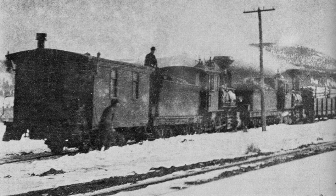 About 1901. In Digerness, The Mineral Belt, Volume 2 Other photos show helpers cut into the middle of the train, especially the four engine freights of the last years, from Denver to Leadville. A cursory look through my books and scanned photos show that even 2 engine trains, if not double headed, had the second engine cut into the middle of the train. I recall, but haven't located, a photo of the Como to Gunnison mixed train, with 3 engines--double headed on front, rear helper pushing the combine. This is the only photo that I can recall of a rear helper on a late 1930's C&S freight: 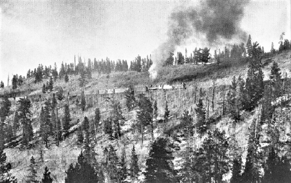 Denver Water Board photo, January, 1929. In Digerness, The Mineral Belt, Volume 2
Jim Courtney
Poulsbo, WA |
Re: Caboose 313 at Blackhawk: stop the presses!!!
|
This thread has been on hiatus but something has been bothering me about the Beaver Brook photo http://c-sng-discussion-forum.41377.n7.nabble.com/file/n6376/BB2.jpg that may tie to the overall question of the original cars' wheelbase length.
I put the Beaver Brook photo next to the best copy I could find of the CC waycar on the Loop bridge https://digital.denverlibrary.org/digital/collection/p15330coll21/id/9854/rec/1 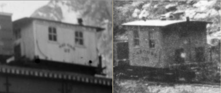 These cars are near twins except for some hardware, lettering, possible differences in corner plates (it is really hard to confirm there are corner plates in the Beaver Brook photo) and the body’s corners (are they curved or square? I just can’t tell). I see “Colorado Central R.R.” fully spelled out on the fascia and the number as 27 on the Georgetown Loop car, but your results may vary—regardless, it is a CCRR car in its earliest (ca. 1884-85) form, built Oct/Nov 1883, just after DSPP 78 and CCRR 26 and just before DSPP 79. The Beaver Brook photo, I’d guess, is ca 1886-90. I fully agree with Jim in this thread http://c-sng-discussion-forum.41377.n7.nabble.com/Caboose-numbers-quickly-diverged-to-Tiffany-Reefers-td6376.html#a6404 about the fuzzy 4-digit number but I can't decipher who owns this car. The fascia lettering is near indecipherable but to me feels less congested than that on CCRR 27. Jim, you speculated the lettering possibly being for the CCRR or UPRR, and likely not DLG or UPDG...but what about the DSPP? Other waycars were lettered as such into the late 1880s. Here's the snag for me: If the Beaver Brook car is CCRR 172x, why would two cars built at the same time for the same railroad in the same shops (Omaha?) not be lettered the same? You could argue maybe they were and that “Waycar” was painted out when the car was renumbered. But the South Park and CCRR were remote, poorly performing branches that the UP was more concerned with squeezing money out of than lavishing funds on. Repainting of the full waycar seems hard to accept given the photographic record. Another thought provoker is a tiny item in the 1884/85 Colorado Railroad Commissioner’s Report (the only year I’ve found online) for the CCRR: “May 26, 1885.—Freight. Elk Creek; brake out of order; lost control of caboose and it ran away downgrade and was derailed; damage $100.” Note that the word “caboose” is used. I’m leaning to this being a clerical decision, not a statement of what is lettered on the side of the actual car. This accident sparked me thinking about loaner cars. Plenty of DSPP equipment rode on CC rails, including the physically isolated GSL&P, so why not a caboose/waycar if a situation arose? What if the Beaver Brook car is a loaner lettered DSPP 15xx, not CC 172x? What if we incorrectly interpreted the Beaver Brook car as a Colorado Central caboose/waycar because of the photo’s location? With no specific ownership facts and a fairly consistent and clean paint job, and with rampant loaning of cars across the financially strapped UP lines, and the timing of the photo, I’m seriously considering the Beaver Brook car a renumbered South Park waycar (possibly of the final 1884 batch) on loan. Unless there's a clearer copy of the photo that shoots all this out of the sky. Now to the punch line. The Beaver Brook car has been theorized in this discussion to have a long (9’), not short (6’3”-4”), wheelbase. If true, and if this is a DSPP car, then there’s the possibility some South Park cars had been rebuilt with a long wheelbase at least by the late 1880s or even as built, earlier than what seems to be the growing thinking on this thread. This could include cars 79-82. All this is based more on what can't be seen than what can be. I still wanted to throw it out there and find out if I've missed something already discussed (digesting the lengthy and informative threads on these cars is not simple!).
Dave Eggleston
Seattle, WA |
Re: More C&S caboose under frame stuff--other narrow gauge bobbers.
|
In reply to this post by Jim Courtney
I recall reading somewhere in the last 4 decades that the D&RG short caboose was based on a caboose design used on the standard gauge Pennsylvania railroad. Not sure if Professor Sloan brings this up in his book or gazette articles...
Best, Todd |
«
Return to C&Sng Discussion Forum
|
1 view|%1 views
| Free forum by Nabble | Edit this page |

