arc headlights and dynamos

12

12

|
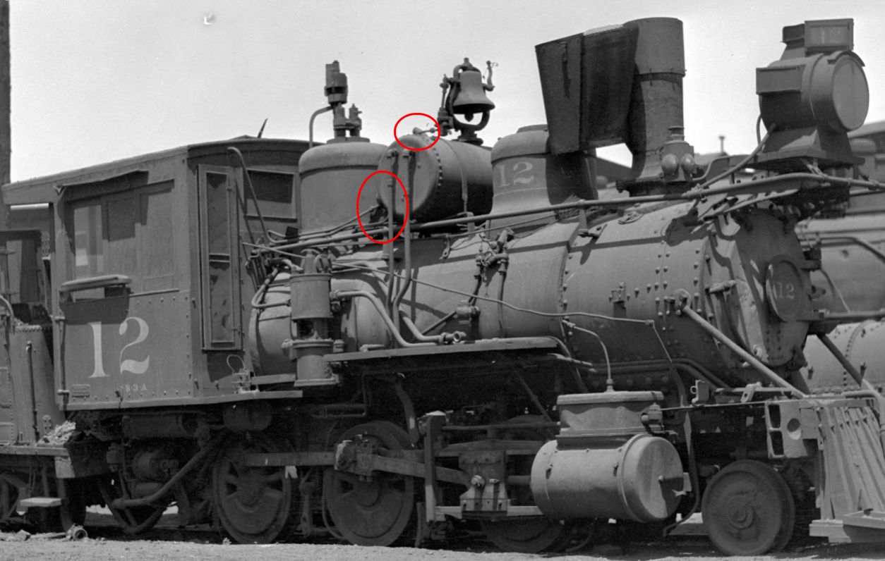
John, The outlines of the generator on #12 in the picture is somewhat shadowy, but when I looked at the air tank mounting frame extending back to the dome I was convinced. All the other bits like the cables running back across the dome to the cab just add to the evidence. Even with the little bit of detail showing for the generator itself it all fits. I agree that the tip of the stack on the fireman's side fits well. It is funny that I had already puzzled about why the #12's tank seemed farther forward than the #11 or #13. As I had just attached my #12's tank in what I think is the right place I went in and played with a generator casting in place and it fits! The tank is right at half way between the two domes. With the probable error in my guesses at angles and distances, in real life it might have been half a foot farther forward. The B3B's tanks are far forward right up by the sand dome. This leaves a lot of room for the generator. See Coleman page 79 for example with the #22. My best guess so far is that when the 1915 mandate came down, the tanks on the B3As were all 2/3s back toward the steam dome with kerosene headlights. The shop tried a headlight bracket generator on the #13 and moved the tank and put the boiler mounted generator on the #12. We don't know about the #11 as the only picture I have is earlier with no electric yet. In any case the #11 went into the river in 1916 and was scrapped soon thereafter so we may never know about her. With these experiments it was probably found that the rearward-mounted generator was better than the headlight bracket style and so the B3Bs were done in this style. The B3Bs already had the tanks far forward as shown for example Coleman page 68 and the extra space for maintenance was probably shown by the tight fit on the #12. My engineering text notes that it is preferable to mount the generator close to the steam dome or the turret in the cab to minimize the length of hot steam pipe with its consequent leaks thus we don't see many of the headlight bracket mounts continuing into the 1920s. So causing me grief? Nah! If I can get it finished, I might just have the first reasonably accurate model of the #12. Your question and this discussion couldn't have come at a better time! Thanks Skip Egdorf Los Alamos, NM
Skip Egdorf
|
Re: arc headlights and dynamos - A bit more research
|
|
In reply to this post by skip
DPL has a better version of the photo of #12 in 1921, and the generator and its exhaust pipe are clearly visible.
 You can find here on DPL's web site I remember basing the generator on the On3 version of #12 that I built from a Balboa mogul over 30 years ago on a photos, but I'm not sure exactly which photos I had access to. I think Mike Trent had this photo in his collection. I couldn't find a commercial casting that matched the photos so I had to build my own, and this photo doesn't show enough of it. I may have used photos of #13 for the details of the generator (other than location). It's been a long time, so my memory is fading. I tried to find a photo of the model, but the only one I can find is one that Rob Smith sent of it on his layout in New Mexico, but that photo is head on and doesn't show the generator. |
Re: arc headlights and dynamos - A bit more research
|
|
This post was updated on .
Hi Todd,
thanks for finding the DPL scan of this photo!! I wish you did have a good side-on photo of your On3 #12. Would you post the head-on view? It'd be fun to see. Skip, since we're being picky, here's a bigger enlargement from the DPL scan: 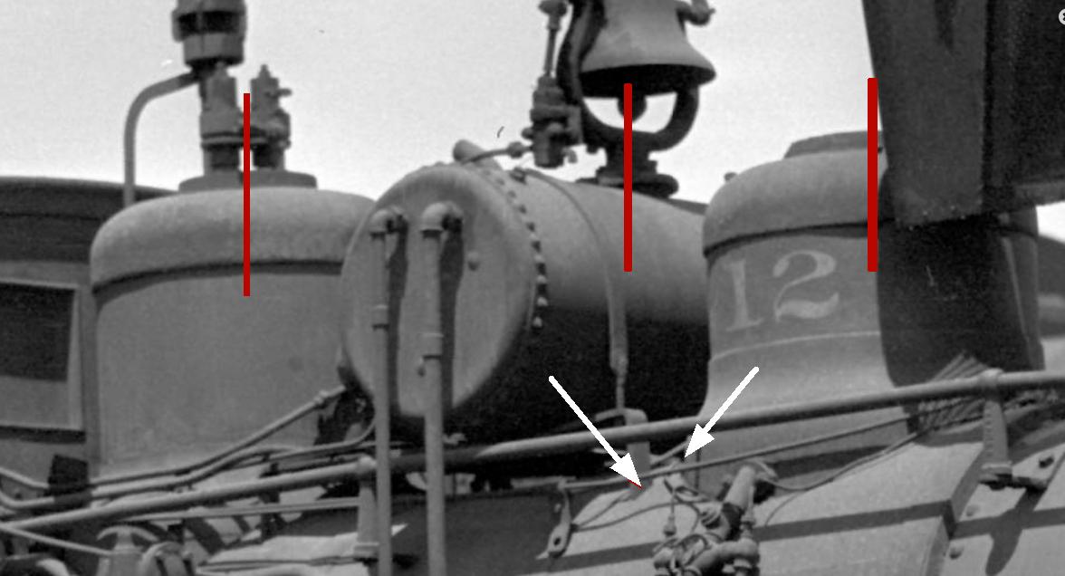 The red lines show the positions of the dome centers and the tank center. It is clear that the tank is well forward of center between the domes. Measuring these distances and taking into account the perspective (the distance is foreshortened as you move further back away from the camera) you find that the distances are in proportion about 5:9, so 5 units of distance from sand dome to tank, and 9 from tank to steam dome. That agrees well with the same measurements on the photo of #21 on p. 71 Coleman (also in DPL). Also note the position of the forward foot of the tank/generator mounting bracket bar, as indicated by the white arrows. It's very close to the sand dome base. Again, the same as on #21. I didn't mark it, but the rear foot is likewise very close to the steam dome, again like #21. I agree with your assessment that the rearward position of the turbine generator was best, the short steam line would minimize condensation problems. Probably #12 had its generator installed after experience had proved this. Cheers, John
John Greenly
Lansing, NY |
Re: arc headlights and dynamos - A bit more research
|
|
It occurred to me that I didn't check my old B&W photos. I tossed all my prints, and I didn't include the B&W negatives when I sent all my slides and negatives out for scanning many years ago (I think it was around 17 to 14 cents per frame for color, and 75 cents for B&W). I found these photos taken on August 8, 1993 on Don Peterson's old DSP&P layout in Louisville, dug out the film scanner, and digitized them. Model Railroading did a spread on this layout around the same time, and I think it had a photo or two of my #12. I thought I kept that issue when I moved, but I did get rid of most of my old magazines, and I can't find it now. BTW, I don't think you can get very accurate measurements from an oblique view like that. The apparent distance along the locomotive's axis will decrease with distance from the camera, and the amount of error from that will be a function of the distance from the camera. If the tank was perfectly centered between the domes, the distance on the photo would be less from the tank to the steam dome than to the sand dome. Since the opposite is true, it's undoubtedly shifted forward, but all you can do from this photo is estimate how far. 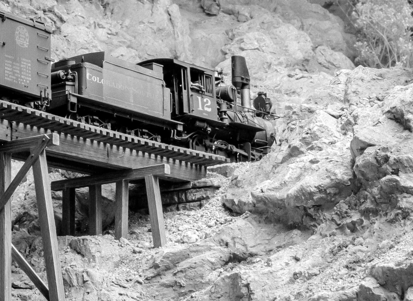 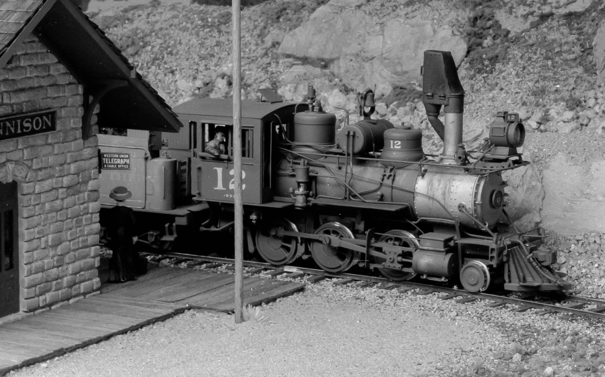 |
Re: arc headlights and dynamos - A bit more research
|
|
This post was updated on .
Todd,
thank you for finding these photos! Your #12 was a beautiful model. Makes me wish I was working in 1/4" scale instead of HO. I love the "intermediate" tender. As to deriving dimensions from an oblique photo view, I agree with what you said exactly, if you have no other information it's impossible to find the actual dimensions. But we do have other information, various dimensions on the engine that are known. I won't go into a big lecture here, but if you know the dimensional relationship among four coplanar but non-collinear points in an obliquely oriented plane in a photo then you can exactly determine the position of the camera with respect to the object, and then derive the positions of all other points in that plane. And with additional information in orthogonal planes, you can in some cases unfold all positions in three dimensions. We have such information, for instance the size and spacing of the drivers on the locomotive, and also a number of other dimensions, so we have redundant checks on accuracy. It's laborious, not always possible to carry through, and its accuracy depends on the specific configuration and how much dimensional information you have. I didn't do a complete job on the tank position on #12. I said the tank position was "about" 5:9 between the domes. That's not just the direct measurement of those lines I drew, it includes a first-order correction for the oblique perspective, using the drivers for reference. I know from other experience that this correction should give the ratio within better than 5% of the actual value. With more work it would be possible to get those dimensions within an inch. With a photograph of this quality, and knowing enough reference dimensions, it's even possible to measure and correct for lens aberrations in the camera. If you have multiple photos of the same object from different angles, that's even better. anyway, Cheers, John
John Greenly
Lansing, NY |
Re: arc headlights and dynamos - A bit more research
|
|
In reply to this post by Todd Hackett
Fantastic modelling, Todd!
|
|
|
In reply to this post by Todd Hackett
Todd,
Thanks for your photos of your #12 and the bit of history on placing the generator. I know that my HOn3 effort won't match yours, but I hope to get kind of close. I do think that your model has exactly the right look to it. I tried to do enough trig to get a good approximation to the tank position. I think that a distance and angle correction moves it is a bit back from the B3B's 5/9 ratio that John measured. I now think I know how I over corrected the angles resulting in my estimate of the tank about half-way back. John is correct is describing the great detail that can be provided analyzing the angles and distances from a flat photo and I did not do the full suite. At the same time I am not sure that the B3Bs provide a strict prototype for the #12's tank position. Their tanks were already far forward between the domes before electrification and the #12's tank would have been moved forward to do the generator installation. So close, but probably not identical. This forum has once again really shown its value. The discussion and throwing ideas back and forth has taken me from a question about how the headlight was powered and why the tank seemed further forward in the pictures to a much better understanding of how the #12 was put together. Thanks everyone. I'm forever in your debt. Skip Egdorf Los Alamos, NM
Skip Egdorf
|
Re: arc headlights and dynamos - A bit more research
|
|
This post was updated on .
Hi Skip,
thank you for your contributions to the discussion! I look forward to seeing your model. I apologize if I was not clear in my post, but the position I gave for the tank was indeed measured from the #12 photo, not the B3B's. It is true though that the photo of #21 gave me very nearly the same result. One very nice thing you can do before fastening your tank permanently is to take a photo of your model from the same viewpoint as the prototype photo and compare directly. You can do this with no mathematics at all. Use your camera to photograph the prototype photo- lay it flat and photograph straight on. Then just by trial and error you can take pictures of the model, moving the camera until you get the image to exactly correspond to the prototype image at four widely separated points, say for instance the top and bottom corners of the cab, the top of the stack and the pilot beam end. That'll get you the same perspective on the model, and then you can compare the tank position directly. When I do one of these measurements I always try to check my work this way. I stick pieces of tape onto the screen and make pencil marks for the reference points. It's important to match them exactly. I use an iPad camera for this because the screen is big enough to use directly without having to download onto a computer to look at. iPad or cell phone cameras are generally excellent for model photos because their tiny optics give great depth of field in closeup use. It's interesting- the lens aperture and focal length of a phone camera is in fact a miniature scale model of a full-size camera. If you had one with aperture and focal length scaled down by 1:87, it would act optically on HO scale scenes exactly like a big camera would on the prototype. If that were true it would mean that the depth of field in scale feet would be the same as the depth of field in real feet for the full-size camera at the same numerical aperture (f-number). Just looking at the size of the lens, I think phone cameras might be roughly in the neighborhood of O scale. Cheers, John
John Greenly
Lansing, NY |
|
|
In reply to this post by skip
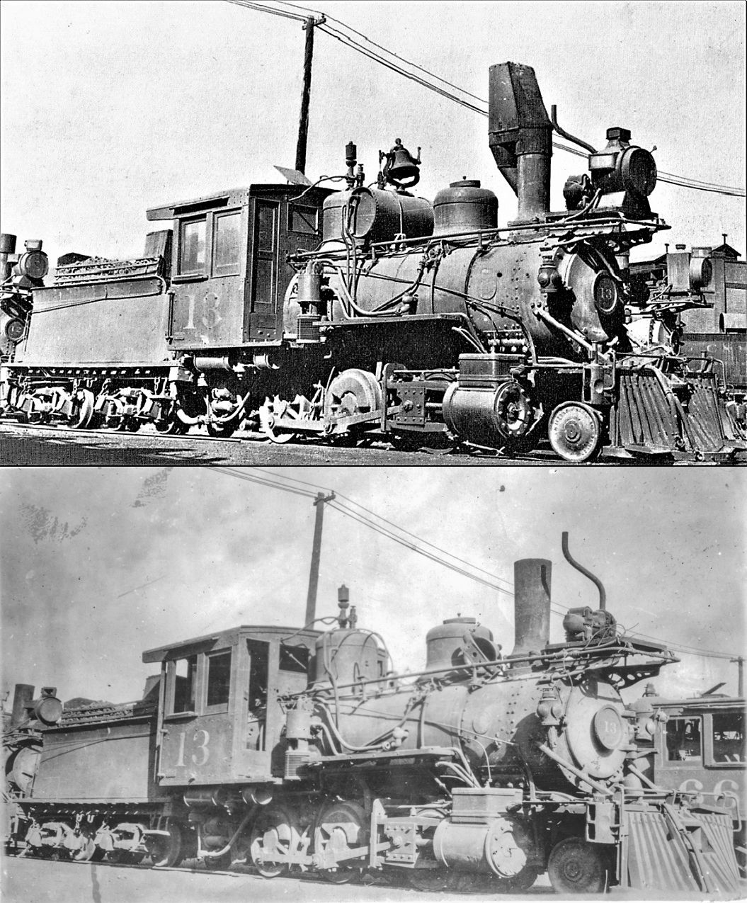
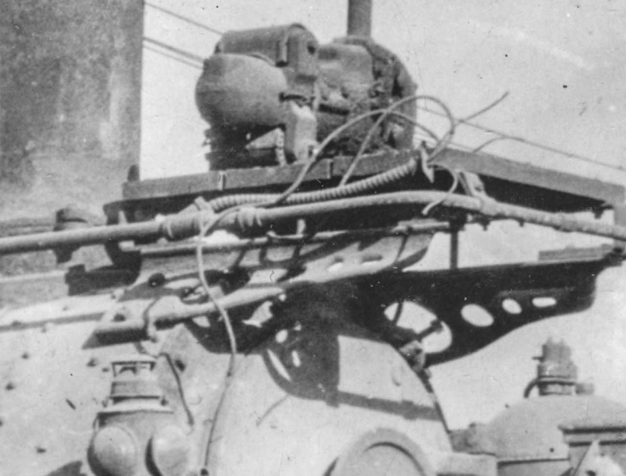
How often do we get two photos from the same angle but at different times? Here's Skip's photo and another taken from almost the exact same spot after #12's number boards have been broken and #13's headlight has been removed exposing more detail on the dynamo and it's air tank removed, bell sitting on the handrail, doors open or missing, etc. It also shows the wires coming out of the flexible conduit where the headlight had been. It's interesting that the classification lights are still there.
|
|
|
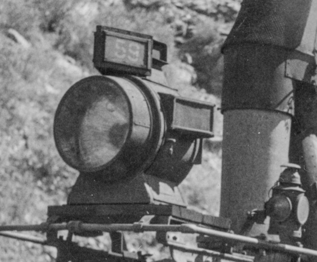
Here's another nice view of one of these headlights, this time from C&S 59 at Black Hawk, taken September 28, 1923 (hand-written in the margin of the stereo view). It's hard to tell, but I think I see a conduit coming from the handrail on the engineer's side to the headlight.
|
|
|
Todd,
I think you're right, there is a conduit to the headlight there just behind the front leg of the bracket that supports the light platform. And in this same photo uncropped you can see the exhaust stack of the dynamo poking up behind the air tanks. Thanks for finding this one, as well as the others of #13 earlier! John
John Greenly
Lansing, NY |
|
|
Here's the whole image (nice 3D effect for anyone with a suitable viewer):
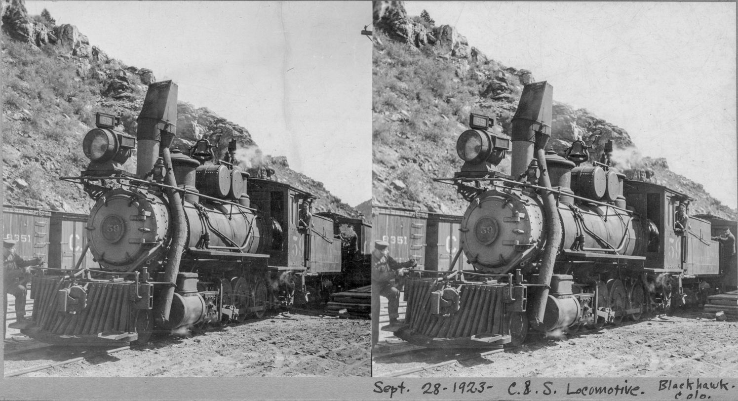 The visible portions of the conduit going to the headlight: 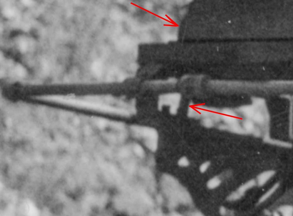 And the exhaust from the dynamo: 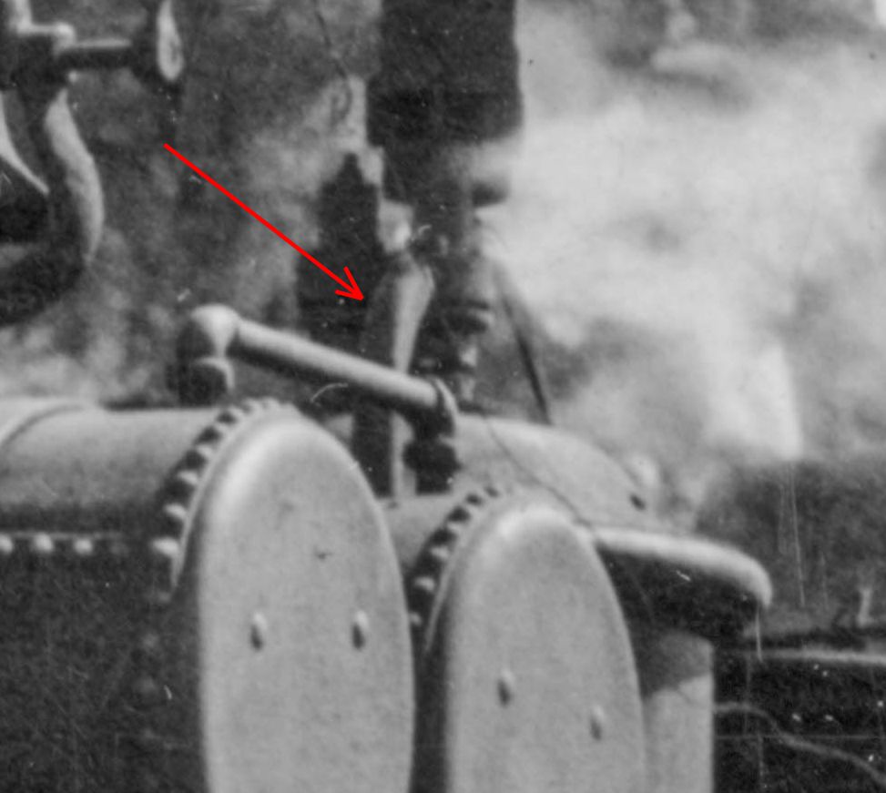
|
«
Return to C&Sng Discussion Forum
|
1 view|%1 views
| Free forum by Nabble | Edit this page |