Type C/UP trucks

123456

123456

|
Got my Sn3 type C trucks yesterday, very nice! After just a quick look, I see we have to rearrange the brake beams. Any guidance on that? Not sure what I'll use them under yet.
Thanks, Mike |
|
|
Mine arrive tomorrow!
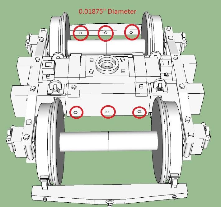
I placed three 0.0188" diameter holes in each brake beam and and through the bolster. The brake beam holes are 0.034" above the holes in the bolster, so you'll need to bend the wires if using a single piece of wire from beam to bolster to beam. I'd do that with a jig. The top of the axle is 0.09" above the brake beam holes, if you want to run the wire over the axles. The brake beams should be about 1.2" apart (and the brake beam holes are 0.03" deep) An alternative would be to use a pair of 0.018" wires which are 1.2~1.3" long, running from beam to beam, connected via jig drill brackets to other wires passing through the bolster...which could allow for the brake beams to be readily removed. Note: these holes also allow the use of wipers for power pickup or to secure a contact or such (per Jim's interest in power pickup). Michael |
|
|
My Sn3 test print will arrive tomorrow as well. Perhaps Michael can illustrate his concept of making a jig for bending the brake beam support wires. (I love jigs!!
 ) )
Jim Courtney
Poulsbo, WA |
|
|
 Here are the holes for mounting the brake beams Mine arrived yesterday. I left them outside for a couple hours to be assured that the acrylic has fully cured, but I haven't cleaned them yet. All of the prints look really nice. The On3 version is free rolling. Both materials printed, but the detail plastic definitely looks better. The journal lettering is legible. It was a bit of a tighter fit to slide the axle into place. The HOn3 version isn't free rolling. I'm not sure if that is due to the wax. My 2-1 seating for Combine #20 shall get a new thread...I'm excited about those. Michael |
|
|
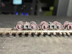
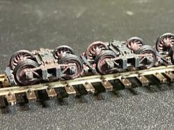
The Sn3 test print of the Type C trucks arrived. They look fabulous and roll very well:
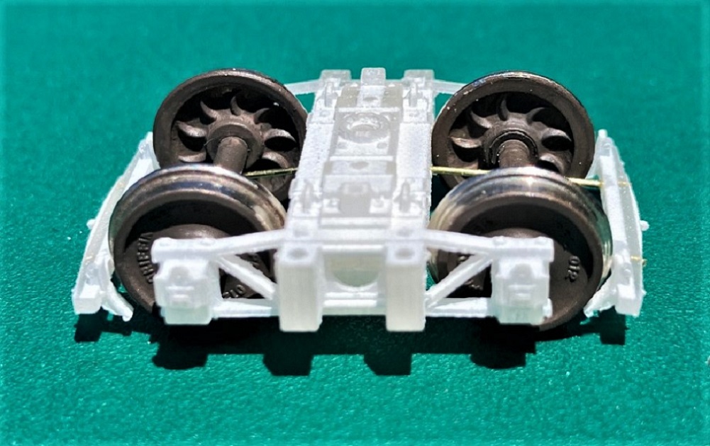 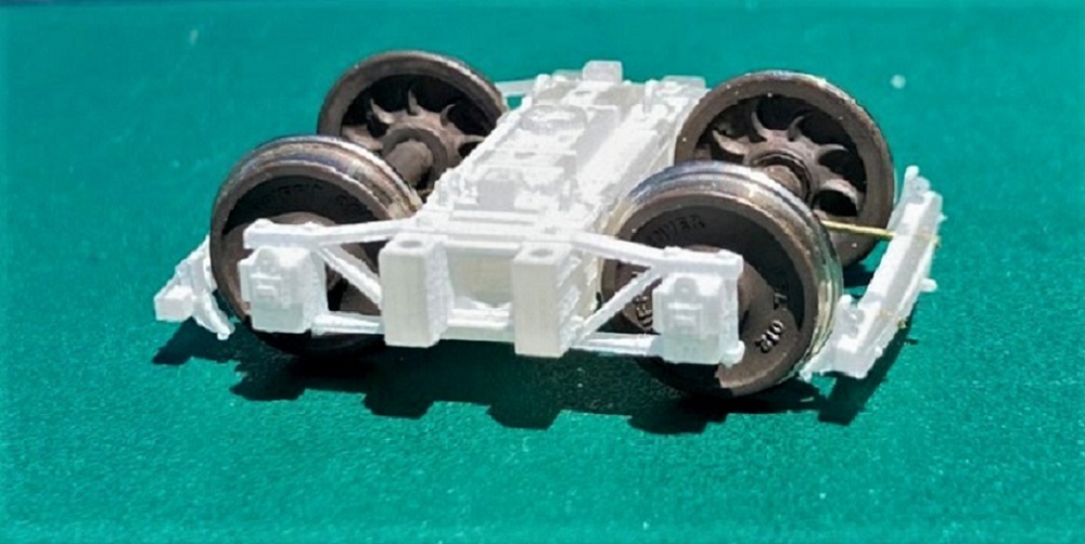 My photographs don't do them justice. Hopefully I can prime and paint a pair this weekend, so the detail is more apparent. On arrival, I was astounded by the rendering of detail on the side frame, bolsters and recessed springs. I wanted to immediately separate them into the component parts and assemble them, but followed my usual Shapeways ceremony: Placed in direct sunlight for 2 hours to ensure the acrylic had completely UV cured. Soaked in Bestine for 30 minutes to remove residual wax. Wash in my ultrasonic cleaner with warm water and Dawn. finally a rinse in distilled water and air dried. I clipped the larger supporting sprues apart with my PBL sprue nipper, used the small/fine nipper to separate the brake beams from the side frames. All sprues then trimmed flush with sprue nippers filed smooth as needed. The print is translucent on arrival, becomes chalky white after cleaning. On to inserting wheel sets--I'm using my stash of PBL's last iteration of 26" wheelsets, with code 88 treads and flanges, cooling ribs on wheel backs. Older wheel sets with standard treads may not fit. CAUTION: When spreading the side frames to insert the wheelset axles, go slowly and gently. This isn't Delrin. The acrylic print is brittle and if you rush it you can snap the side frame off the bolster, impossible to repair. Ask me how I know . . . The first wheel sets installed produced an extremely free rolling truck, almost as good as PBL's "RTO" trucks from China. The second set of wheel sets in the second frame were much more sluggish, a puzzle. It took about 15 minutes to figure out that the problem wasn't Michaels print, but the PBL wheelsets. All is not groovy . . . Michael, clever man that he is, has tried to maintain the truck dimensions as close to scale as possible and still accommodate our slightly over sized wheels and flanges. The transoms have a vertical groove printed in them to clear the flanges on a strict 4' wheelbase (orange arrows): 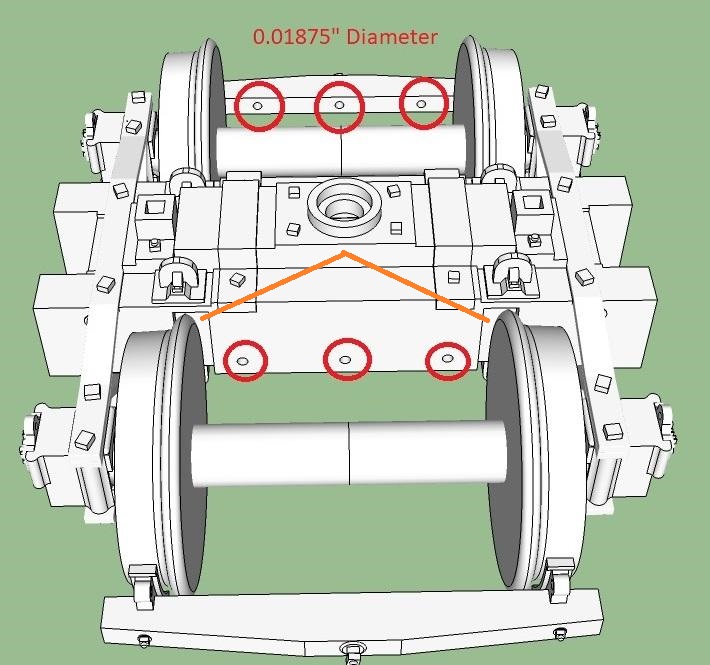 With my micrometer, I found that not all PBL wheelsets are created equal. On 4 of 10 wheelsets checked, the wheels, while in perfect gauge, were mounted on the axles asymmetrically, with one wheel up to 0.010" closer to the axle tip than normal, the other up to 0.010" further away from the axle tip than normal. This causes either the front of the flange or the rear of the flange to rub against the edges of the printed grooves. So much for Chinese manufacturing quality control. We're goin' to need wider grooves in Sn3, Michael. Michael's design for mounting the brake beams is doable but tedious. The photo illustrate my process better than words: 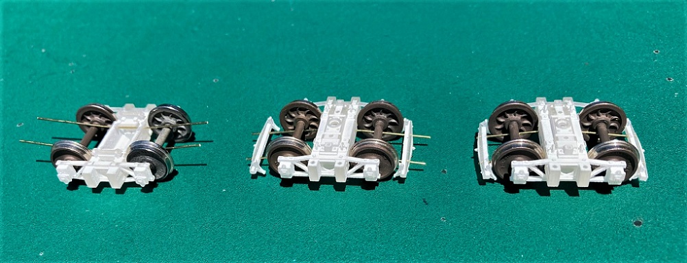 I cut Detail Associates 0.019" wire into lengths 1.75 inches long and dressed the ends. I drilled out the outside holes in the transoms and brake beams with No. 76 drill (0.020"). I drilled all the way through the brake beams. I threaded the wire thru both transoms and centered it, secured the wire with ACC so it wouldn't turn in the holes. I then used my long nose pliers to bend the four pieces of wire downwards, gestimating when the wire would clear the axles from below. The wheel sets have to be re-installed to check axle clearance and this is problematic, as the wire is now very close to the back of the wheel, requiring the side frame to be spread further. This is how I broke one of mine. When the four wires had been further tweaked by bending and clear of the axles, I slipped the brake beams on the two wires, positioned them so the inside edge of the brake shoes were about one flange distance from the tread and secured the brake beam to the wires with ACC. I then clipped off the wire protruding from the brake beams with my small flush cutters and filed them smooth. To make the brake beam lie horizontal required further tweaking/bending. If we are going to use wire to mount the brake beams, I would prefer this method: 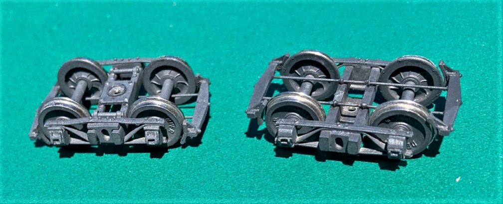 This is my standard Type-B 20-ton Peninsular truck in Sn3. Eric Bracher's Rio Grande Models produced them as kits years ago. As I prefer the PBL wheelsets, Eric produced enough side frames and transom/bolsters for me for abut 15 pair. I used The Leadville Shops brass brake beams. The casting has indents, like Michael's little holes, and I drilled them out, all the way thru, like on the printed brake beams above. Same 0.019" wire was used, one brake beam casting soldered to the two wires, making sure everything was square. I threaded four Detail Associates wire eyelets on the wires. The bottom of the white metal truck transoms were marked and drilled about 1/4" deep with a number 80 drill. The eyelets were inserted into the transoms bottom and press fit. The wires were then slid thru the eyelets until the attached brake beam was positioned near the wheels, then everything clamped in place. The other brake beam was then slid onto the wires, positioned near the wheels on the other wheelset and soldered (or ACC'd) into place. With everything centered the four eyelets were ACC'd into the transoms and to the wires. Once one set of brake beams is assembled, the back-to-back distance of the brake beams can be measured, and all future brake beam assemblies can be assembled separate from the trucks, then pined to the bottom of the transoms, centered, then glued into place. I like this method because all the wire stays straight, is mounted flush with the bottom of the transom, is well below the axles without bending, and the brake beams end up level in both dimensions, in the same plane as the support wires. Whew, I didn't intend to be this wordy. I'll take a break, do some measuring, then come back and add a list of adjustments to Michal's print in Sn3, that I would suggest . . .
Jim Courtney
Poulsbo, WA |
|
|
Funny thing, I’ve noticed the same issue with On3 wheelsets! I’m especially careful to check for burrs on the end of axles…a few NWSL axles had these a few years back…
I managed to snap off one of the journal boxes on an HOn3 version of this…I’m thinking about beefing up the arch bars on that one…it worked fine so long as I was careful, but I wasn’t carefully on one of my tests last night… I think that version could also benefit from slightly more space for the axle length as they seemed be a little tight. I would recommend a journal/truck turner tool to make sure that the axle hole is clear of wax or to deepen it slightly if desired. For On3, I like shoulder axles, but I do plan on using needle points for trucks with 26” wheels (SJCC needle point axles). I’ll widen the grooves. Would you prefer that I have holes printed in the bottom of the transoms so that you can just pin them from the bottom as you did? Feel free to post your list of edits and thank you for helping me work out the details for Sn3! |
|
|
Michael, I do love these trucks, just what the doctor ordered! I've ordered two more prints of the current iteration to experiment with.
But they need to be durable to operate, and this iteration, even in S scale, is a bit too fragile. I snapped off another side frame trying to carefully remove a wheel set, so I could prime the truck. The weak point of the side frame are the three "bars" of the archbar, especially the top and bottom, where they attach to the side of the transom. My suggestions: 1. Beef up the bars. Yours measure 0.012' thick by 0.050' wide. By comparison, Eric's RGM white metal side frames are 0.015" thick and 0.060' wide. PBL's one piece Delrin archbar truck has bars 0.018" thick at front edge and 0.060 wide, but they engage in a bit of trompe l'oeil--the top and bottom bars have a top surface that is flat, but the bottom surface falls away at an angle, creating a triangular cross section. The front of the bar is 0.018" thick but the back surface is 0.025" thick. I like the delicate look of your current arch bars, but similar dimensions probably wouldn't be noticed. Besides, the real eye candy of your trucks are the journal boxes with the beautifully detailed lids and the center plate with its circular cutout, visible springs and tie rods. 2. Do everything possible to minimized spreading the side frames. If possible, spread the inside surface of the side frames about 0.020" total, make the axle holes more shallow by 0.010". The PBL axles fit the current axle hole dimensions perfectly. As long as you don't mount a hinky wheel set, they roll very, very well. 3. If you are intent on keeping the wire mounts for the brake beams, pull each of them in toward the centerline. Your wire to wire distance is currently 0.34". The distance between the two wires that support my cast brass brake beams is 0.26". The current location of the wires limits movement of the wheel set as you are trying to insert it. When you seat one axle in a journal hole, then gently spread the opposite side frame to seat the other end of the axle, you are actually transmitting force down the length of the axle and spreading the opposite side frame a bit as well. The current wire locations trap the wheel, prevents the axle from moving backwards and requires the one side frame to be spread even further (that's when mine break). 4. I'd widen the flange grooves by about 0.020", 0.010" each way. 5. I would prefer that the bottom of the transoms be printed full width--there is plenty of room for a 2 mm screw head in between. And if you could print 4 divots on the bottom, the same distance from the centerline as the brake beam holes, that would give me a drilling mark for my wire eyelets. Unless . . . the other option would be to print a small flange on the inside surface of the transom bottoms, like on the bottom of the transom of these TLS brass trucks, with the two holes for brake beam wires located so they are flush with the transom bottom: 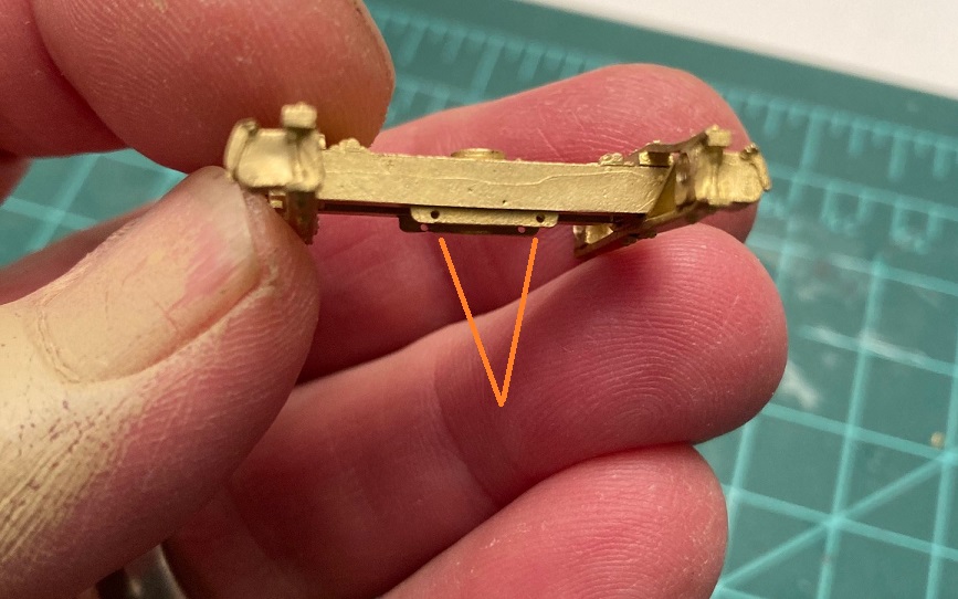 The holes in the flange take the place of the eyelets--just insert two straight pieces of wire, glue in place, then slip the brake beams in on each end. Is there any solvent or glue to be used to repair the broken acrylic parts? Is there a solvent that will melt and weld the stuff, like MEK welds styrene together? Jim
Jim Courtney
Poulsbo, WA |
|
|
One other thought on the issue of side frame breakage:
I was able to insert the PBL wheel sets in each of the 4 trucks in my test print successfully the first time. I was able to repeatedly remove and reinsert the wheel sets several times before the side frames on two of the trucks snapped. This is my first experience with printed acrylic trucks. Perhaps the acrylic material likes to stay rigid, and the repeated spreading of the side frame causes stress and fatigue in the acrylic material, leading to the breaks. Now that I know that the printed trucks and PBL wheelset have excellent rolling characteristics, I will "trust the print" with my next order. Meaning that I will clean the printed parts, install brake beam support wires and brake beams, prime and paint the trucks, paint the wheel sets separately, and then install the wheel sets one time only, trying to never remove them. We'll see . . . 
Jim Courtney
Poulsbo, WA |
|
|
You got my wheels turning...bonding acrylic with something other than CA. Looks like the two products have potential here: SCIGRIP #4 and #16. I'm going to order some, if I can't find it locally.
I ended up playing with 1:1 scale trains this weekend, so I didn't make any revisions to the model trucks. I'll get to them when I have a chance. Michael |
|
|
Interesting, Michael.
SCIGRIP #16 looks to have the shortest bond time of 5-6 minutes, perhaps best suited for model work. The other looks like a contact cement for acrylic. I ordered a pint can of the #16. Will compare notes . . .
Jim Courtney
Poulsbo, WA |
|
|
Awesome! I saw someone on youtube comparing them against CA for sheet acrylic, and he reported them to be way better. I hope we see the same! I've made all the modifications to the Sn3 truck, except the archbars which are in-progress. I might try a few different versions and post screenshots...
|
|
|
Thanks, Michael.
My second order of test prints from the first iteration just shipped. I'm going to experiment with different ways of mounting the brake beams, and minimized spreading the side frames. I noticed a crack on one of the arch bars on a couple of the trucks that broke from the first test print, before the side frame snapped off. I tried repairing it with ACC, but if this new stuff will actually weld the acrylic together, it might be a better solution. Jim
Jim Courtney
Poulsbo, WA |
|
|
Here are the revisions:
1. Arch and tie bars are now 1.25" thick in S scale (0.020"), but the tie bar and the angled portion of the top arch bar have a triangular cross section which is 1.5" thick in S Scale (0.024"), with the extra width added on the bottom. 2. The space between the journals was 0.73" with a gap that made it 0.75" in the middle, now they are 0.77" apart. 3. The wire mounts for the brake beams are closer together, now 0.25" center to center 4. Grooves widened by 0.01" each way. 5. The transoms are now full width and have the mounting holes in a flange which is in-line with the brake beams. Previously, the transoms were reduced width to minimize the material costs of the trucks. In O-scale, swing motion trucks eat up 2-3x as much material as rigid thanks to the transoms. Michael 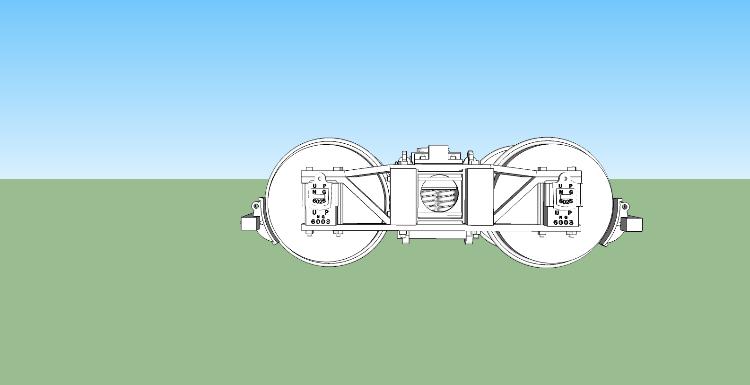 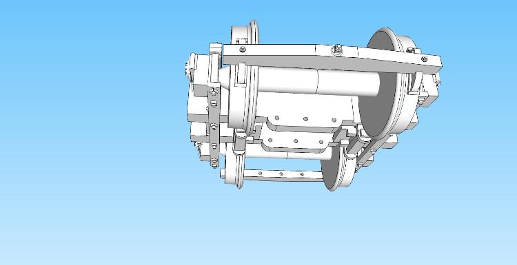
|
|
|
This looks great, Michael.
On question--what purpose does the middle hole serve?? The outer two holes for wires is sufficient to support the brake beams. At 0.25" apart, two 0.019" wires support my brass brake beams quite well. If the hole is for a wire for axle pickup for electrical power, I would move it: I will use 0.012 or 0.015" phosphor-bronze wire for pickups. I'd prefer to run a single piece of wire through both transoms, soldering electrical wire to one end of the wire, just outside the transom (before inserting the wire thru the transoms). Move the middle hole left or right a bit, out of the way of a screwdriver, mounting the truck to the bolster. Keep that hole at the previous vertical height--the wire needs to touch the axles. Make the hole smaller, 0.012 or 0.015", for the phosphor-bronze wire. I've never added wire pickups to trucks--anyone have recommendations as to minimum wire diameter?
Jim Courtney
Poulsbo, WA |
Re: Type C/UP trucks -- S scale experiments
|
|
This post was updated on .
While waiting for Michael to post the new version 2.0 of the S scale, type C truck to Shapeways, I ordered a couple of prints of the original iteration to experiment.
I intended to try attaching the brake beams using the eyelet and wire design that I've used for my type B trucks. But the original print doesn't have full width transoms on the bottom. Michael designed a carve out (likely to save plastic and lower cost). I tried various thicknesses of Evergreen styrene strip and found that 0.030 thick stock fit snuggly in the space. With 0.030 x 0.188 strip a flange would protrude from the bottom of the transom, as Michael has designed in version 2.0. So, I used my micro-razor saw to cut a bunch of rectangles of styrene 0.030 x 0.188 x 0.41 inches. I laid out and drilled two holes in the rectangles for wire, some 0.20 inches apart on center and the others 0.25 inches, for the brake beam wires. I placed the rectangles partially into the space, threaded 0.019' wire through the two styrene rectangles, then seated the rectangles, so the wire was flush with the bottom of the transom. After brake beams were drilled and installed this is what I can up with: 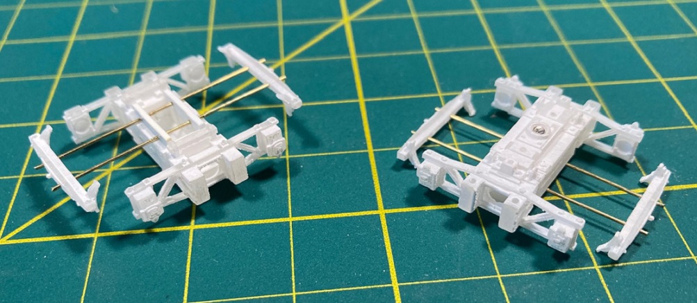 The styrene flange replaces the eyelets in my original method. A note about drilling the brake beams, as I've broken a couple in the process. I gently clamped the triangular part of the beam in my Panavise, then marked the location of the holes ether 0.20" or 0.25" apart. I found that if I started the hole with a #80 drill, then drilled through the brake beam with a #78 drill and finally enlarging the hole with a #76 drill, no breakage occurred. Seems tedious to drill the same hole 3 times, but I didn't break any of the 16 brake beams. I had hoped to glue the brake beams into position on the wires, paint the entire truck assembly, then insert the separately painted PBL wheel sets as a last step, once and once only, to minimize the chance of breaking the side frame. But this doesn't work. If the brake beams are glued into position, it is impossible to insert or remove a wheel set without breaking the side frame: The free axle end of the wheel set must be inserted into the spread side frame from the end, not the top. The fixed brake beam prevents this. BTW, there was no advantage in having the support wires only 0.20 inches apart. A distance of .025" is sufficient to manipulate the wheel set into position So, I merely mounted the brake beams on the support wires (0.45" from brake beam edge to transom side), but didn't glue them. The axle holes were masked off and the entire assembly was air brushed with Polyscale "tarnished black"; the PBL wheel sets were airbrushed with Polyscale "roof brown" in a Banta tread masker. When the paint was dry to touch but still soft, I gently removed the brake beams from the support wires. Then, slowly, carefully installed the painted wheel sets--didn't break a single side frame on the four pair of trucks!! The brake beams were then remounted on the wires, position checked so the brake shoes didn't rub wheel treads or flanges and the brake beams glued with ACC. After the protruding wires were cut off flush and paint touched up, this is how they looked: 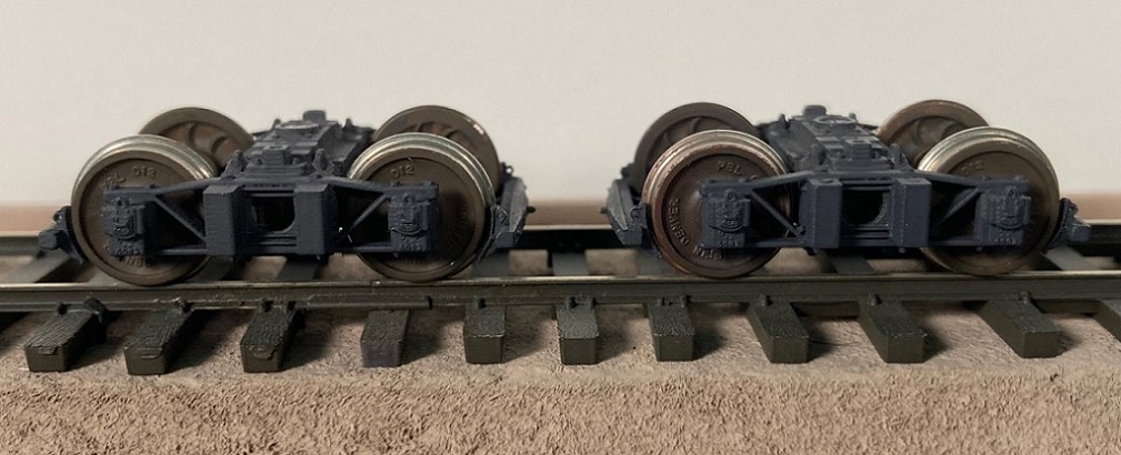 Michael's S scale trucks are gorgeous! I particularly like the way the transom tie rods are delicately rendered in front of the circular cut out. And the journal boxes are each little pieces of jewelry. Note the lift rings on the journal lids. The raised UP lettering and numbers are legible under magnification. Alas, the spring set gets visually lost in the black hole beyond the circular cut out. The assembled trucks are also very free rolling. If PBL R-T-O trucks are a 10 in terms of rolling, these are an 8. Here is how the S scale type C, 14 ton truck compares to the RGM type B, 20 ton truck: 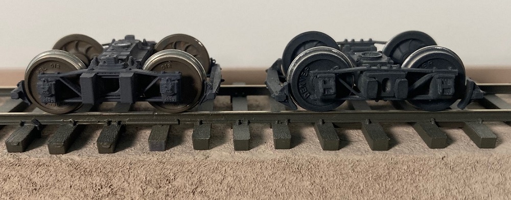 And here is how Michael's trucks look under two of the 27 foot cars that the prototype carried:  I did find an adhesive that will repair the acrylic if it breaks, the "Cool Chem" cyano-epoxy system: https://coolchem.com/products. This stuff was supposedly created to attach the outer skin of the stealth fighters, thus avoiding rivets that might produce a radar signature. On the one surviving trucks of my first print, I noted that the diagonal and bottom bars had broken where they join and meet the transom. The side frame was being held in place only by the top bar. The Cool Chem system requires the two parts to be joined be brushed with a primer liquid, then a small amount of the cyano-epoxy resin was applied with a piece of wire. With the two parts held in alignment together with my fine forceps, one puff of the activator was sprayed on. The resulting joint seems as strong as the original acrylic. This stuff will supposedly glue Delrin to Delrin, too -- folks evidently use this stuff to repair broken Delrin handrails on HO scale diesels. I want to thank Michel for all the work he's put into the type C trucks. They've inspired me to move on to other projects that used this 14 ton truck, namely the Tiffany Reefers c.1901. Both the 26' and 27' Tiffany's used these trucks. I'm looking forward to getting prints for Michael's second version of this trucks, as assembly will be much quicker. If the HOn3 and On3 prints of this truck turn out as well, folks are going to be pleased. And all you 1930's model builders need to remember that these trucks were in common use under the 27 foot outfit cars, for your MOW train. And (ahem) it sure would be nice to have those 12 ton Litchfield trucks printed in S scale . . .
Jim Courtney
Poulsbo, WA |
Re: Type C/UP trucks -- S scale experiments
|
|
We need a "jaw dropping" emoji. I have a hard time believing that the trucks I drew look that nice! Obviously, the painting and assembly made them much better!
Version 2.0 is out in On3, Sn3, and HOn3. On3 and Sn3: https://www.shapeways.com/product/DAZ7DQRRR/dsp-p-type-c-up-14t-trucks-2pr?optionId=219665953&li=shops HOn3: https://www.shapeways.com/product/QRCC48S2S/dsp-p-type-c-hon3-4pr?optionId=219952928&li=shops I have not test printed them, but there was much pain with little non-manifold errors that were tough to trace. All three versions use the more robust sideframes which are 1 1/4" thick material on the outside. Yep, the non-prototypical thickness on the transoms was 100% cost saving, but I think I overestimated the savings. The holes now pass fully through the brake beams so we shouldn't have the need to drill any more out. I could make the brake beams available as a separate bulk pack (I thought I'd done this years ago, but evidently I forgot to click the "for sale" box). I dropped the middle hole and added two new holes for wire that are at around the right level for axle wiping. I'd prefer to have them each only touch the back of the wheels so that 4 wheel pickup is achieved on each truck. I've previously done this with an HO 0-6-0 for my son. The Litchfield revision is on the agenda now. |
Re: Type C/UP trucks -- S scale experiments
|
|
I can tweak the journals.
Try spreading them just slightly to see if a little extra width would help them roll more freely. I'd also recommend trying a truck journal tuning tool, just in case there is some residual wax in the journals. |
Re: Type C/UP trucks -- S scale experiments
|
|
I could make the brake beams available as a separate bulk pack (I thought I'd done this years ago, but evidently I forgot to click the "for sale" box).
How about a brake beam set of 9 or a baker's dozen --13. Would provide an extra to replace breakage. I have a knack for breaking Shapeways prints, and I don't even own a "break wheel", like Jeff. Michael, do you have a link for a truck journal tuning tool? Will it fit between the journals of an Sn3 truck? I'm quite pleased with the rolling qualities of the trucks as is. I fear pursuit of perfection will lead me to breaking more things! Let me try the version 2.0 print before you do any more tweaking.
Jim Courtney
Poulsbo, WA |
Re: Type C/UP trucks -- S scale experiments
|
|
I'll set-up something like that...enough in the package to keep the costs down.
I think mine is from Micro-Mark. It's for HO, but I've carefully used it in HOn3: https://www.micromark.com/HO-Truck-Tuner_2 Mine is 1.035" from tip to tip. I presume the extra length could be ground/cut off. It's marvelous with HO trucks. This looks interesting: https://www.micromark.com/HO-Truck-Tuner-and-Truck-Spreading-Plier-Set |
Re: Type C/UP trucks -- S scale experiments
|
|
I finally got to finish several of the HOn3 type C trucks and they really are beautiful. Thank you for doing them in HOn3.
  I sacrificed a pair in the name of rolling quality and ended up with some pretty good results using Kadee 718 wheel sets. First I used a #60 bit and did just a few turns in each journal. I also found that the flanges were just barely rubbing in the groove in the transom. A few passes with a needle file to deepen the groove took care of that. My trucks will now run away if my work table isn’t perfectly level. For assembly I generally followed Jim’s process for his Sn3 trucks. Thanks for posting that it did save me a bit of head scratching. Bernie Hanlon |
«
Return to C&Sng Discussion Forum
|
1 view|%1 views
| Free forum by Nabble | Edit this page |