Leadville Designs C&S Phase I Stock Car

Previous Topic Next Topic
 
classic Classic list List threaded Threaded
28 messages Options
12
Reply | Threaded
Open this post in threaded view
|

Leadville Designs C&S Phase I Stock Car

Keith Hayes
I have been distracted this spring and promised I would not start a model until I wrapped up a couple of other projects. Well, I couldn't stand it and pulled this Leadville Designs kit off the shelf.

Bill Meredith has developed what I think of as "hybrid" craftsman kits with laser cut wood parts, styrene, brass and 3d-printed details. Once you have a few PBL kits under your belt, a Leadville Designs kit should not be difficult.

I am thinking about trying a hybrid finishing technique,  so started by staining all the wood parts.

Some of the parts are very fragile, so be careful! I used Vitero stains from BEST. Though I believe these are alcohol based, I did observe some minor warping. I used barnwood and one of the umber stains. The stain was poured into an aluminum baking pand and I let the parts sit in the solution for about 15 minutes.

After drying overnight,  I started assembly on the floor. The center and side sills are marked on the floor piece; the intermediate sills have spacers.

This is not quite how the real thing works.  You would cut the six sills to length and then craft the single and double tendons on the ends. Then you would layout the mortises on the end beams and this would form the frame. FYI, the side and intermediate sills are typically made of spruce, a light wood with great tension capacity. The center sills--at least on D&RGW cars are a hybrid,  with white oak on the ends and spruce in the middle. If you flip a PBL model over, you will see the cheek plates that mark where the splices are. This construction technique uses the heavy,  dense oak where the largest compressive forces are, and also allows these parts to be swapped out in the event of damage from a coupling issue or a wreck.

Pretty neat, really.
Keith Hayes
Leadville in Sn3
Reply | Threaded
Open this post in threaded view
|

Re: Leadville Designs C&S Phase I Stock Car

Lee Gustafson
Keith,

What glue are you using for the wood to wood parts? TIA

Lee Gustafson
Reply | Threaded
Open this post in threaded view
|

Re: Leadville Designs C&S Phase I Stock Car

tonyk375
In reply to this post by Keith Hayes
Some "cheeky" pictures!  They show the splices on the Rio Grand cars and how end sills and cheek plates were attached.

Tony Kassin

Cheek plates 09062
Cheek plates 06051
Reply | Threaded
Open this post in threaded view
|

Re: Leadville Designs C&S Phase I Stock Car

tonyk375
some drawings.

Tony Kassin


Reply | Threaded
Open this post in threaded view
|

Re: Leadville Designs C&S Phase I Stock Car

Jim Courtney
This post was updated on .
In reply to this post by Keith Hayes
I really love C&Sn3 freight car construction threads!

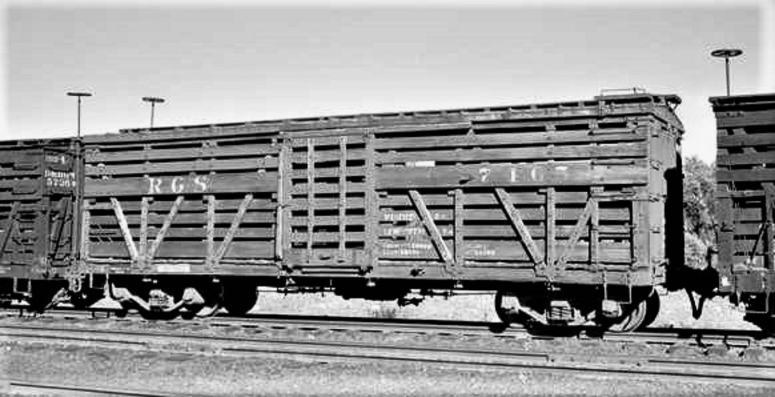
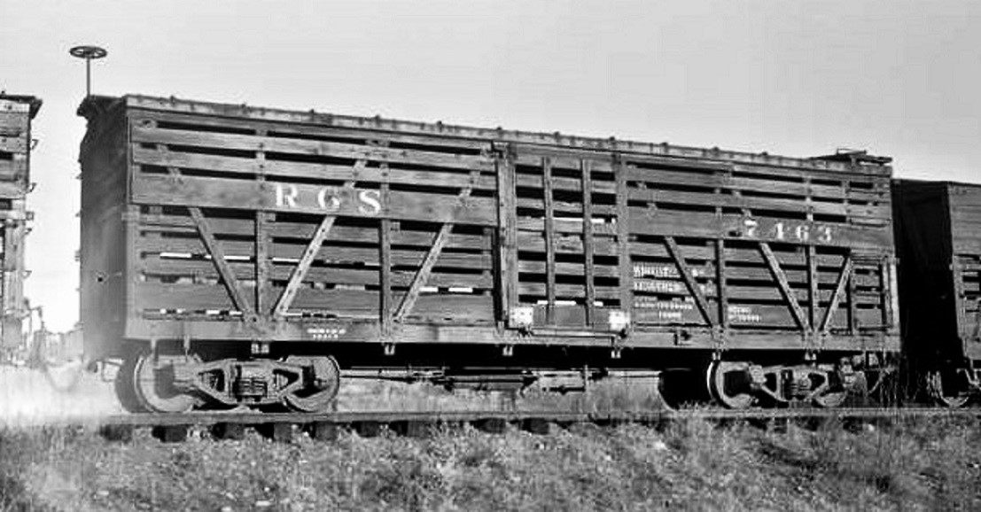
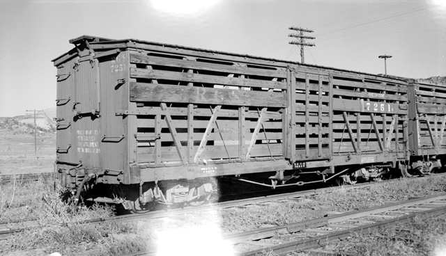
When trying to build a C&S freight car, prototype photos come in handy. Here is my stash:


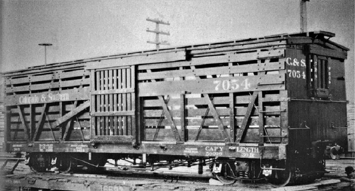
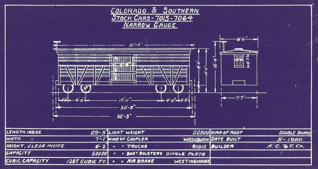
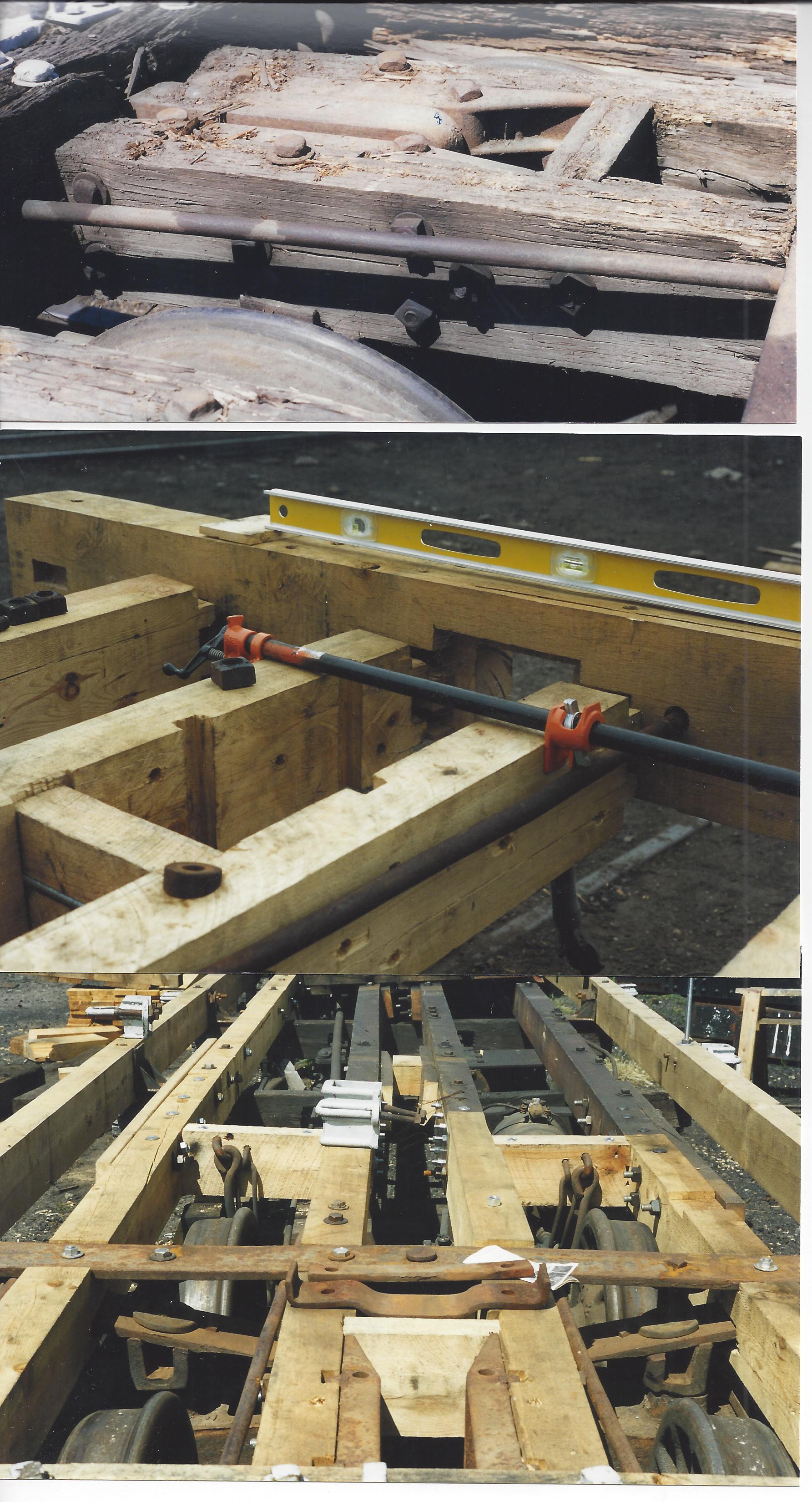
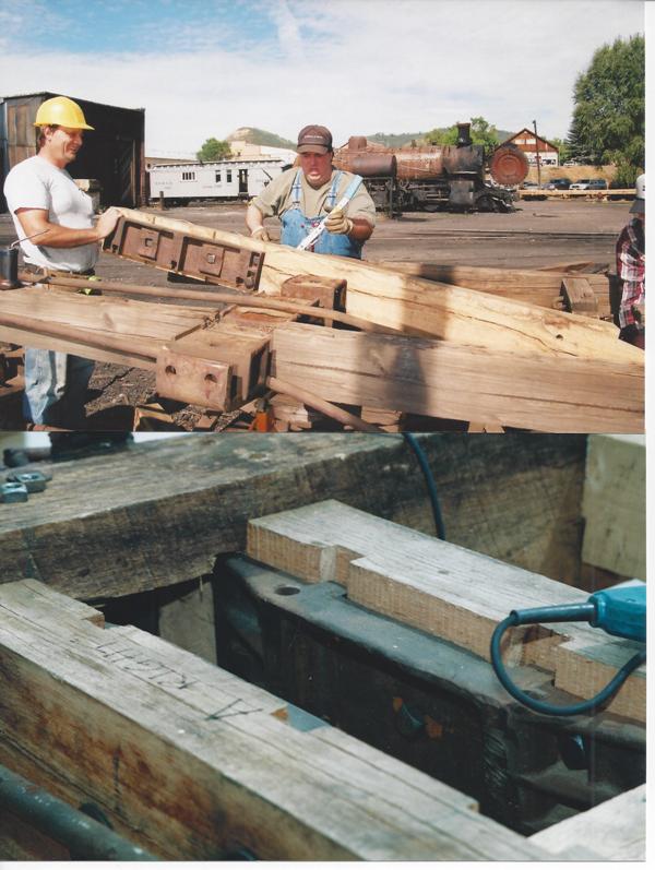
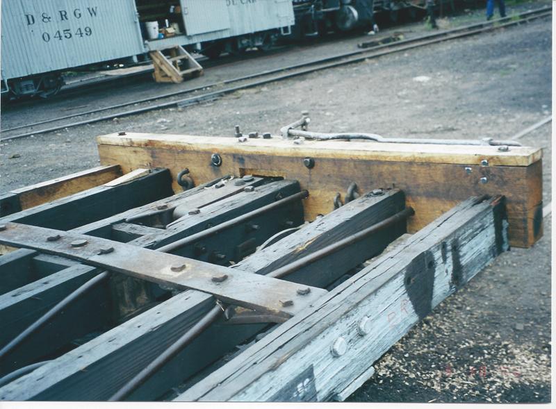
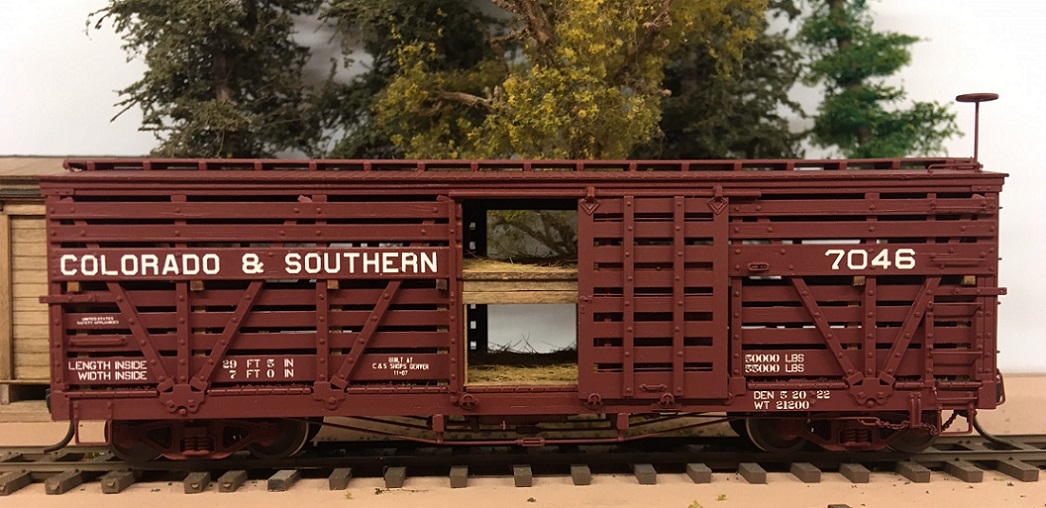
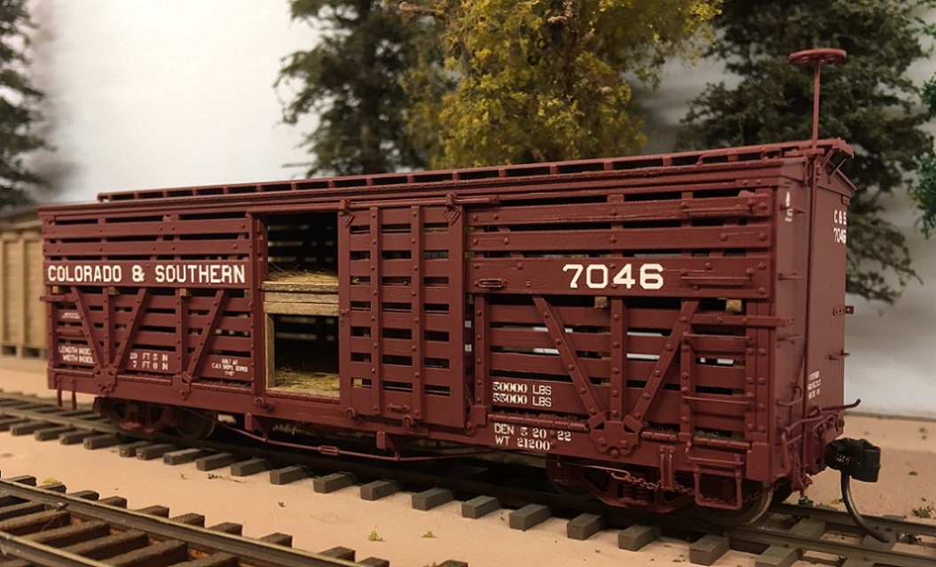
The "Phase 1" stock cars were built in 1900 by St. Charles, by then a part of American Car & Foundry. They are also referred to as AC&F stock cars. They were the last C&S freight cars built by an outside vendor. All subsequent C&S freight cars were built in house at the C&S Denver shops. So, using annoying nomenclature purism, these cars were "Phase 0" stock cars--there were no real Phase 1 stock cars.

As Keith (and most folks) is building a 1930's version, these photos might help:


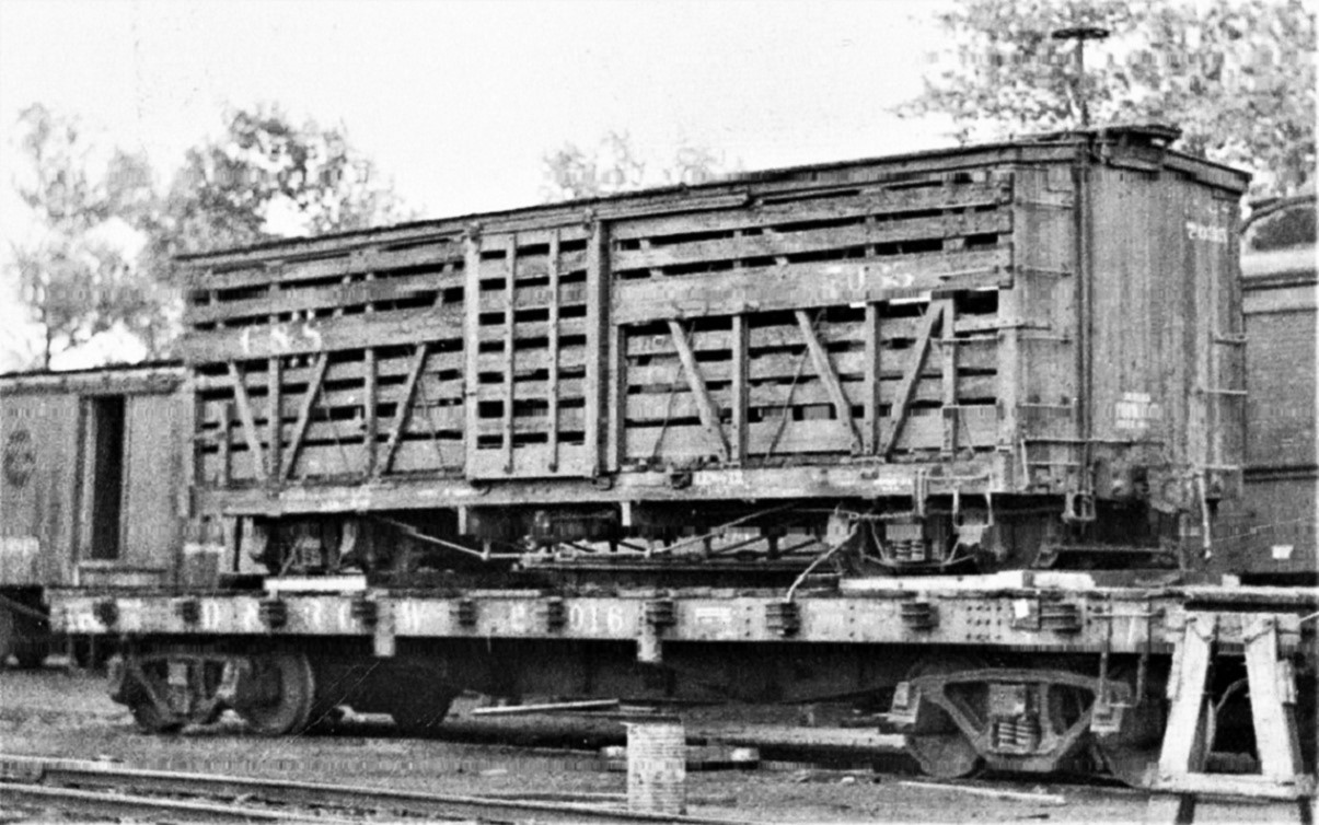
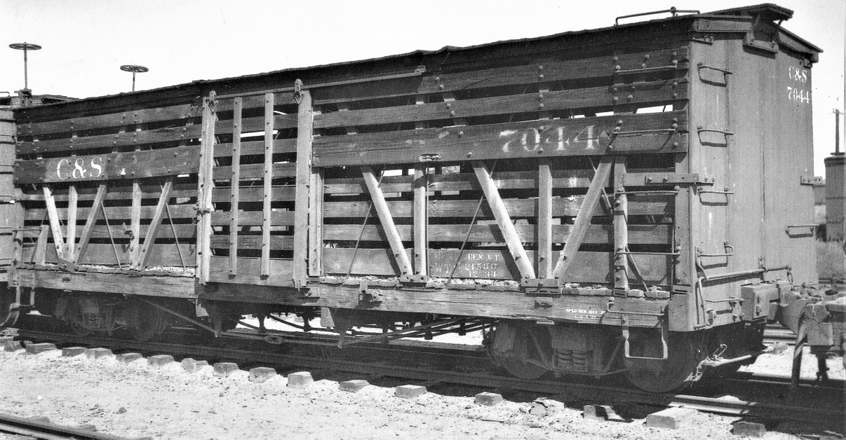
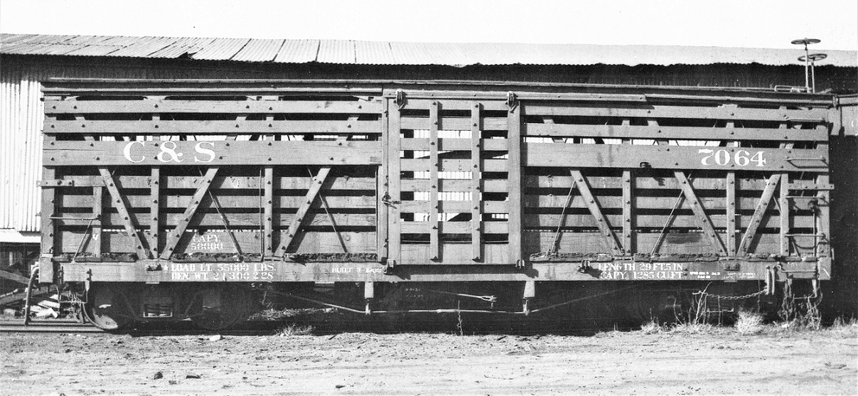
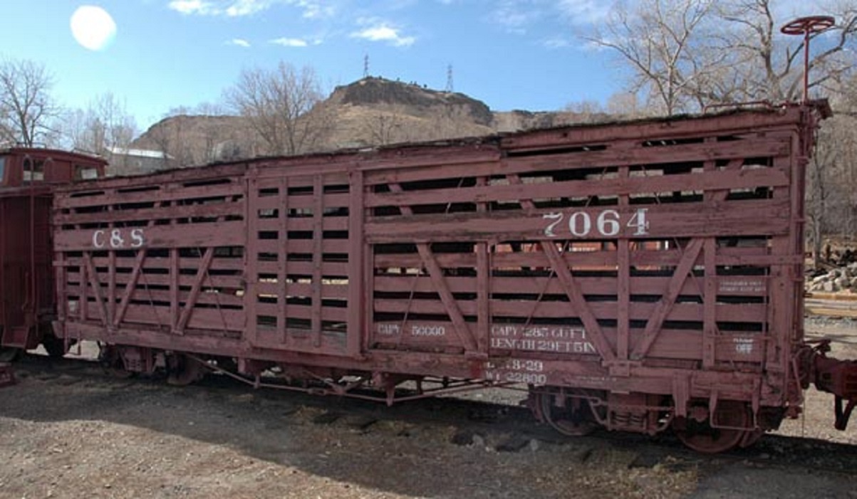
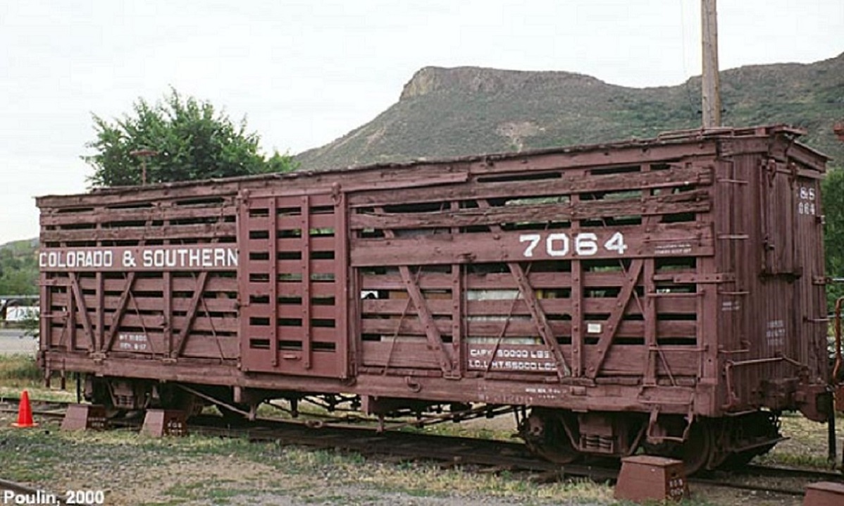
Note that none of the photos show N-B-Ws on the three upper boards to the right of the doors (likely interfered with clearance when doors were opened). Note that 7032 and 7044 only had N-B-Ws for the bottom boards; the 7064 had them on the posts for all the lower boards.

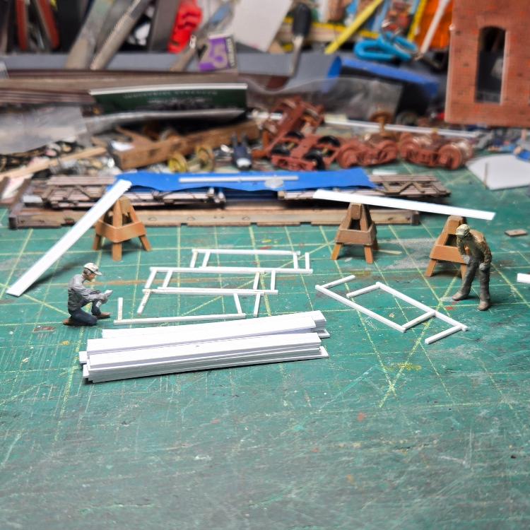
Several years ago, when Bill's kits were first released, I began construction of two 1930s kits. As usual, something interrupted the project, all the parts were put away, then forgotten about in favor of other projects. Perhaps this thread will inspire me to resurrect this project. FWIW, here is how I approached building Bills S scale kits.

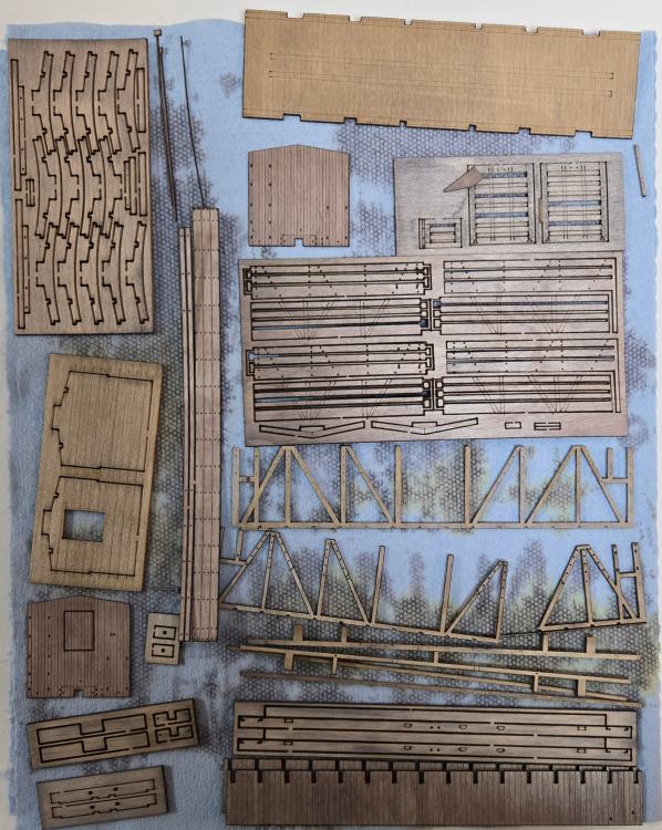
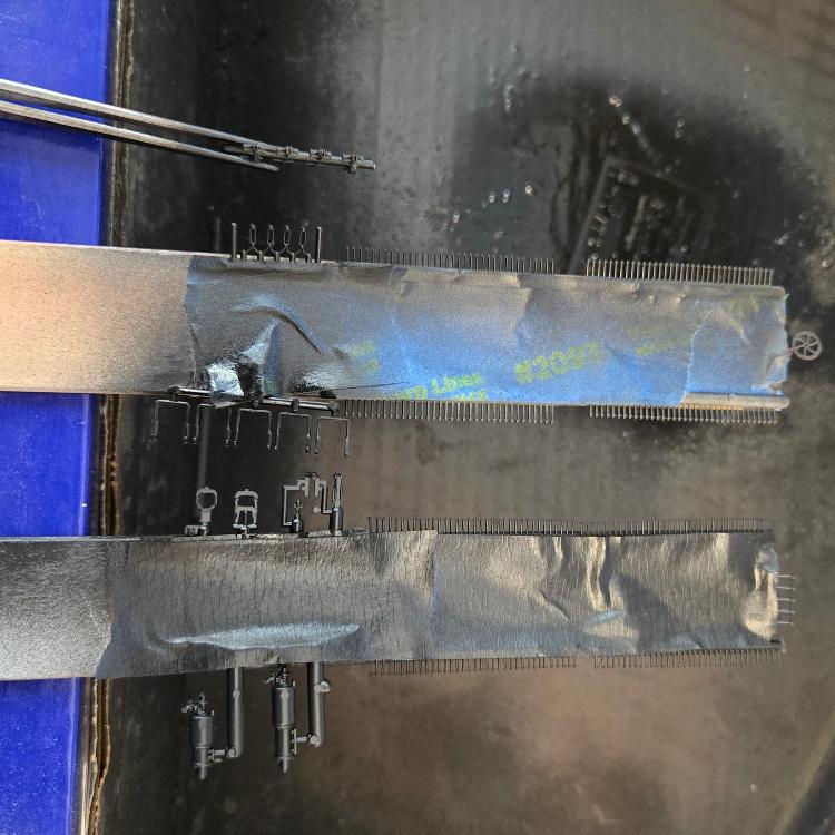
I chose to use Bob Stears method of building laser wood kits. All the major pieces were taped to a large piece of card board and given a liberal coat of Testor's Dullcote from a rattle can, front and back:


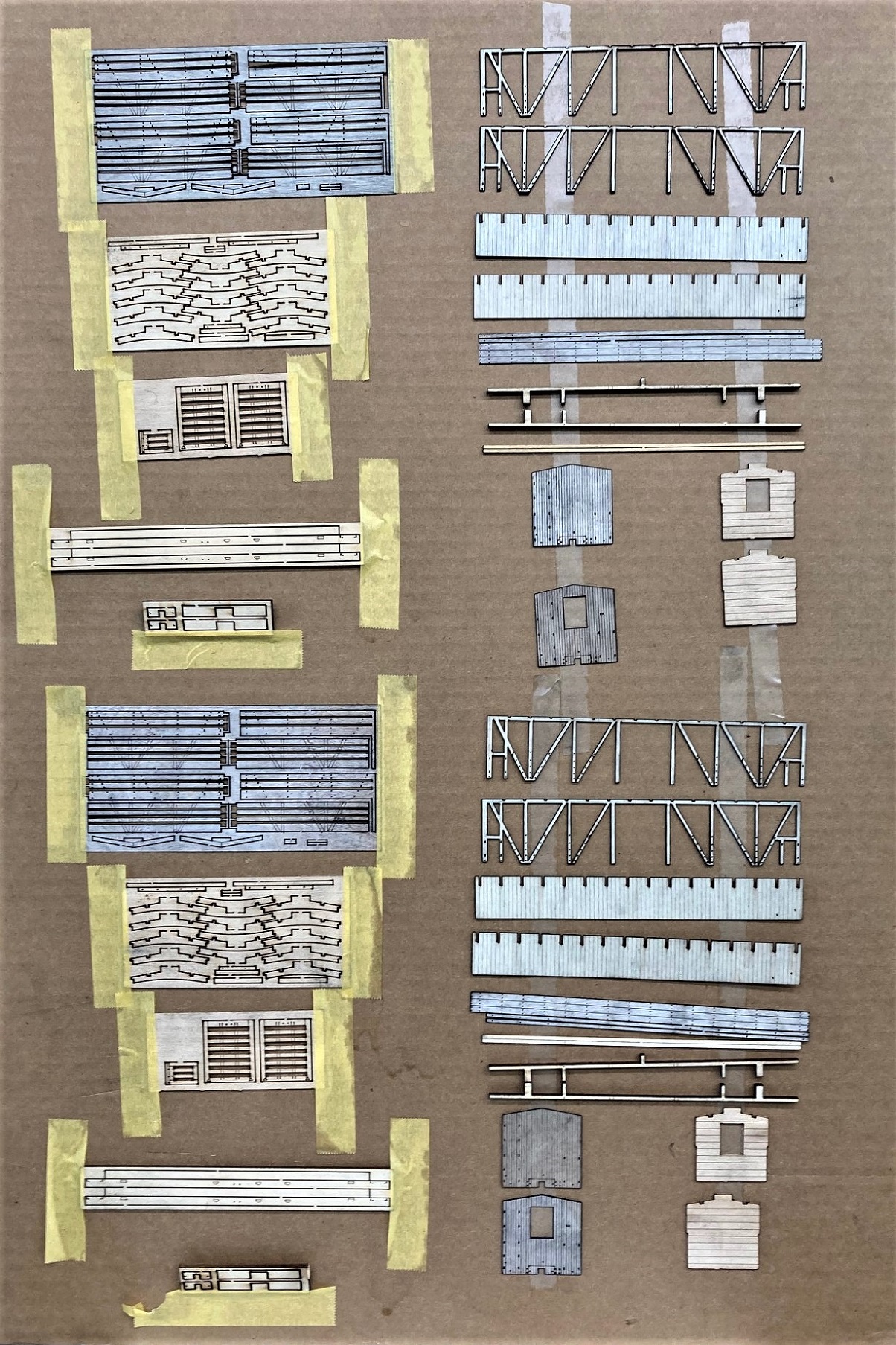
The exception was the floor boards with laser engraved planks--only the bottom got Dullcote, the tops were weathered with black and brown leather dyes in alcohol. The coat of Dullcote allows one to use thin ACC to assemble wood to wood parts and etched brass to wood parts. MEK can be used to attach styrene parts like N-B-Ws to the wood parts.

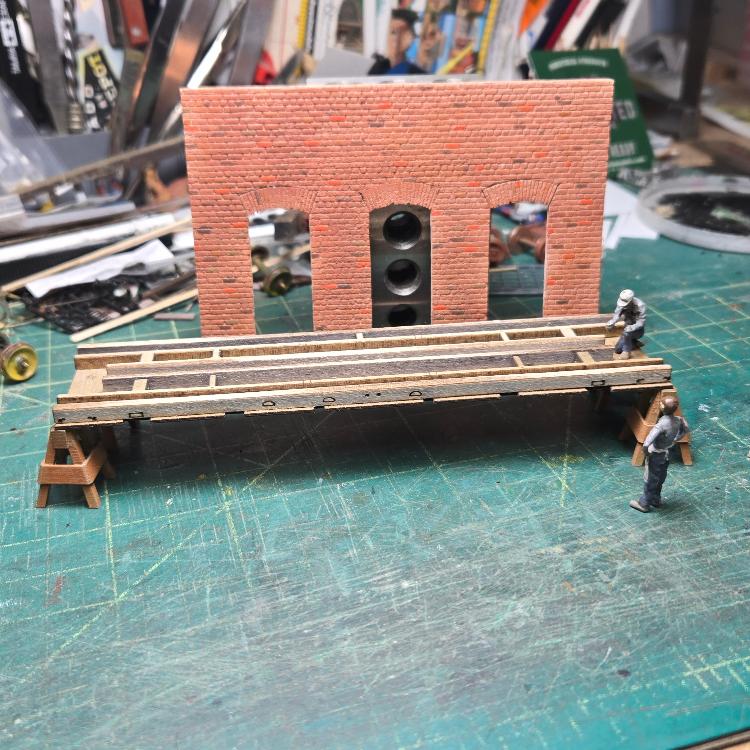
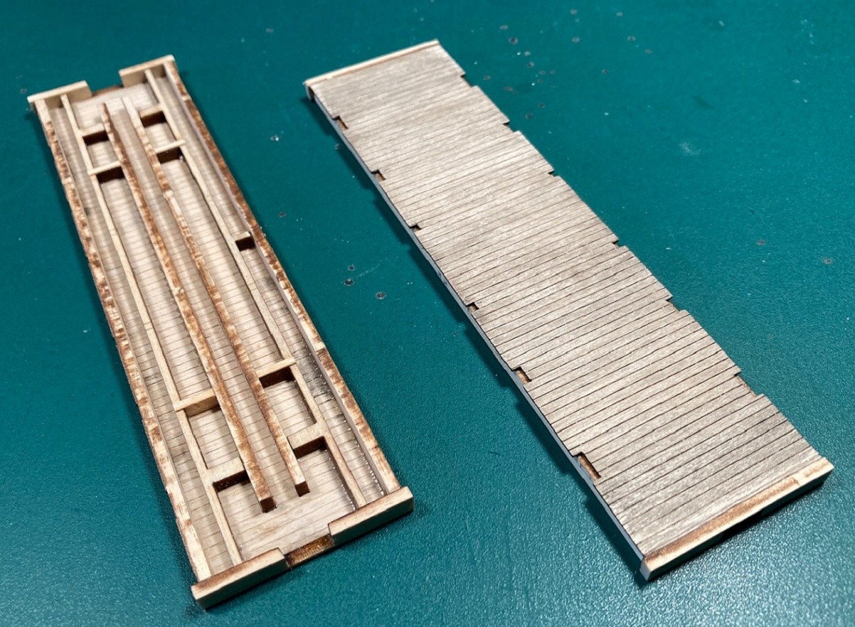
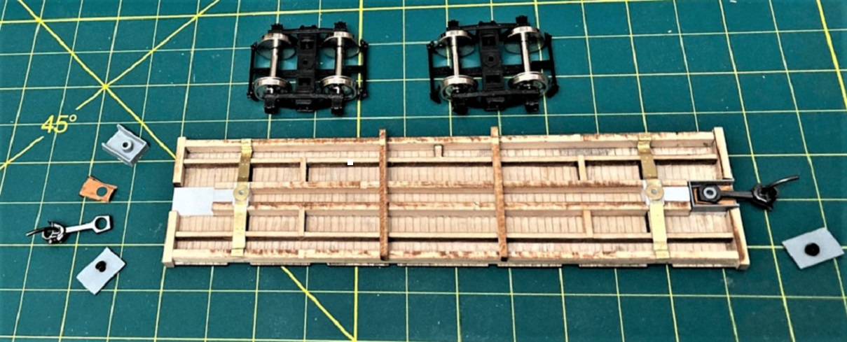
I assembled the basic underframes and flooring per the instructions:


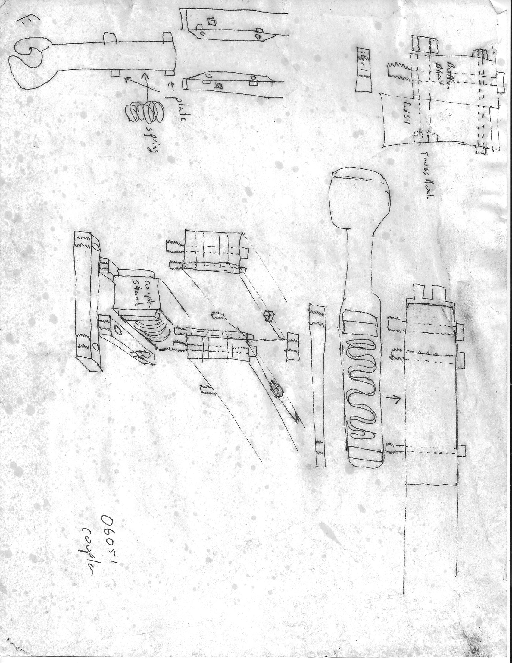
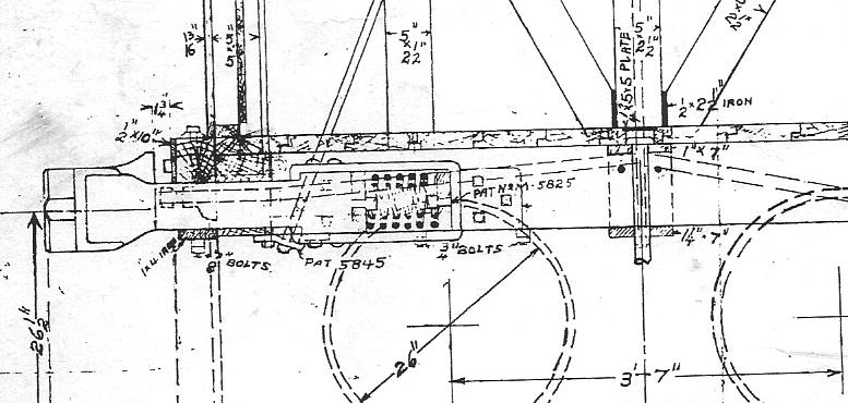
I always like to do the basic heavy handed tasks first, usually bolsters, trucks and coupler mounts that place the couplers at the correct height. Bill makes no provision for mounting couplers, other than an empty space on the under floor and a gap in the end beams.  I use P-B-L coupler pockets that are modified:


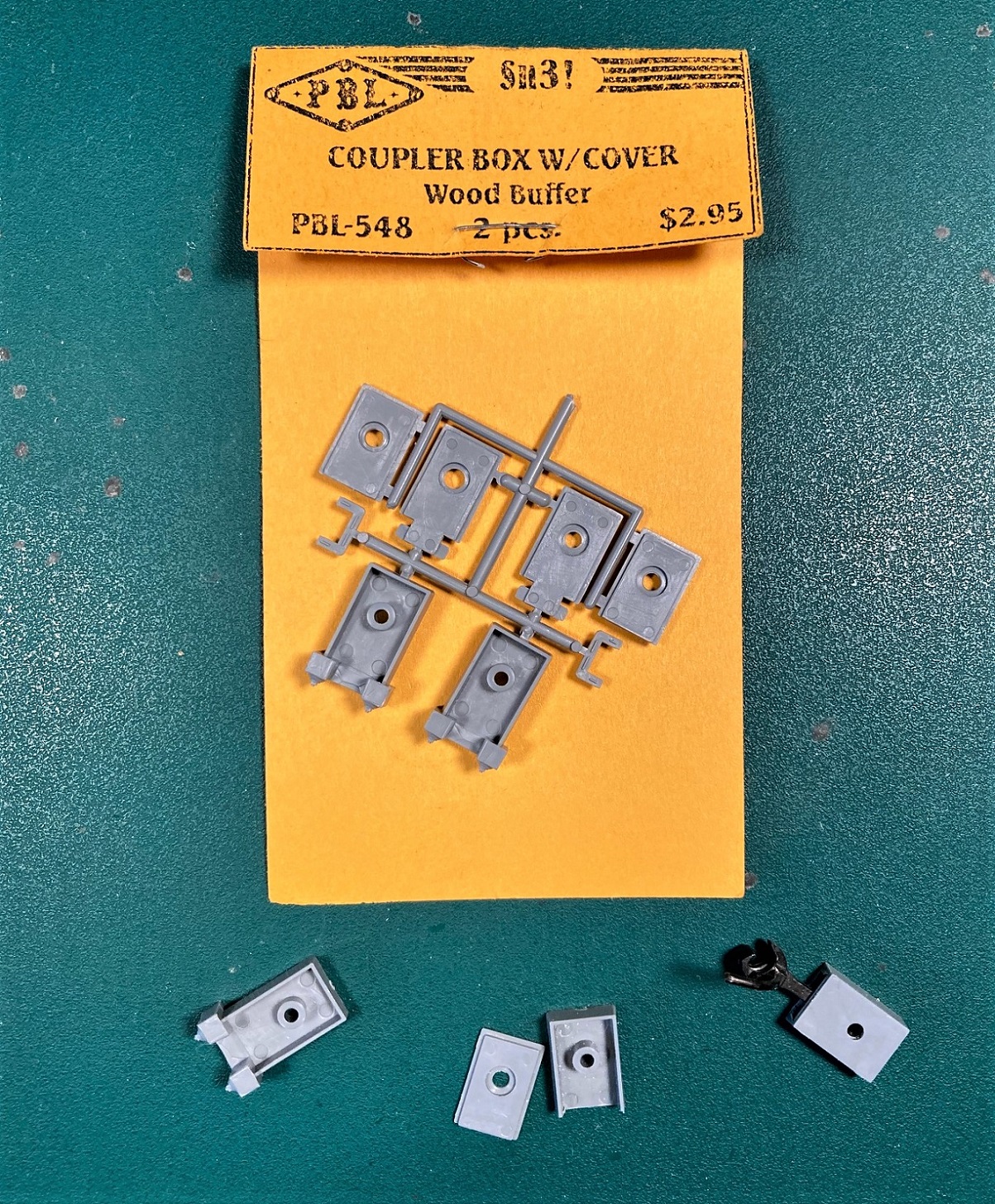
The couple pockets are available from P-B-L online: https://p-b-l.com/, go to online catalog, plastic freight car parts.


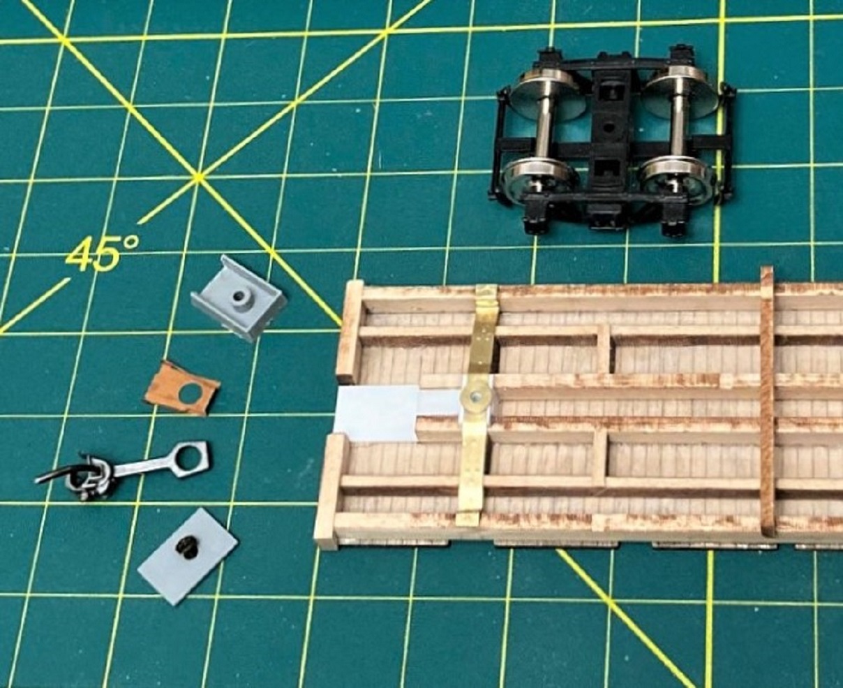
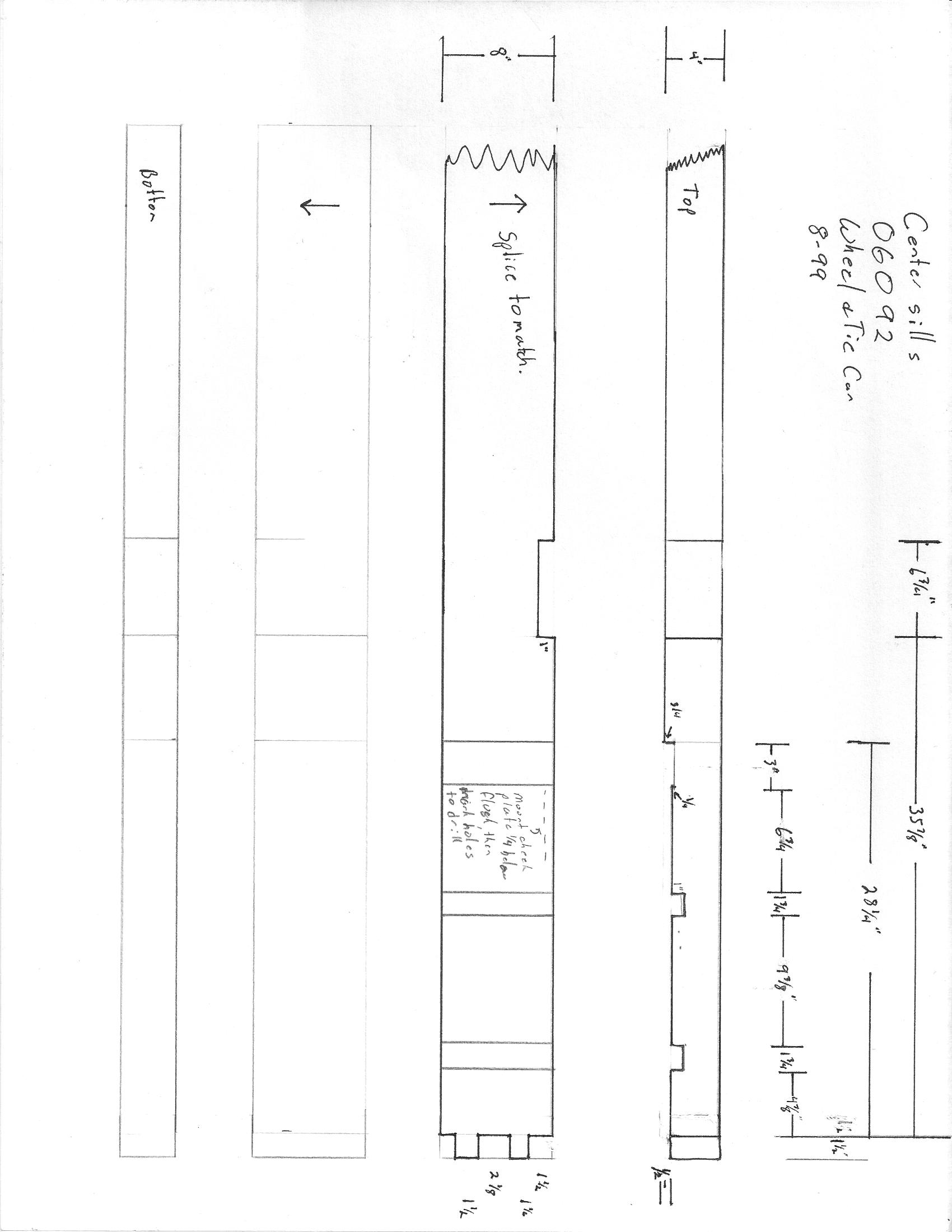
I substituted pieces of styrene of the same dimensions for Bill's wood bolster pad and built up the space between the center sills with styrene, to accept tapped holes for the truck bolster screws. I then formed up Bill's etched brass plate bolsters and attached them to the underframe. As I'm congenitally incapable of bending sheet brass squarely without fold lines, I'm not particularly happy with them. I'll likely build them up from styrene next time. The trucks used are Cimarron Works AC&F 4' arch bar trucks. They were available from Precision Vintage Classis, but with Paul Vaughn's passing, I don't know whether they will every be offered again.

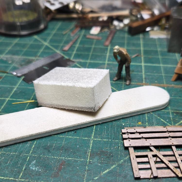
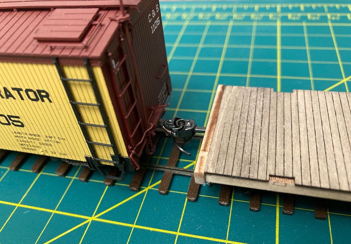
I cut rectangles of 0.030" styrene to fit as coupler pads.  Before gluing the coupler boxes in place, I test fit an end with striker block to ensure clearance:


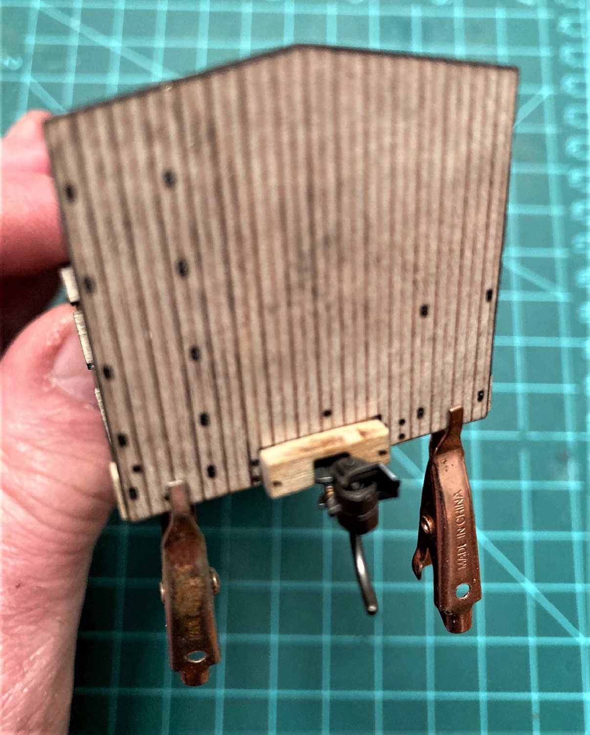
With the coupler boxes glued in place and the trucks mounted, car underframe height and coupler height seemed right-on. These photos illustrate the whole process:


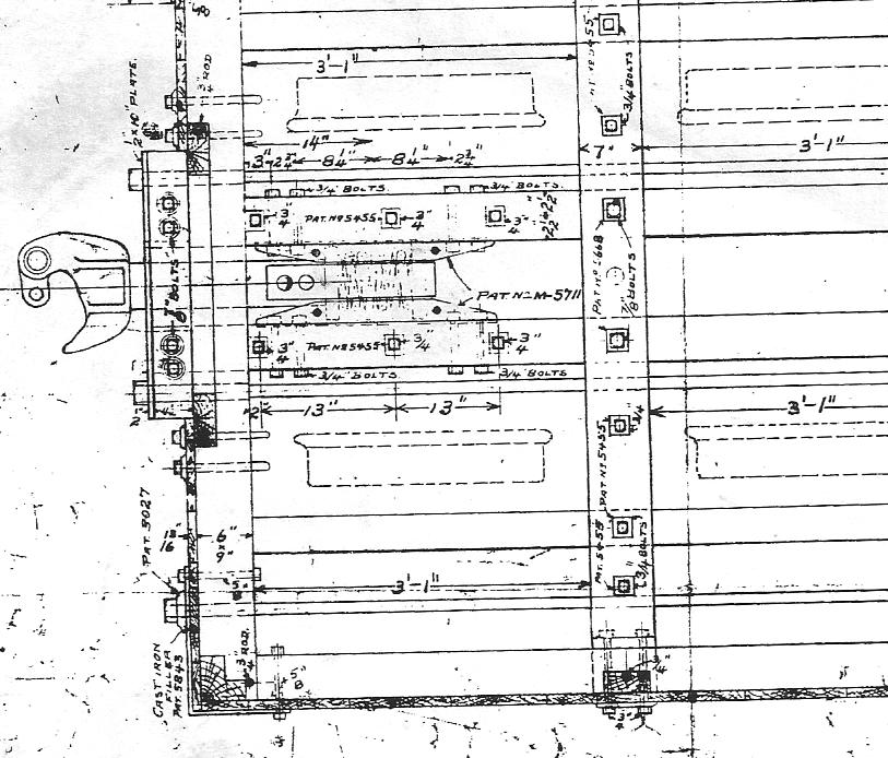
I spent considerable time on the sides. The plywood side framing is confusing--the scored lines for the tension rods is the back side (inside of the framing, next to the cattle or sheep). But the scoring for the tension rods was shallow and incomplete.  Per Derrell Poole's plans, the tension rods were 3/4" diameter, or about 0.010" in S scale. I used 0.010" brass wire, chemically blackened with A-West "Blacken It".

I mounted two blades in my micro razor saw handle. The blades are about 0.005-0.006" thick, so the saw would now cut lines 0.010-0.012" wide. I placed the blade into the laser grooves and cut into the plywood about 1/3 to 1/2 the depth of the plywood thickness and glued in the tension rods with ACC:


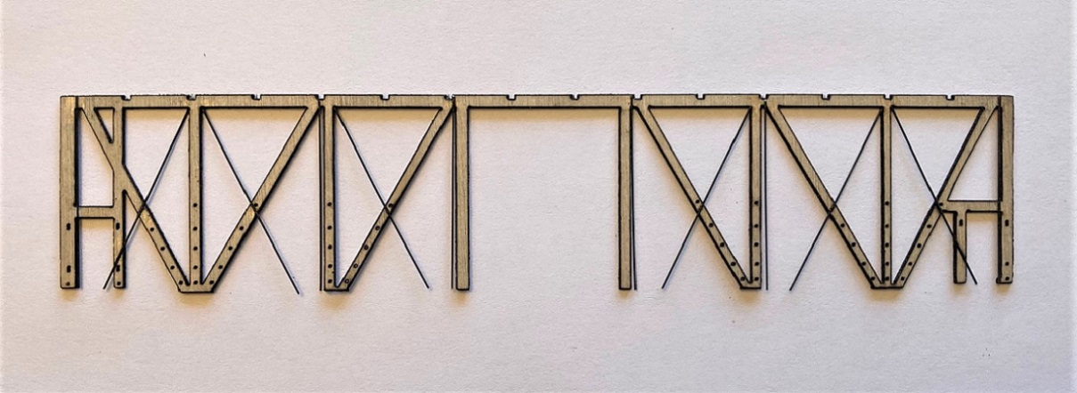
I also cut vertical grooves for vertical tension rods (next to the door posts, corner posts and the vertical posts that were part of the "V" framing. Adding the lower four boards, glued to the inside of the framing, helped secure the tension rods.


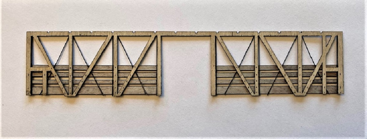
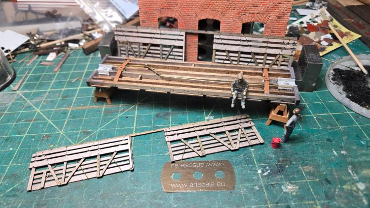
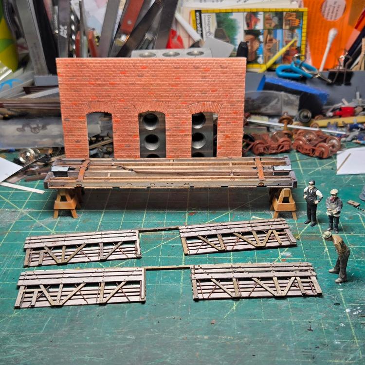
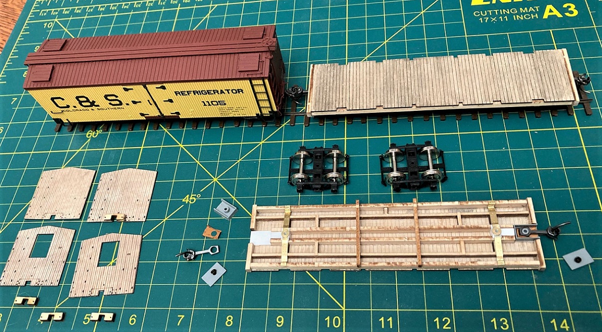
The upper boards came next:


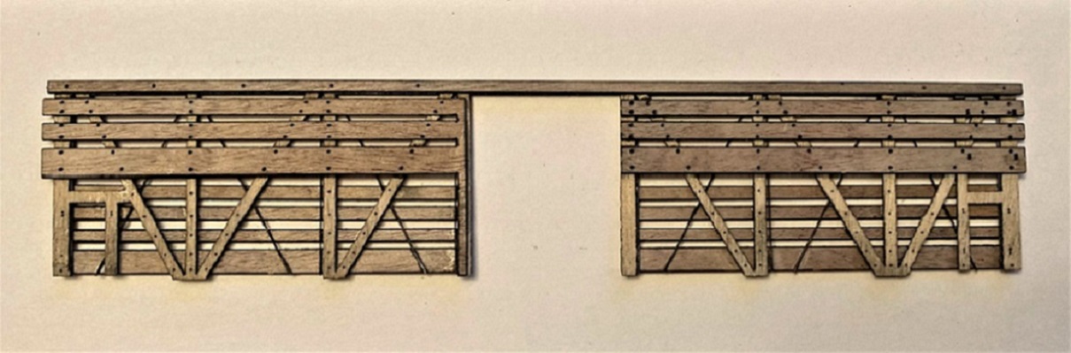
I was careful to glue the left hand upper board assembly to the framing making sure that the laser holes for the NBWs were centered over the vertical and diagonal posts. This left a bit of a gap over the door post. Fortunately this will be hidden when the vertical door-stop post is attached. All the sides need are grab irons installed and about a gazillion small Grandt NBW's.

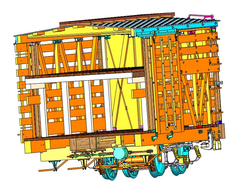
Alas, this is as far as I got before pausing the project. Should I continue along with Keith and finish the 1930s stock cars, or get to work on the first decade version of the kit, as in the first photo above??


Jim Courtney
Poulsbo, WA
Reply | Threaded
Open this post in threaded view
|

Re: Leadville Designs C&S Phase I Stock Car

Chris Walker
Since when did the C&S mirror the D&RG underframe construction?
   
In 1994 I videoed the entire underframe of the existing C&S Stockcar at the CRRM, but I cannot view any of that footage, nor recall any splices under it.

UpSideDownC
in New Zealand
Reply | Threaded
Open this post in threaded view
|

Re: Leadville Designs C&S Phase I Stock Car

Keith Hayes
Mr. Walker, I stand corrected. I just assumed, and well here I am.

Tony, I think I used the wrong term: this lot is sharp as a carman's chisel, and one needs to take care with the lexicon.

Indeed, cheek plates are those metal castings on either side of the drawbar shanks. I meant to refer to the 2x that is bolted through the center sills holding the diagonal spliced together. But, St.Charles/AC&F/ 9th Street must have done it differently.

I am trying some new methods as I shared earlier. The kit has a bag of goodies in resin, brass and styrene. The brass was lightly tarnished, so I cleaned it in a bath of 50:50 vinegar and water. I left the brass in the wash for 10 minutes and let it air dry overnight and apply Mr. Surfacer the next morning.

I also rigged the styrene and Delrin parts on paint stirring sticks (they are free) and gave them a coat of black primer as well. I am planning to follow this with some C&S red and maybe a sponge of rust.
Keith Hayes
Leadville in Sn3
Reply | Threaded
Open this post in threaded view
|

Re: Leadville Designs C&S Phase I Stock Car

Lee Gustafson
In reply to this post by Jim Courtney
Jim,

I vote for the 1930’s version build. Looking forward to either version you build. Thanks for sharing your work.

Lee Gustafson
Reply | Threaded
Open this post in threaded view
|

Re: Leadville Designs C&S Phase I Stock Car

Keith Hayes
In reply to this post by Jim Courtney
Thanks to all of Jim's tips and some weekend evening hours,  I have almost caught up to his progress.

When we left the project,  I had cleaned/ etched the brass parts and primed all the bits and bobs. This was followed with a coat of brown and Rust paint. The stain on the wood was also touched up.

For the underframe,  I followed Jim's tip and ordered some coupler boxes from PBL. Too bad the buffer block is so small for this car. Oh, we'll, into the scrap bin! I installed the shim and styrene block under the bolster,  too.

PS, want a source for and inexpensive and indispensable tool? Talk to your wife, or go get a manicure. When the manicure is over, ask the nail tech for the disposable files. They are going to throw it out anyway. This one has four different grits and has been super on wood and styrene. Also, if your hand ends up in the model Pic, we will all thank you!

I also started to build up the sides. These look easy, with all the laser bolt oles and alignment lines. Well, follow the plans closely because they have to be just right to overlap the ends and be spaced correctly vertically. But that will be a problem to solve for the next step.

Lee, this is going to be a 30s car. The question is, do I make it a sheep car? 🐑
Keith Hayes
Leadville in Sn3
Reply | Threaded
Open this post in threaded view
|

Re: Leadville Designs C&S Phase I Stock Car

Jim Courtney
Did someone say sheep car?


If Keith choses a double deck car, be aware that the upper deck construction was different than on D&RGW double deck stock cars. There were pairs of interior vertical 4x4s, length the distance from floor to the top of the top board of lower/inner side boards. They were located just toward the door, next to each of the vertical frame posts, and just outside the door posts. Atop these inner posts, 4x4 upper floor joists were attached (I don't know if there was a center post). The actual upper deck flooring was 2-byes, that ran longitudinally the length of the car interior. The door openings had different framing than D&RGW stock cars.

The interior posts and joist ends are best seen in these two RGS "Miller" phase 3 stock cars:


In a long ago thread, Jim McGee shared the cars numbers of the 1900 stock cars that ended up double decked, 17 in total:
C&S numbers 7015, 7017, 7019, 7021, 7022, 7024, 7025, 7032, 7034, 7038, 7039, 7042, 7045, 7048, 7049, 7050 and 7060.

Keith, if you model a double deck car, be sure to leave the doors open so's we can see your handiwork.

Speaking of doors, the vertical braces that attach to the horizontal slats of the side doors, that Bill provided in the kit, are very nice brass etchings. Unfortunately, the brass pieces are very thin and don't match the thickness of the braces on the phase 2 and 3 stock cars. Worse, the etched bolt heads don't match up with the wooden slats. I plan to make mine of strip styrene, with Tichy rivet heads.

Taking stock, I think I need to finish up the coal car / flat car project before getting back to stock cars. I had planned to have them finished up, painted and lettered by early spring. But as John Lennon wrote, "Life is what happens when you're making plans" . . .
Jim Courtney
Poulsbo, WA
Reply | Threaded
Open this post in threaded view
|

Re: Leadville Designs C&S Phase I Stock Car

Chris Walker
Jim Courtney wrote
Did someone say sheep ...?

Droving some your way right now,  Keith,
No, that is not on the Gilpin Tramway; but Keith Pashina would be at home here....

Joe Wallace Photo
Danseys Pass Rd.
UpSideDownC
in New Zealand
Reply | Threaded
Open this post in threaded view
|

Re: Leadville Designs C&S Phase I Stock Car

Lee Gustafson
In reply to this post by Keith Hayes
Keith,

I trust you would not pull the wool over my eyes. Looking forward to your sheep car build.

Lee Gustafson
Reply | Threaded
Open this post in threaded view
|

Re: Leadville Designs C&S Phase I Stock Car

Mike Trent
Administrator
In reply to this post by Jim Courtney
Wow, Jim! Great work.
Reply | Threaded
Open this post in threaded view
|

Re: Leadville Designs C&S Phase I Stock Car

Al Pomeroy
Keith,
Note also that the upper deck is not evenly spaced with the lower. I determined this from a Photo by Mal Ferrel in the RGS series books
and built my first prize model that way. here is a section view from the 3d cad.


Al P.

Also note the bull boards which are in my model but not used in the DD version.
Reply | Threaded
Open this post in threaded view
|

Re: Leadville Designs C&S Phase I Stock Car

Jim Courtney
In reply to this post by Chris Walker
Further musings about the LD stock car assembly:

Weighty Issues:

Consideration should be made as to adding weight to the car prior to adding the carlines / roof.

My wood LD coal cars, when the body was complete, weighed in at only about 1.5-1.7 Oz., even with the cast brass bolsters. I prefer car weights of 3-3.5 oz. for Sn3. The obvious solution for the coal cars was to hide a weight under a coal, ore or lumber load, but I had planned on these cars always being "empties".

I ended up adding thin lead sheet cut into strips to fit between the two center sills and between center and intermediate sills. This had to be done before adding the needle beams and brake rigging. The coal cars ride so close to the ground that these weights weren't really visible. This got the car weights up to about 2.6-2.7 oz. Better, but not ideal.

In starting the build of the unfinished LD stock cars, I had planned to add irregular, circular layers (one or two) of lead sheet and paint them dark brown. They would be glued to the inside of the car floor from over the bolsters to near the doors, to represent piles of manure. A little S scale dirt and straw over them would pretty much hide them when viewed thru the slats.

It is a shame that Shapeways can't print Keith's flat cows and sheep in lead!

Sanding blocks:

I, too, find manicure sanding blocks very useful. If you feel like getting a manicure isn't very manly, you can get these very inexpensive ones from Amazon:
https://www.amazon.com/Buffers-Smoother-Polisher-Fingernail-Shinning/dp/B0CLXGPLQL/ref=sr_1_6?dib=eyJ2IjoiMSJ9.4p6YsQONc-l3lZUkb70Lq7QN5Tl3rBsrrq1vOxjBIQEPa0O7AAAAJgyNZ_6ChDSkm-av4LkHP9lpfZJEzT873TZ61NUcGAt0FBJCVjiEyKvq9L5TggUf4Eg4m4QmrLtbXCtNJh4w9SMMeCUX7SQg7UA0qLwcDYb5XERCLDVuakKHhwChaU66zDnVqim_vIdbfGwMW_o2Pqg4g3TzWU8RYoBUgzlXohBiwKV3LFIoEv4Jjq0ZM7zv6_Y_RjzirB9Wld8xEe_BarUDwqq_ttN23BUp9z2cmDUIMEP-7e6bdFg.1nazyloE4fwOQbM5UF7c4Mu45Defwq_gLj4lwjwX_to&dib_tag=se&keywords=Nail%3B+buffer+block&qid=1751348873&sr=8-6
Jim Courtney
Poulsbo, WA
Reply | Threaded
Open this post in threaded view
|

Re: Leadville Designs C&S Phase I Stock Car

Keith Hayes
After the distraction of operations and some 3d printing, I returned to the shop to relax and drill some holes. About 200.

Jim's tips are very handy. I ordered the coupler pockets from PBL and installed them as suggested. I also installed the train line and held it in place with some U-shaped wire.

I may have built the sides incorrectly. I did not start with the fascia as recommended, but installed the slats, attempting to line up the bolts and laser guidelines instead. Note to future me when I build the second car, the bottom board is held up from the frame some.

Al, thanks for the drawing. I have no doubt that it is correct,  but the clear height at the upper deck appears small. I would think sheep need at least 42", and that cannot be more than 30". Chris, can you please confirm?
Keith Hayes
Leadville in Sn3
Reply | Threaded
Open this post in threaded view
|

Re: Leadville Designs C&S Phase I Stock Car:Sheep Statistics.

Chris Walker
Depends on the breed, and the feed, Keith. My two sheep out eat five goats.
My Texel wether with full clip is 29" and the ewe is 26". The neighbour's Merino are taller, 32" for a Ram.   I saw some sheep up at Animas Forks once, and they were smaller, lighter than any I've seen here.

UpSideDownC
in New Zealand
Reply | Threaded
Open this post in threaded view
|

Re: Leadville Designs C&S Phase I Stock Car:Sheep Statistics.

Al Pomeroy
Keith,

found a picture in my collection that shows where the cross beams were located, validating the High second deck.


Al P.
Reply | Threaded
Open this post in threaded view
|

Re: Leadville Designs C&S Phase I Stock Car:Sheep Statistics.

Keith Hayes
Al, I think you have an extra layer of structure. I believe a timber "rested" on the top inner board,  one side or the other of the exterior vertical post. Inside, on both ends a vertical post supports the timber. You can see this in the shadow of some of the pics--these are very shy parts. I believe these were 4x4s.

Someone else has posited that the upper deck planks ran the length of the car, not across it as the floor below. These could be 12' long boards, staggered, or not, 2x12 or 3x12. The question is, was there a layer of flooring above this that was laid perpendicular across the sub floor?

According to my measurements of a PBL PIII stock car, that would provide 34" to 38" at the top deck, a bit more spacious,  if for no other reason than to accommodate the poor sod that had to muck out the car after unloading and set fresh bedding prior to loading. This also better aligns with the bottom of the lumber door on the A end of the car--I figure the sills of that dor is 2" to 3" above the door itself.
Keith Hayes
Leadville in Sn3
Reply | Threaded
Open this post in threaded view
|

Re: Leadville Designs C&S Phase I Stock Car:Sheep Statistics.

Keith Hayes
How to add a second deck. The hard way.
Keith Hayes
Leadville in Sn3
12