Platte Canon progress report
12


12
|
This post was updated on .
Outstanding work, John.
I think you’ll be much happier with the brass tension bars; that’s one thing I do differently if I built another one. (They styrene in that dimension is just too bendy.) I look forward to seeing your progress. Cheers, Jeff. |
Re: Platte Canon progress report
|
Thanks, Jeff. Despite my brave words, I may yet lose my nerve for making all those pin assemblies and copy your clever method instead. I get very excited about solving a fabrication problem, but then I have a tendency to lose enthusiasm for doing it N times, especially given my very limited time for model work. In returning to this after many years, I'm trying to just have fun… but then I think how nice the bridge might be with all those pins and rods to look at.
Cheers, John
John Greenly
Lansing, NY |
Re: Platte Canon progress report
|
Well, I got all the truss rods and floor beams manufactured for my bridge. Luckily I realized early on that a pin-connected truss requires rather tight tolerances, both accuracy and precision in fabrication in order to end up straight. I made a master of each type of rod and then transferred dimensions to all the others. The danger is that this way any inaccuracy in the master dimensions adds up across all the duplicates and would pull the bridge out of shape. I have now a great appreciation for how well the real bridges must have been manufactured. Here are a couple of photos of my first test assembly of the trusses. Nothing is holding it in position except the pins, so this was to see how straight it would want to stand without any external coercion. The bridge is just resting on the ends of the girders, the deck is resting free on the bridge floor beams, and the U-bolts that connect the rods to the floor beams are just friction-fit, not securely installed. But it seems to look pretty good. The plastic girders unfortunately did not turn out perfectly straight, and were alarmingly floppy until all the connections were made. But now, especially with a load on it, the bridge is amazingly rigid. Trusses really work!! Now that I have it together, I am quite reluctant to take it apart again. I didn't anticipate how difficult it would be to assemble, even though everything fit fine. I really could have used an HO-size bridge crew to help hold all the bits while the pins went in. Talk about a three-handed job, this is about an eight-fingered job, and there isn't room enough for that many full-scale fingers.
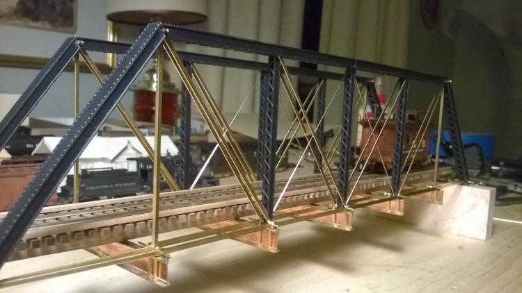 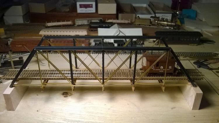  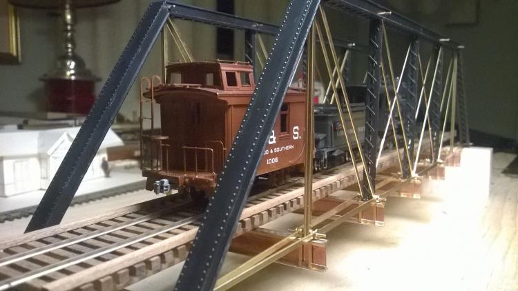 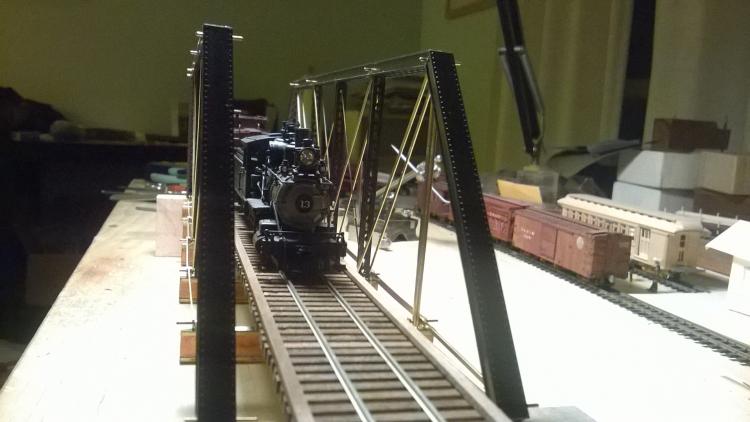 Originally I thought I would not pin-connect the top chord. But after a couple of attempts to do it an "easier" way, I realized that just going ahead and using pins is simpler and better in several ways. The first two photos are before I pinned the top joints at the outer two vertical compression columns. I was just going to glue in the tops of the diagonal rods there, but I realized that to make it come out really right that would have to be done with load on the bridge so that the floor beams would hang on the U-bolts, and then get those rods adjusted just right to keep the center pin of the bottom chord level with the rest, and it was at this point that I decided to just go ahead and pin them. The other three photos are with all the pins in (I'm not bothering to pin the top center connection of the stabilizer rods (the thin ones with turnbuckles), they have no load on them so can just float at the top. The bridge likes the weight of the locomotive on it, it brings everything into very nice straight lines. This is a 6-panel bridge like the Waterton bridge, but I decided to copy the different rod connection arrangements at the pins as on the Deansbury bridge. The Central Valley lace girders make a pretty good approximation of that bridge after reducing the depth of the section from the original dimension. I'm having second thoughts about the lace-girder vertical compression columns though, and I might decide to replace them with simple I-beams as appears to be the case with the Deansbury, Floyd Hill, Forks Creek, Buffalo, etc. C&S bridges. Now I have to decide how to do all the cross bracing at both top and bottom. I'll use small I-beams across the top as Jeff did on his bridge. Got those ordered from Special Shapes last week. Then I have to get out the rivet embossing machine I made 40 years ago and make up various plates and gussets, and then there are the bridge shoes…. And then I need a layout to put it on. Cheers, John
John Greenly
Lansing, NY |
|
Great looking bridge there, John!
FWIW, Tichy sells packets of rivet plates: https://www.tichytraingroup.com/Shop/tabid/91/c/ho_nbw--rivets/p/8277-truss-pin-plates/Default.aspx . I had some issues with temperature expansion on my bridge, although I think it’s because my track is on a curve which pushes out slightly on hot days. I ended up having to leave one set of the tension beams on the bottom (inside of the curve) free-floating. Cheers, Jeff. PS: a couple of my firemen are fighting over the new shovel….
|
Re: Platte Canon progress report
|
In reply to this post by John Greenly
John,
Your work is excellent. The quality of work and engineering as they apply to model building and the prototype structure are outstanding. How many fingers and hands do you have ? ;-) Lee Gustafson |
|
Platte Cañon models sells extra hands and fingers for model building.

"Duty above all else except Honor"
|
Re: Platte Canon progress report
|
In reply to this post by Jeff Young
Thanks, Jeff and Lee, for the encouraging words!
I'm having fun with this because it's teaching me how the real thing works, which is what interests me most. This is reminding me, too, that something that does its job in the most efficient way almost always seems to look really nice to me. As to the fingers, I'm happy to say I still have the regulation number after all these years, and they mostly still work. Nevertheless- South Park, do they sell those extras in six-packs? Speaking of how things work, Jeff's comment about thermal expansion is something I started to look into. As I'm sure you all know better than I, there are all sorts of rail expansion joints used to accommodate movement of bridges, and in various other situations. I haven't found any evidence yet in photos that the C&S bridges used such things. Maybe these bridges are not long enough to need them. I looked at the standard-gauge steel through-truss near my home, which is about the same length as my bridge, 95 ft. The welded rail there just goes right on through the bridge, no provision at all for expansion that I could see. That bridge is straight but a curve starts just outside one end. Various combinations of hinged (pinned) and sliding-plate bridge shoes are used to allow movement of a bridge itself without stressing the abutments. I'm looking for good pics of the ends of the C&S bridges to see how they were fitted out. I found one of Deansbury that shows clearly a pinned hinged shoe at one end, but can't see the other. Then there is one of the bridge near Floyd hill that shows a flat plate, presumably sliding, shoe, but again can't see the other end. These photos are on other threads here, I can repost them if anyone would like. Another question: does anyone know how- or if- a wooden bridge deck like mine would be fastened down to the floor beams? Seems as if there would be some connection to avoid sideways movements, but a solid connection would cause some additional longitudinal stresses because of differential expansion of the steel bottom chord rods and the wooden deck stringers. This would also be a more serious issue with a bridge on a curve. Any advice out there? many thanks, John
John Greenly
Lansing, NY |
|
Hi John,
I don't remember if this picture was already posted or not, but this is the model I used for my bridge shoes (from the Mill Gulch bridge near Waterton): 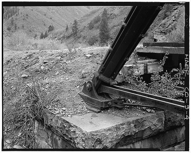 (http://www.loc.gov/pictures/item/co0019/) Cheers, Jeff. |
Re: Platte Canon progress report
|
Thanks Jeff, yes,
I've been using this set of photos, and this one is the best photo of a shoe I have seen, with the pinned hinge and probably also freedom to slide horizontally for expansion. The particular configuration is specific to the cast end on this bridge's unique girders, but I think you did a nice job of adapting it to the standard lace girders. I may do pretty much the same thing if I can't find a really good picture of one of those. This is the best I've found yet. You have to look at max zoom and it's pretty blurry. I think the far end might be different, but really can't tell. http://digital.denverlibrary.org/cdm/fullbrowser/collection/p15330coll21/id/6942/rv/singleitem/rec/13 Cheers, John PS I hope your firemen don't come to blows over the shovel. I'm looking for maybe some tin shimstock for blades so they would look right without being painted, and if that works out I'll make you another one for peacemaking in your enginehouse.
John Greenly
Lansing, NY |
|
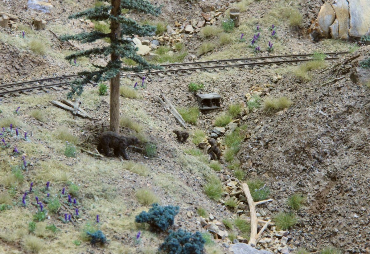
A couple more scenery shots:
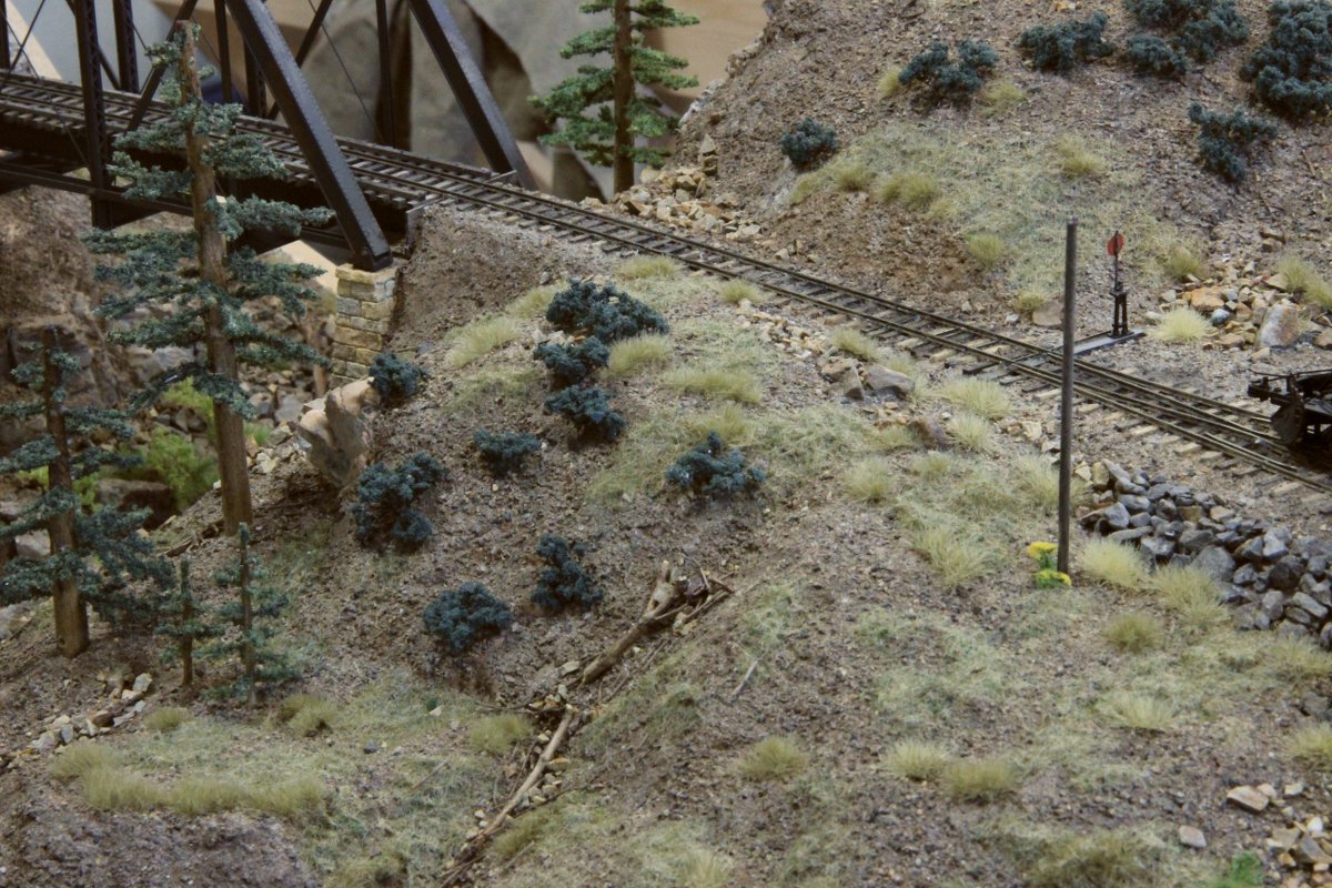 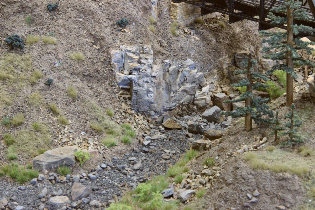 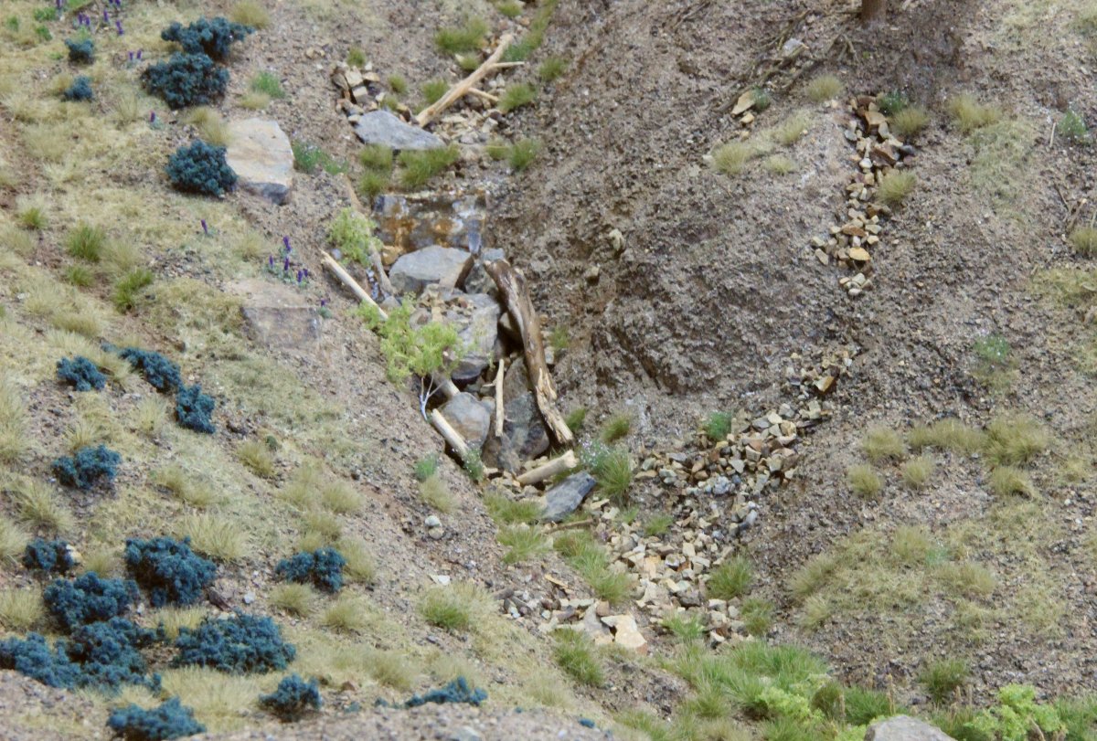 
|
|
Excellent work, Jeff.
You need to spend some time at Leadville next year!
Keith Hayes
Leadville in Sn3 |
Re: Platte Canon progress report
|
Nice. Thanks for posting more pictures. Looking great.
|
Re: Platte Canon progress report
|
In reply to this post by Jeff Young
Jeff,
I really like the purple wild flowers. My sister-in-law has a 40 acre place near Conifer, including a meadow with various blooming weeds and flowers. There is a tall, blue/purple type of Lupine that is similar to your modeled wild flowers (Colorado lupine is a cousin of the Texas Blue-bonnet). Any prototype photos that inspired your models?
Jim Courtney
Poulsbo, WA |
|
Thanks, guys.
Jim, they are indeed an attempt to be mountain lupine (which was blooming everywhere last summer), but my purple is way too strong (they should be more lavender). That being said, the way they came out look like silky phacelia, so I'm just calling them those. The other one that I'd like to figure out how to model is the Aspen daisy (a purple daisy with a yellow centre), but I still haven't figured out a way to do it in HO scale. Columbine and elephant-head orchids are probably non-starters in HO, much as I like them. Cheers, Jeff. |
|
I had to switch gears a bit because my river will be quite hard to reach once I landscape Jefferson. So I've put Jefferson on hold while I finish up the trestle and the water.
The trestle is complete, although I still need a bit more deadfall, sticks, etc. in the river under it: 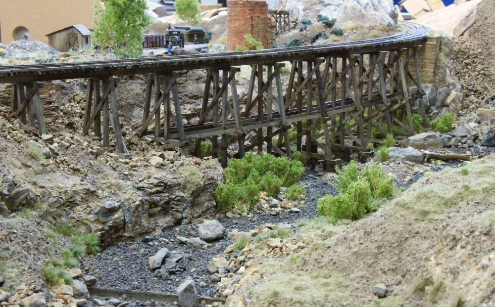 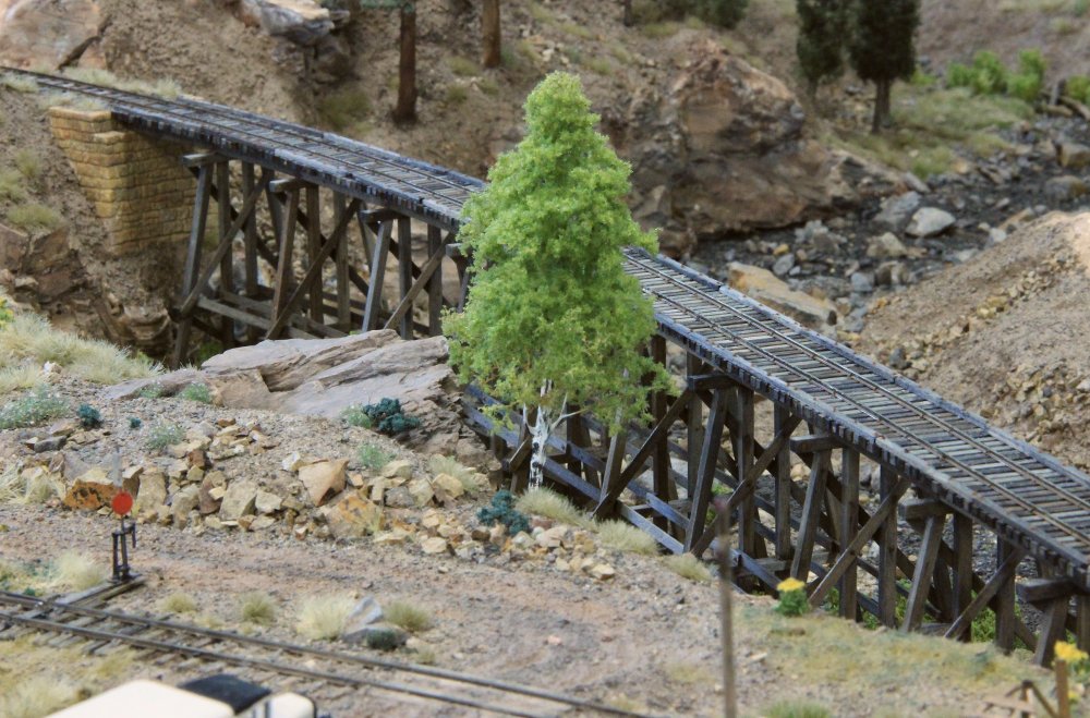 Cheers, Jeff. |
Re: Platte Canon progress report
|
Great work!
Bill Uffelman
|
Re: Platte Canon progress report
|
Looks great Jeff!
Is the tree store bought, or did you build it? |
|
Hi Don,
That one is store-bought, but I know how it's made: SuperTree armature painted white and hand-spotted in dark brown, then flocked with fine-ground foam. Cheers, Jeff. |
Re: Platte Canon progress report
|
Great work, Jeff.
I really like the rock casting next to the green aspen.  And the river willows remind me of Webster. Keep up the good work, look forward to reaching Jefferson! Jim
Jim Courtney
Poulsbo, WA |
«
Return to C&Sng Discussion Forum
|
1 view|%1 views
| Free forum by Nabble | Edit this page |


