Phase I boxcar brakes questions

Previous Topic Next Topic
 
classic Classic list List threaded Threaded
9 messages Options
Reply | Threaded
Open this post in threaded view
|

Phase I boxcar brakes questions

Todd A Ferguson
I purchased 5 of the CW resin kits for the C&S/RGS boxcar when they came out many moons ago.  Last week I took one on vacation with me to build.  Not a difficult kit to build but I ended up with a couple questions regarding the brakes in the later C&S/RGS era.  First the kit and instructions refer to a NY style brake reservoir and cylinder.  This included the parts list and the drawing.  But the included part was the more typical Westinghouse part.  So, the question I end up with is were the cars always equipped with the NY style or were they replaced with a Westinghouse style at some point?  

And if the NY style was used I would assume the brake setup would be as shown in the drawing with the double connected levers between the Queen posts.  So would this setup remain or be changed to the more common setup used with later cars which did use the Westinghouse reservoir and cylinder?  I’m trying to get the models correct but am confused at this point as to what is the correct setup.

Todd
Reply | Threaded
Open this post in threaded view
|

Re: Phase I boxcar brakes questions

Al Pomeroy
Todd,

Westinghouse and NY brake equipment were interchangeable, and basically the same dimensional with each other. how they were rigged may have been different.
my 3d model of type 1 stockcar show below
 

Al P.
Reply | Threaded
Open this post in threaded view
|

Re: Phase I boxcar brakes questions

Todd A Ferguson
That’s a very nice work of modeling there.  I wrote CAD software for GM in the 1980s and was involved in the early Stereo Lithography interfaces to CAD software in the later 80s.  Our Division had two 3D Systems machines in-house.  It was cool then and has come a long long way in 35 years…

Todd
Reply | Threaded
Open this post in threaded view
|

Re: Phase I boxcar brakes questions

Jim Courtney
In reply to this post by Todd A Ferguson
Todd,

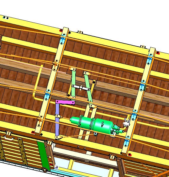
The type 1 boxcars of 1907 used the shorter NY brake cylinder, with the three brake lever arrangement between the needle beams, as in Al's CAD drawing. The longer Westinghouse cylinder was used on the type 2 and type 3 freight cars. With the longer cylinder, all that stuff wouldn't fit between the needle beams--the cylinder piston extended through the "B" needle beam, and two brake levers were used, as on most D&RGW cars post-1924/26.

I think that I recall that you are modeling in On3. If so, Grandt Line, now San Juan Details, has a complete NY brake set in On3:
https://sanjuandetails.com/ny-air-brake-set-type-k-8-x-8-set-contains-misc-pipe-fittings-and-air-hoses-112-clevises-114-brake-chain-c-s-brake-staff-brackets-fittings-brake-wheel-88-retainer-valve-cylinder-release-valve-push-rod-137-brake-levers-ny-brake-cylinder-mounting-brackets/

In Sn3, only the shorter NY brake cylinder is available: https://sanjuandetails.com/c-s-narrow-gauge-ny-brake-set/
You'll have to fabricate the brake levers and such. I use Evergreen HO scale 1x4 for the levers, PBL clevises and 0.012" wire.

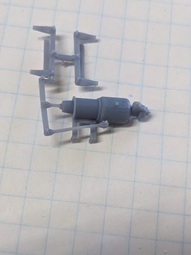
Recently Steve Guty printed me a complete Sn3 part (cylinder/reservoir, brake levers, mounting bracket as a single resin piece. They are beautiful pieces, complete with clevises. I haven't had a chance to use them yet.
Jim Courtney
Poulsbo, WA
Reply | Threaded
Open this post in threaded view
|

Re: Phase I boxcar brakes questions

Todd A Ferguson
Jim,

So if I’m understanding correctly the Phase I cars had the NY brake setup until they’re EOL.  While my C&S interest remains 1905-1915 in On3.  The CW kits are Sn3 and are for my RGS October 1940 interests.

It just seems odd to me that CW would provide the wrong brake reservoir/cylinder in the kit.  I have only checked 2 of my 5 kits but those 2 each had the Westinghouse part not the NY.  Maybe it was just a mistake.  The brake levers and clevises is a resin casting and rather crude.  I was building this car kit at the beach on vacation so I had limited supplies and tools.  I did build up some levers and added PBL clevises.  I’ll post some photos of my effort tomorrow but I want to get this correct before painting and decaling.   Maybe Steve would be willing to print and sell me some of his S scale setups.  

Todd
Reply | Threaded
Open this post in threaded view
|

Re: Phase I boxcar brakes questions

Todd A Ferguson
My underframe construction at the beach…Underframe Phase I
Reply | Threaded
Open this post in threaded view
|

Re: Phase I boxcar brakes questions

drgwcs
Good timing on this- I was (finally) working on my kitbashed E&B stock car and needed to do the brakes. Calling this good timing though is rather amusing- I only started on this thing as a teenager nearly 40 years ago and put it up when the grab irons flew off to be eaten by my parent's puke green shag rug never to be seen again.  
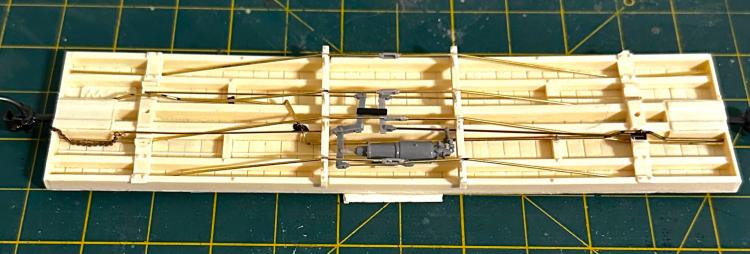
Brakes lettering trucks and couplers are what is left now plus gluing in cattle.  

Jim Curran
Reply | Threaded
Open this post in threaded view
|

Re: Phase I boxcar brakes questions

Al Pomeroy


I found and measured this cylinder casting, which is correct for the C&S cars at the CRRM a few years ago. not clear as to the manufacture. clearly an 8" bore x 7" stroke. this is what is on stock car 7064 at museum.

AL P.
Reply | Threaded
Open this post in threaded view
|

Re: Phase I boxcar brakes questions

SteveG
This post was updated on .
In reply to this post by Todd A Ferguson
Hey Todd,
Be happy to send you some test prints of the brake gear I sent Jim. I'm not set up for commercial operations per se, so just send me a PM with your mailing address, and I'll consider this part of my beta program. :)

This is what it looks like in O scale, where you can actually see the cotter pins--they're more of a suggestion in S and HO.

3D print of NY brake gear in O scale

Steve Guty
Lakeway, TX