Coal chute track?
|
Hi all...
A question. I have an old Slim Gauge News with drawings of C&S coal chutes; I am surprised to see that the ramp portion is drawn as an angle where it intersects the chute portion of the structure. Having had a little experience at 1:1 and vertical curves, I am wondering if this was rendered correctly. The image posted of the Como chutes looks more like I would expect- a vertical curve transitioning rather than a jump from 6% to 1%. The B&B gang would be earning it's keep if it contoured the stringers for the vertical curve. 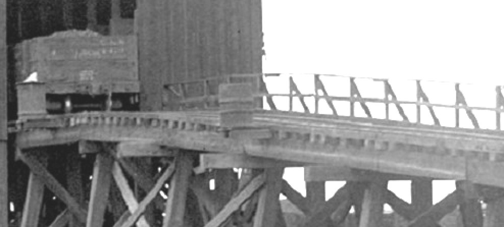 I need to build a coal chute- and I certainly would appreciate some deeper insight! Thanks! Stan |
|
Administrator
|
Hi Stan,
The drawing you have from the old Slim Gauge News was done by Joe Crea, and if memory serves me right, it's of the one at Pine Grove. The picture you posted is of the one at Como, which was quite different in that it has a shed over the bins, but more germane to your question, had, I believe a mush shorter and steeper ramp. I'm including a pic of the transition of the Dickey Coal chutes, which had a longer and less severe grade, more typical of what you might find at Pine Grove or one of the others. This was built for my original Dickey Yard on my layout in Boulder back in the 80's. The Dickey structure was the largest, 12 chutes, 6 per side. This model was built by Todd Hackett, who researched the Dickey chutes independently from what Joe had done, but they did collaborate and commiserate on the Dickey project which turned out extremely well. Use the search function on this page and it will link you to a wildly informative and meandering thread on these interesting structures. A bit of advice, start building some coal cars! If you have a coal dock like this, you'll need at least 6-8 coal cars around. Some loaded, some not. Mike |
|
In reply to this post by snapped_bolt
Must have been a transition, why would there be an angle?
|
|
In reply to this post by Mike Trent
Hey Mike,
I just know that you can't lay rail at an angle (vertical) and expect it to last. One nick and the rail breaks! As far as equipment- no chance of "high centering" or "bottoming out", but the stress on the draft gear would be terrific. On new draft gear, that is. I suppose if you have sufficiently worn draft gear you could move the cars OK. In the picture I posted you can see that there is not only a "gentle" vertical curve of the rails, but there is an arc formed by the ties. Now that brings a few possibilities: 1. The image is bent. Just there. 2. The stringers were either adzed in place presenting a gradual transition 3. The rail traffic gradually conformed the track to it's liking. I personally prefer #2. This would involve assembling the stringers then sanding them to a curved template. Coal cars? I have 8 underway. Collecting parts as I can find 'em. Still struggling with the "where to add the weight" issue. I plan on doing the full brake and air system, so my choices of weight placement becomes limited! Cheers!!! Stan |
|
Stan,
If you had a solid base to fix the bents to the stringers should bend- maybe dampen with water- steam,or cut the underside with sawcuts(fine slots) they should bend easy then. Paul R. |
|
I've seen some pretty sharp vertical kinks it rail (including some of the rails we used at Como). Once the kink is set, I don't think it would snap due do a nick. If there was a vertical curve, it wasn't very long. The kink or sharp vertical curve could be handled with a rail joint with joiner bars fabricated with an angle or by heating the rail as it was bent. I don't think this short vertical curve (even if a sharp angle) would impact draft gear. The angle between a 6% grade and level grade is only about 3-1/2 degrees, and the couplers should have enough clearance to allow that angle. If there was a bit of a transition, it could have been handled by notching a few ties on each side of the bent (with an adze or hammer and chisel), or by having a few thicknesses of ties.
As has been stated already, Como appears in some photos to have a transition:  But if you lay a straight edge along the approach trestle and deck track in this photo, there doesn't seem to be any tranistion:  Pine looks to have a straight ramp, with very little room for a vertical curve: 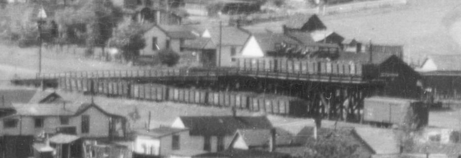 The actual transition isn't visible in this photo, but it doesn't appear that there could have been much of a vertical curve: 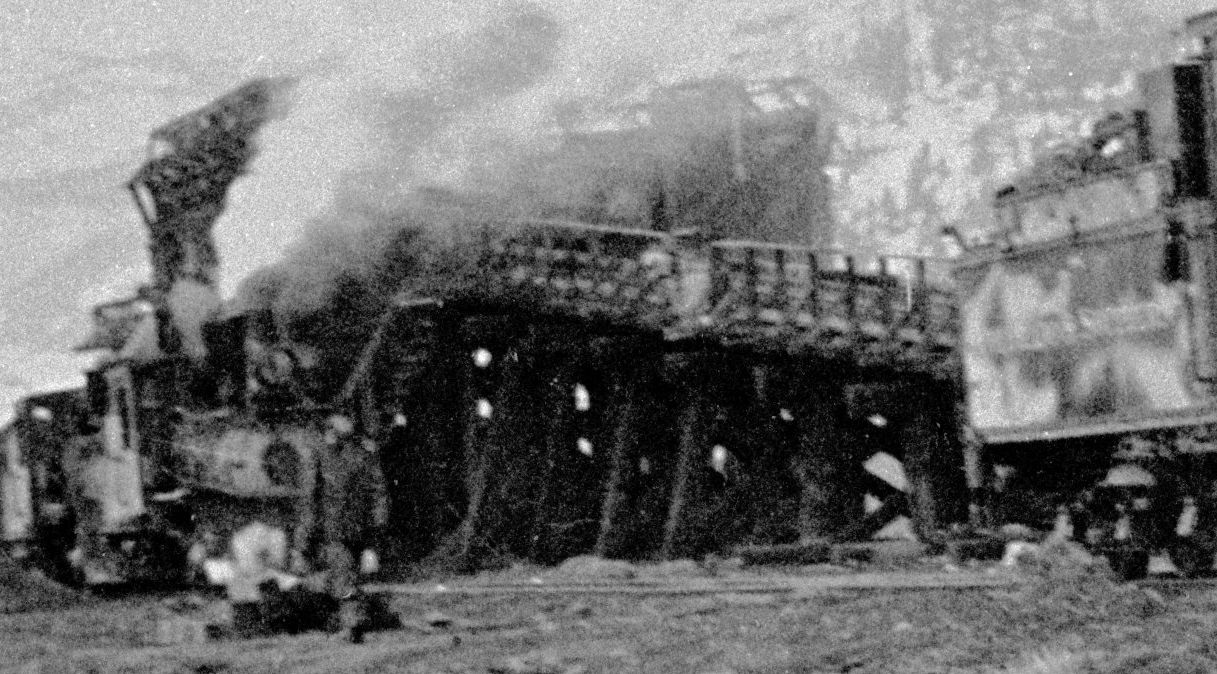 Joe Crea used C&S drawings that Elwood Bell had obtained for Pitkin for his drawing . He also used photos of Pine's trestle, so it was really intended to be representative of a typical C&S coal trestles rather than an accurate drawing of any one trestle (which I'm fairly sure he acknowledged when the drawing was published). I have a copy of the drawings that Elwood let me make (although they are in Colorado and I'm not at the moment), and they show a typical pocket and the pilings used instead of bents at Pitkin (while Joe drew trestle bents as were used at the other trestles). I'm fairly sure they didn't show a profile of the track to show how the transition was handled. |
|
A different railroad, granted, but there doesn't appear to be a vertical curve at Sargent:
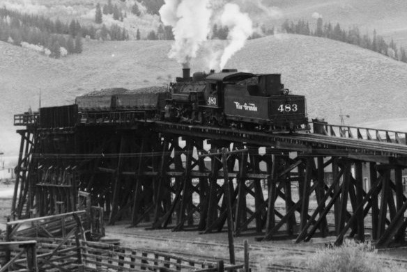 Incidentally, the D&RGW used a 1% grade across the top (presumably so they could move the coal cars for unloading without a locomotive). Did the C&S also follow this practice? |
|
Yes, Jeff,
The C&S coal chutes had a very mild grade at the top of the ramp, adjacent to the coal bins, to allow coal cars to be moved by gravity and hand brakes.
Jim Courtney
Poulsbo, WA |
|
I used Joe's plans in Slim Gauge News to build an HOn3 version when I was in high school. I recall the bins were quite complex to build. The whole works was over three feet long. Wish I would have known Todd and Mike back then! And I doubt there are any pictures to share.
I have a Crystal River kit and someday Breckenridge will finally get a proper coaling facility. But I never got the trestle, so will have to scratch build that.
Keith Hayes
Leadville in Sn3 |
|
In reply to this post by Jeff Young
Another different railroad, to show what grade transition cars could handle.
The WP&Y coal bunker at Skagway has a 20% grade, with a transition at the top covering about 3 feet. Cars were pulled up by cable. http://wpyphotos.com/skagway/SKcoal/WPYShops.bunkerRyACMorsea.jpg http://wpyphotos.com/skagway/SKcoal/coalbunkerside1_5114.JPG http://wpyphotos.com/skagway/SKcoal/SKcoalBunkerPlanPieces/images/DSCN0288.JPG Bruce Pryor |
|
In reply to this post by snapped_bolt
According to the Railway Gazette of Feb., 1892: 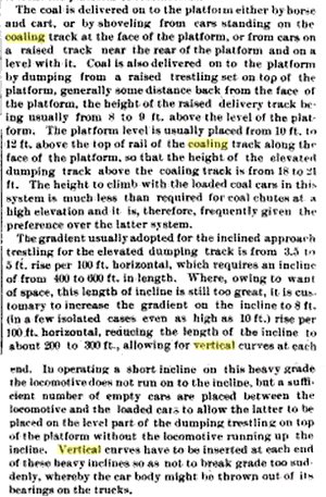 The most sensible way to put a vertical curve into the stringers could be done several ways, i.e., on-site, or at a mill. The stringers weren't bent to accomplish this. I suppose the ties could have been adzed as well to accomplish this. Jeff- the Sargents coaling dock appears to have a vertical curve in it. If the image is modified, you can make it out. Since there is no need for attaching the walkways with a corresponding vertical curve, they can be installed "straight". The highlighted photo shows the tender, locomotive and gondola running gear in a gentle arc. Just use a straight edge against the cars and loco- not structure. 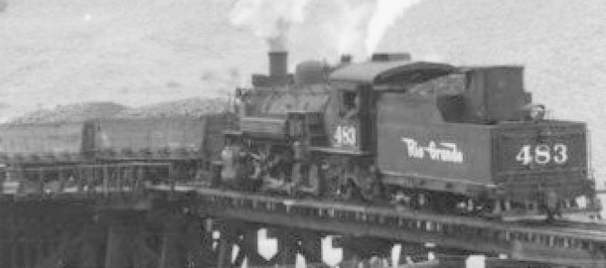 The tail track has a very small angle, and this could be accomplished by a few shims. Lay the ties on the stringers, and spike, with 6 to 12 ties shimmed to provide a vertical curve. There would be no need to traverse this part of the dock with a locomotive other than for a "thrill". The original picture shows the bottom of the stringers showing chords-just straight lines between the caps. No "bend". The stringers are also cut to the length to span between two caps, there are no longer sections. The bottom of the stringer runs straight between each one, and the rail above it has a vertical curve. The bents are also graduated to a curve, as can be seen in the original image. The bottoms of those stringers are chords that correspond the the curve in the rails. So many of the pictures are taken from an adjacent county- and you really would need to be in position, and close, to capture the vertical curve. The drawing I refer to shows a transition of only a few degrees. In laying rail, you just don't want vertical angles bent into it. Rails have always tended to have transverse fractures leasing to some form of a vertical break. Rails indeed are notched and then broken to make quick cuts- such as for loading scrap welded rail. A preloaded condition caused by a vertical bend would break when struck; (such as the blow from a spike maul). If not then, it wouldn't be very long before loaded cars, or locomotives, or just extreme cold causing contraction and a pull-apart. Anglebars are heat-treated; I just have a little trouble believing that a common track gang could de-temper the anglebar, bend it vertically to the proper angle, then re-temper it for such a use. Anglebars can be heated, but not so much that the temper is lost. If lost, it is soft, and will deform easily with ambient heating or cooling, or just straighten out as the wheels roll over it. Perhaps a logging road or such might try something such as this, but nearly all logging installations were not for the long-term. They weren't expected to last. I have yet to see any drawings that were actually part of the Standard Plans. All I have seen are drawings, but there are no notations for neither nor approval by any department. A legitimate drawing that would be "quoteworthy" would have these notations. Without them, there is no actual proof that a standard was ever established based on the drawing cited. Unfortunately, the "approved" (by actual railroad management) drawings that are available are few. If modeling, we are stuck with what we can find. There are many reasons drawings may be lost forever, including fire, intentional disposal, theft by collectors, floods....you name it. An "approved" drawing of a coaling dock would have a notation for the detail for the transitions. It certainly wouldn't omit the detail, essentially leaving the decision up to the B&B gang to do whatever they felt like doing. A Standard Plan leaves no guesswork. To sum this up personally- I will be installing 3 vertical curves- at the bottom of the ramp, at the chutes, and the tail. Hopefully this will generate some conversation. For ramps that have been built and function, this isn't an issue. Cheers! Stan |
|
For what it’s worth, the Sargent plan doesn’t include any mention of a vertical curve:
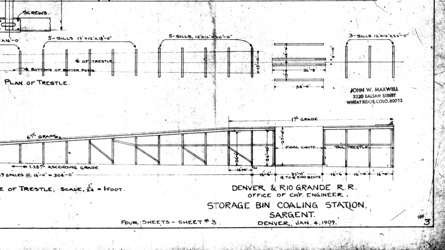 |
|
In reply to this post by bcp
This is an amazing structure! But there is indeed a vertical curve shown in the drawing detail. In this case, I would think that if for no other reason, it would be there to avoid getting the car hung up! Thanks for posting these! I sure wouldn't want to see even ONE free-rolling car leave the building.... Thanks! Stan |
|
In reply to this post by Jeff Young
Jeff.... This is Sheet 3. There are three other sheets for this plan. Do you have access to them? This is only PART of Sheet #3. This part looks more like a "General Arrangement" or "Overview". Cheers Stan |
|
In reply to this post by bcp
I should add that the images DO NOT show the vertical curve well. But when zoomed and the image lightened, you can make out that short stretch of the vertical curve. The actual blueprint SHOWS the installation of the vertical curve. Just thinking.... Stan |
|
Hi Stan,
Send me your email address at jeff( at )rokeby( dot )ie and I'll forward you a copy of all sheets. Cheers, Jeff. |
|
In reply to this post by Jeff Young
I had forgotten all about the folio drawing for the coal trestle at Como. It does show a vertical curve in the span two before the bins (it looks like the stringers are actually bent, which doesn't seem to be feasible for such large timbers). Keep in mind that these folio drawings were not always accurate. I would trust most information written on them (dimensions, capacities, etc.), but the actual drawing portion often doesn't match the actual equipment very well.
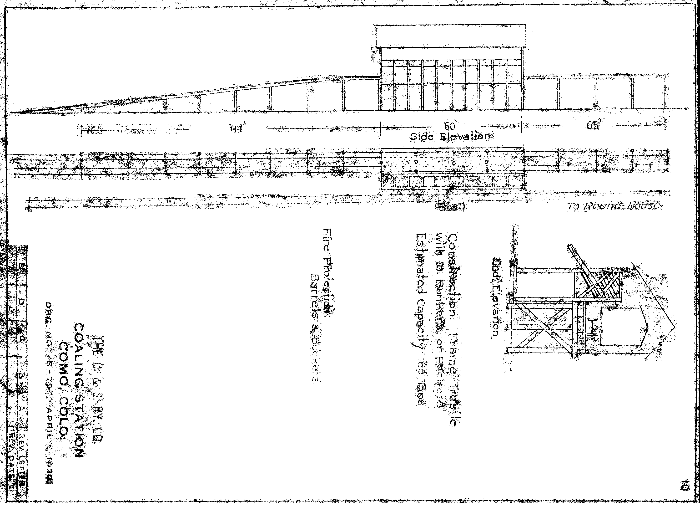 I added some straight lines below the stringers for reference: 
|
|
Thanks Todd!!! Later, Stan |
«
Return to C&Sng Discussion Forum
|
1 view|%1 views
| Free forum by Nabble | Edit this page |

