Building Sn3 Three-Way Stub Switches with Fast Tracks Fixtures
Building Sn3 Three-Way Stub Switches with Fast Tracks Fixtures
|
This post was updated on .
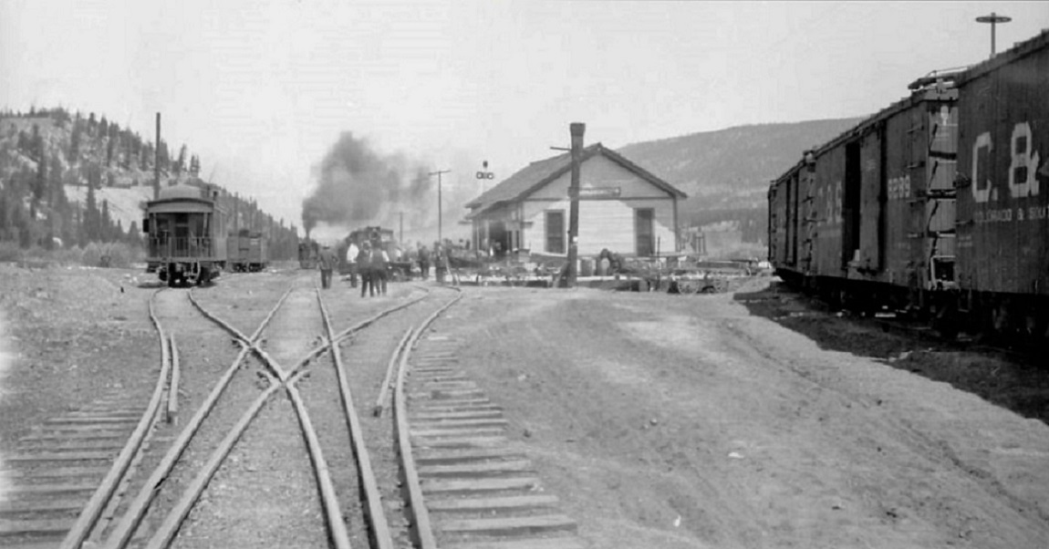 The stub switch discussion on the "New C&S . . . Offerings" thread seemed to be going in new directions, thought it should have a thread of it's own. Since Fast Tracks won't build a 3-way stub fixture for us Sn3 folks, I wondered if I could adapt a standard Fast Tracks fixture to that end. I have made a couple of number 6 standard stub switches and it occurred to me that a 3-way stub is a right and left standard stub joined together in the middle. I'm sure I want number 7 three-ways for my Breckenridge project, but new fixtures from Fast Tracks have a 2-3 week build time plus shipping from Canada takes another week. I decided to experiment this weekend with my number 6, code 55 fixture. But Todd's last post got me thinking about an expanded experiment: The only thing I don’t like about PC ties is trying to make them look like weathered wood. I sometimes use an Atlas Snap Saw to scribe some simulated grain into the copper foil. For fun I sat down and made a number 9 stub yesterday using my template. I realized I scribed a line on the template crossing the rails where the rails were properly spaced for the head tie. I didn’t have any PC ties cut so I just soldered a few pieces of rail across the tops of the rails. This is similar to how Railway Engineering does his. That way they can just be spiked or glued to the wood ties and there is no trying to match weathered ties. Once in place the top rails are just removed and any solder wicked away. Easy. Took me about 45 minutes to make the switch. Proto87Stores.com sells both cast and milled frogs too in a variety of sizes... I love their etched spikes. Best spikes I have ever used... Perhaps I could build the stub switch, then install it on weathered wood ties, spiking it with those Proto-87 spikes (spikes now on order). And I've been meaning to try a new roadbed material, a homasote substitute, now that milled Homabed is no longer available. First the stub switch. I'm going to try to use the PCB ties as construction aids, like soldering short pieces of rail to the completed switch for installation, as in Todd's post--only upside down. So I didn't bother gaping the copper foil or distressing the ties, and I cut them so they stopped just short of the center line of the straight route on both the R & L fixtures. Then it was a simple matter of of building the diverging half of both switches on the same fixture: 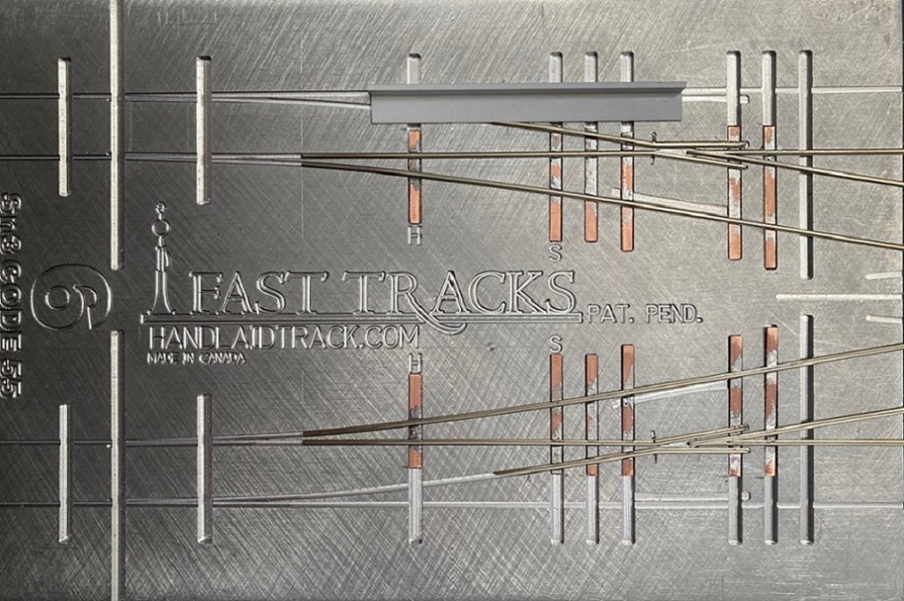 To pull off this conjoining of the two halves, the points of the center frog (the "crotch frog" as Todd calls it) had to be left in two halves, but aligning perfectly. The center frog points are formed from a continuous length of rail that runs from the frog point and ends as the inner wing rail for the R and L diverging route frogs. The distance between the rail grooves in the fixture is 0.540". I was able to make a simple jig from Evergreen styrene to make things line up: A piece of 0.060" x 0.250" styrene fits snugly into the code 55 rail groves on edge. I laminated a length of 0.020" x 0.030" styrene to a piece of 0.030" x 0.250" to make a 0.27" wide centerline jig, attaching it to the upright piece with MEK. The jig is positional on either side; a piece of rail is filed to a number 4 frog angle on one end, then slid down the groove and abuts the edge of the jig. The bend for the wing rail is then marked, notched and bent, and the wing rail then cut to length to fit in the fixture. After beveling and adding a bit of chamfer to the inside of the wing rail end, it is positioned into the fixture and soldered in place. 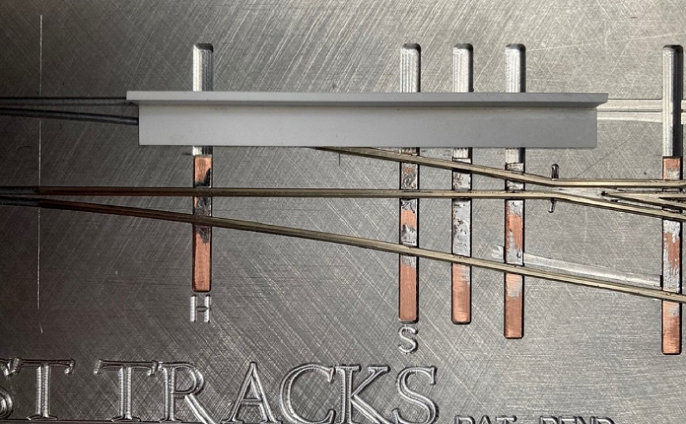 With the two halves completed and removed from the fixture, they look like a zipper that needs zipping: 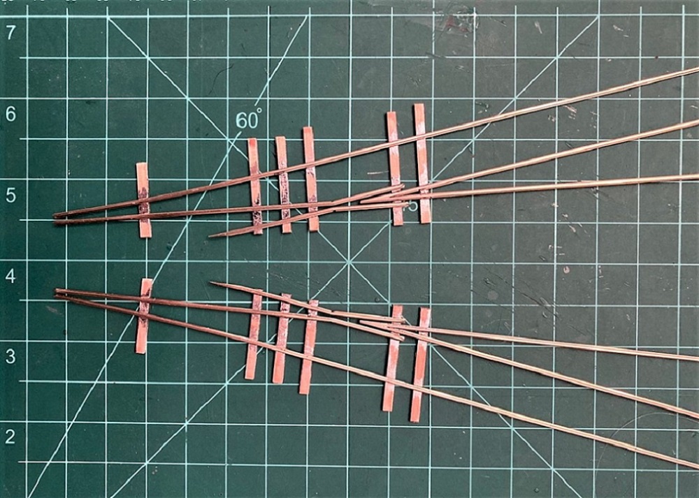 To zip up my crotch frog (ouch!), I held everything in alignment with multiple track gauges. I soldered the center frog points together first, then added three full length PCB ties, one under the center frog points and one spanning all rails of the diverging routes past the frogs. I filed a gap and textured the single tie on the left. It is the only PCB tie that will remain on the final switch after installation, the first tie beyond the head tie, to keep all six rails in alignment. 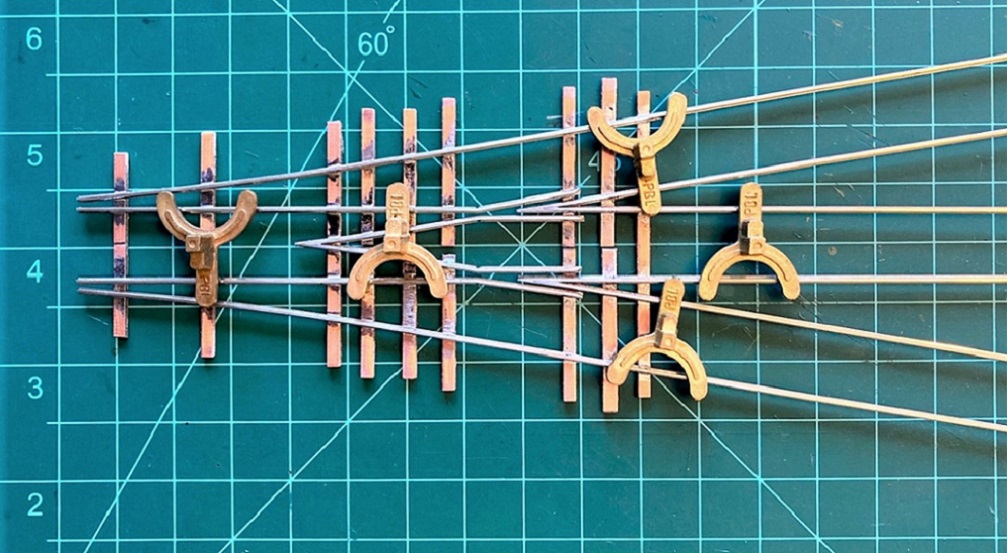 After everything was soldered together and the two made one, I turned the switch upside down and fluxed and added solder to the bottom of the 3 frog points to make them sturdy. Only two pieces of rail had to be installed outside the fixture, the rails forming the wing rails of the center frog and the inner most diverging rails at the head tie. After cleaning up all the excess solder, and washing thoroughly with Dawn in hot water (to remove residual flux), this is how it now looks: 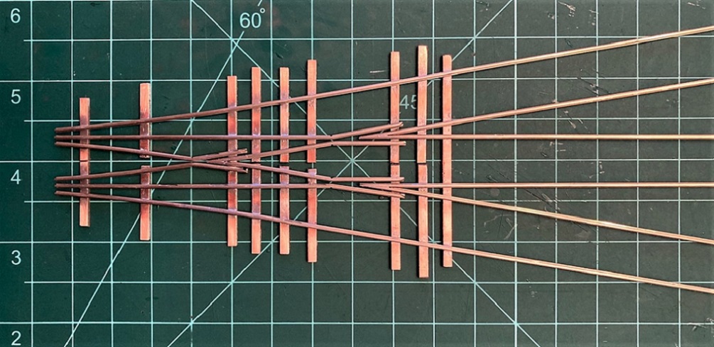 Perhaps Todd is correct and it would be simpler just to assemble the switch parts directly in-situ. But the twenty or so switches that I've built in the Fast Tracks fixtures are bullet proof, they all operate flawlessly. It may be a crutch, but it is my crutch. Next time: Head ties, chairs, switch ties and a trial of new road bed . . .
Jim Courtney
Poulsbo, WA |
Re: Building Sn3 Three-Way Stub Switches with Fast Tracks Fixtures
|
Brilliant, Jim. Way to think outside of the box!
|
Re: Building Sn3 Three-Way Stub Switches with Fast Tracks Fixtures
|
This post was updated on .
In reply to this post by Jim Courtney
Jim,
In some bored downtime I did a couple of stub related things. First I checked Lee’s diagrams in the Files area and the templates for the 2 sizes of 3 way stubs I mentioned are there for the printing along with a few other stub diagrams. He also included the wiring diagram that he used for his and the self centering design for switch machine and power routing too. I have seen his operate and his system works well with common parts. Our friend from Buena Vista also had a 3 way switch machine... I also made several more stubs with my number 9 template. Again not being a fan of trying to make copper foil look like weathered wood I tried another idea. I decide to try a substitute for the pc ties that would allow easier and less cleanup in building than soldering cross pieces to the top of the rails. Again my goal would be to avoid pc ties and enable easy spiking to wood ties. I have a supply og code 70, code 55 and code 40 rail on hand. I determined that the code 55 tail can be substituted for the pc ties buy just cutting a piece that will span the rails in the jig in place of the pc ties. The running rails are all then just soldered to the upside down code 55 rail. I used a piece under each end of the frog and one back toward the head tie location. This worked well and would make spiking into location easy. Then the rails across could be removed from underneath fairly easily by unsoldering. And there is really no solder to clean up. I also apply some solder on the bottom of the frog where the point and closure rails all come together. This adds strength and makes the frog electrically connected together. If you would like me to send you a photo I will email you one as I’m not sure how to post photos here. Todd. |
Re: Building Sn3 Three-Way Stub Switches with Fast Tracks Fixtures
|
This post was updated on .
Todd,
We are both thinking along similar lines. I used the PC ties primarily to make the switch sturdy when removed from the fixture, so that I could cut gaps to electrically isolate the frogs (probably my next post) with a jewelers saw. I will remove 2-3 of the PC ties before trying to spike down the rail to the wood ties. Since the PC ties are about 0.055" thick and standard 5 x 7 wood ties are about 0.075" thick, it is my sincere hope that after the switch is spiked to the wood ties in the current tie gaps and is secure, that I can unsolder the PC ties, slide them out from under the rail and then slide new stained wood ties in, to take their place. We will see if that works. I hope to end up with a single PC tie (first beyond the head tie) to keep all six rails on the head tie firmly aligned. Like you, I don't like the appearance of the PC ties, with all the gaps and a surface that I can never get to match stained ties. I like your idea of upside down rail in lieu of the PC ties. I also have some very skinny/thin N scale PC board ties that might also work. Please post some photos of your track work so we can all see them. Simply use the "insert image" tab above the text field when posting: When the screen opens, click "choose file", browse your photos in your computer or phone, click on the image you want, then click "insert image". Choose float "none" and resize "none" as the posting options. Images with a horizontal width of about 1000-1100 pixels work best. Also see Darel's sticky post: http://c-sng-discussion-forum.41377.n7.nabble.com/Sticky-How-To-Image-Upload-td171.html
Jim Courtney
Poulsbo, WA |
«
Return to C&Sng Discussion Forum
|
1 view|%1 views
| Free forum by Nabble | Edit this page |

