Brake staff /cylinder confusion and mismatched trucks!!
12


12
Re: Brake staff /cylinder confusion -- 1900 C&S stock car at museum.
|
This post was updated on .
John,
As to the handbrake though, now I'm even more confused. If indeed the cylinder rod cannot move unless the air is activated, then how can the handbrake work in the modern rig, when it is attached to the essentially fixed lever end that is enforced by the non-moving cylinder? As Chris pointed out: "The brake piston rod is floating without air, remember that the air moves the piston, the cylinder return spring pulls it back as the air is released. The piston rod has to move during the application of the handbrake." Further, it depends on the situation in which the hand brake is applied. In my limited career as a brakeman there were two such situations: 1) Switching or spotting a car (or string of cars) in which all air in the reservoir and cylinder had been bled out. Applying the hand brake would pull the piston out of the cylinder, the only resistance being the internal spring attached to the piston rod. As the piston is externally pulled to its maximal extent, the levers apply the brakes via the levers, rods and brake shoes. 2) Setting out a car or cars with fully charged reservoirs: When uncoupled (unless the angle cock to the set-out is also turned), as the air hoses separate, the train line pressure in the car falls to zero and the triple valve diverts air under pressure (120 psi?) from the reservoir into the cylinder, pushing the piston to its full extent, applying air brakes. As a safety precaution, the brakeman sets the hand brake as well, so if the air gradually bleeds off (or some nosy kid pulls on the bleed rod to see what happens), the car doesn't start rolling. With the A brake wheel arrangement, the same forces work on a car without air, as the piston is fully retracted and becomes a fixed tether along with the dead rod on the side of the cylinder. The only problem I see with the A end arrangement is in the second situation: If the car is set out and air brakes are applied at uncoupling, there is a new fixed point toward the B end of the car (as the piston is now fully extended). If the hand brake is tightened as a safety precaution, what happens if the air in the cylinder is slowly or purposely bled off? Seems there would be slack that would develop in the brake rod and lever system and the car might start to roll. Often brakemen or switchmen will wedge a piece of 2x4 or such under one wheel as a chock, to further prevent the car from errant rolling. And, as you pointed out, part "Y" in the Grandt diagram did exist (actually two of them). They were strap metal brackets, mounted to the center sills. The center rail, that supported the hanging bracket between the two levers, was in turn bolted to them (see the B&W coal car photo above). The stock car at the Museum, in Keith's color photo, had a variation--instead of two straps to support the center rail, a wide block of wood was bolted to the two center sills, and the center rail (shaped like a grab iron) was bolted to the wood block, like a grab iron bolted to the side of a car. Anyways, this is the only way I can make sense of this stuff.  May I suggest that the stop could have been as simple as a second piece of chain, attached to the end of the brake rod where the chain to the brake staff is attached, but leading to a fixed point, perhaps on the bolster or the frame end beam. I really like that idea, a simple but elegant solution to the "stop" problem! 
Jim Courtney
Poulsbo, WA |
Re: Brake staff /cylinder confusion -- 1900 C&S stock car at museum.
I would strongly caution against imagineering an unfounded solution in favour of omitting the unknown rather than providing a non-prototype solution. John, I fully understand your angst, I had the same in '94 building my Ph1 Coal car. Just how different was the brake arrangement from the Ph1 or is that also an unknown?
UpSideDownC
in New Zealand |
Re: Brake staff /cylinder confusion -- 1900 C&S stock car at museum.
|
Point taken, Chris.
I'll keep searching for the Holy Grail.
Jim Courtney
Poulsbo, WA |
Re: Brake staff /cylinder confusion -- 1900 C&S stock car at museum.
|
This post was updated on .
Thanks, Chris and Jim!
Chris, your post explaining the cylinder motion apparently came in while I was writing mine. I didn't see yours until now- thanks for clearing this up. Jim, your description of how the handbrake is actually used is very helpful. Your description of the problem scenario with the A-end rig makes a very good point. That would be a real drawback- maybe that's why that arrangement was later abandoned. In fact, in light of this, the later rig looks like it might have originated as a quick fix to the old one, just chopping off the rod to the A end handbrake and bolting it to the needle beam, and attaching the new B end handbrake rod next to the air cylinder attachment point. Yes, my suggestion about the second chain was just for fun, certainly better to leave this part a blank until (if ever) the necessary information surfaces. John John Greenly Lansing, NY
John Greenly
Lansing, NY |
Re: Brake staff /cylinder confusion -- Hand brake failures
|
Yes, John, I've wondered as well whether the A end brake staff arrangement was prone to failures when backing up the air brake application. This might have been the impetus to move the hand brake to the B end of the car. There are quite a few anecdotal stories of set-out cars mysteriously breaking loose and running away, prior to 1900.
My favorite is the Charlie Squires tale of six loaded ore cars, "tied up at Breckenridge", somehow breaking loose and finding their way to the mainline. The six cars ran down the Blue River valley until they reached the Leadville switch at Dickey, where they derailed and demolished the south end of the Dickey depot. Squires reportedly ran in a new telegraph line, after the carpenters had repaired the depot.
Jim Courtney
Poulsbo, WA |
Re: Brake staff /cylinder confusion -- Hand brake failures
|
Guys,
Glad to see this thread alive again and some thought going into it. I've nothing to add so I'll sit back and watch. Thanks! Doug
Doug Heitkamp
Centennial, CO |
Re: Brake staff /cylinder confusion -- 1900 C&S stock car at museum.
|
In reply to this post by John Greenly
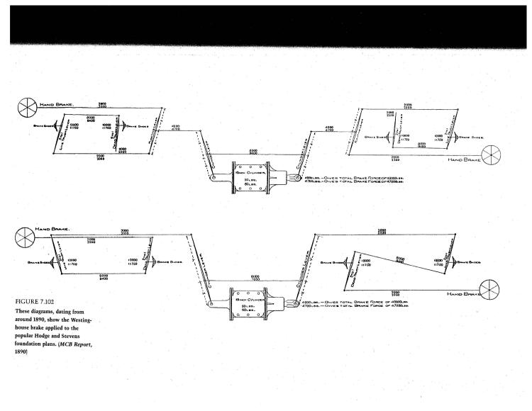
The following foundation brake rigging is from "The American Railroad Freight Car". Hand brake can be on A and/or B-end. Very interesting book for those who don't have it in their library.

|
|
In reply to this post by Jim Courtney
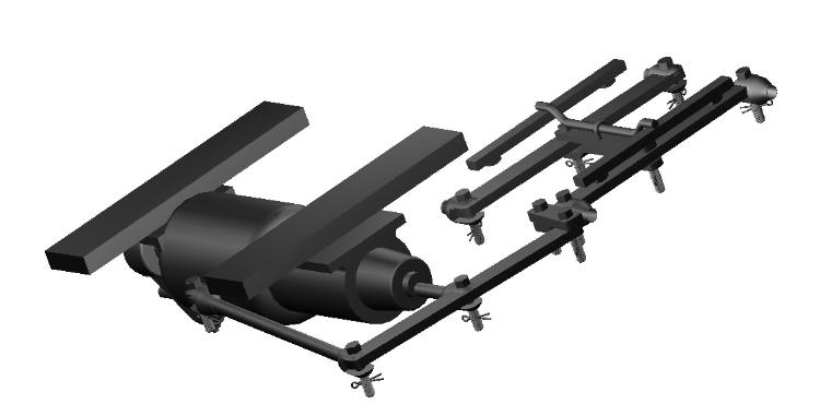
In looking back over this thread to figure out how to 3D print the brake gear for some 1902 cars, I think I've been able to capture most of the detail in the photo Jim posted. I left out the long rods, which would be better handled via wire (.015 in HO, and similarly, if larger, in other scales).
Here's what the 3D model looks like:  Modeling the cotter pins is probably gilding the lily, but only took a couple minutes. :) If anyone spots anything fundamentally wrong with this, let me know. Regards, Steve Guty Lakeway, TX |
Re: Brake staff /cylinder confusion and mismatched trucks!!
|
Wow, Steve, WOW!
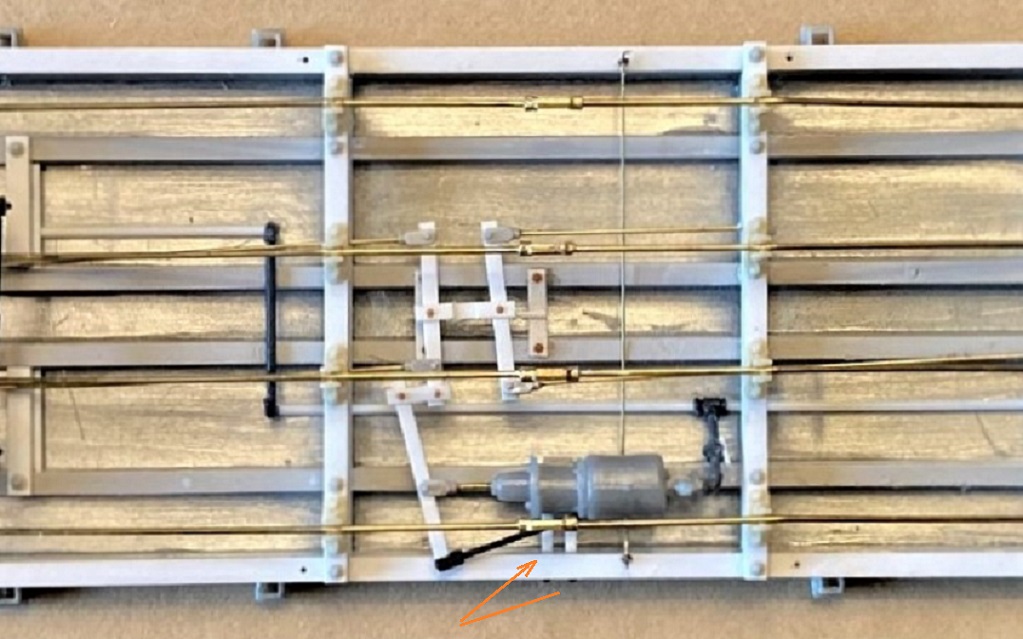
That's a beautiful piece of CAD work! The only quibble that I would have is the brake cylinder mounts. Unlike the D&RGW, the small "New York" brake cylinders, used on the freight cars from 1898 to 1907, didn't have a rear mount, at the rear of the reservoir. And the brackets that attached the cylinder to the sills are shown, in both Poole's and Stear's plans, as two pieces of strap metal, each about 2" wide, about 3/4" thick. They ran from the inside edge of the intermediate sill (bolted to the bottom of the sill) to the inside of the side sill, where they bent down (or up from the rail) at 90 degrees and were bolted to the inside of the side sill. The latter attachment resulted in a pair of visible bolt heads on the outside of the side sills. Here is my rendition of the brake gear on the underframe of a St. Charles coal car, under construction:  I've come up with a system using styrene strips, PBL clevises, Tichy rivets and 0.012 wire to build up the brake levers and rods, and use the Grandt small "NY" cylinder. Your potential print looks to be much more refined. I don't know how well the cotter pins are going to render in HO scale, but (ahem) they might print well in S scale. 
Jim Courtney
Poulsbo, WA |
|
In reply to this post by SteveG
Thanks, Jim, great feedback as always. I'm pretty sure I had used an earlier model of the Westinghouse brake cylinder from an old Gazette article dating back to 1978, which is where I got the mistaken idea of the two supports' placement.
I do note that the Poole 1902 diagrams spec a Westinghouse 8x8, but I've not been able to locate a good diagram of the NY equivalent, although I suspect that form follows function pretty closely here. I also, in looking for a possible NY diagram, discovered the previously unknown-to-me fact that NY Air Brake started by buying out the assets of the Eames vacuum brake company, and that NY Air Brake is still in business today--I had thought Westinghouse pretty much owned the market. I'm heading up to the Denton area for the holiday, but will do some updating on the diagram when I get back. And given the small footprint of the lever and cylinder assembly, doing a test print in multiple scales should be easy, much like the tender shells and bolsters. If it turns out at all reasonable, I'll send you a sample for further critiquing. Regards, Steve |
|
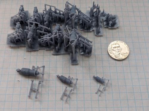
As it turns out, the hardest part of 3D printing these is getting them off the supports:
 But this is what these look like in O, S, and HO respectively. (The cotter pins are only really visible in O.) I'll see if I can tweak the default-generated supports to increase the successful yield rate. Steve Guty Lakeway, TX |
«
Return to C&Sng Discussion Forum
|
1 view|%1 views
| Free forum by Nabble | Edit this page |

