Brake staff /cylinder confusion and mismatched trucks!!
12


12
Brake staff /cylinder confusion and mismatched trucks!!
|
This post was updated on .
I was studying this DPL photo of Pine in the late 1890s under maximum magnification earlier today:
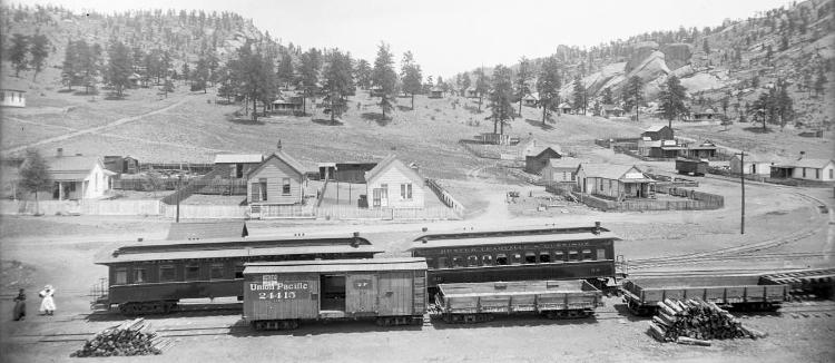 http://cdm16079.contentdm.oclc.org/cdm/singleitem/collection/p15330coll21/id/3681/rec/5 The 3 freight cars all carry UP numbers for the DL&G. The boxcar 24415 is numbered in the 24276-24470 series, listed as a 27 foot, 14 ton car, built by the UP in 1882-3. It is my most recent understanding that brake cylinders always point toward the brake staff end of DSP&P/DL&G/C&S freight cars, but this confuses me all over again: 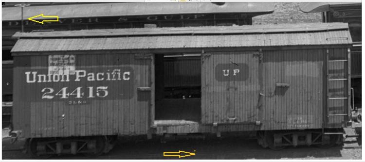 The brake cylinder points to the right end of the car, the bracing rod from the reservoir to the main brake lever (like on all C&S "phase 1" cars), is clearly visible, as is the connecting pipe from triple valve to the main train line. Yet, the brake staff is on the left end of the car! Please, someone, tell me how this worked! The boxcar has all the features of a 27' UP built boxcar, including the cast corner irons with the rectangular poling pocket on the side of the corner and no visible truss rods (they're up next to the center sill), but the trucks are not the familiar "type B" UP swing beam trucks that Ron Rudnick describes. Instead, they look like the 14 ton trucks used on the 27' coal cars. BTW, is that a designated "Grain and Hay" placard over the "Union Pacific" lettering? It looks painted on, not a paper sign. The two coal cars also have a lot of disturbing surprises as well. First off, DL&G numbers 3252 and 3210 are of the series 3037-3221, which were listed as 12 ton, 26 foot Litchfield flat cars: 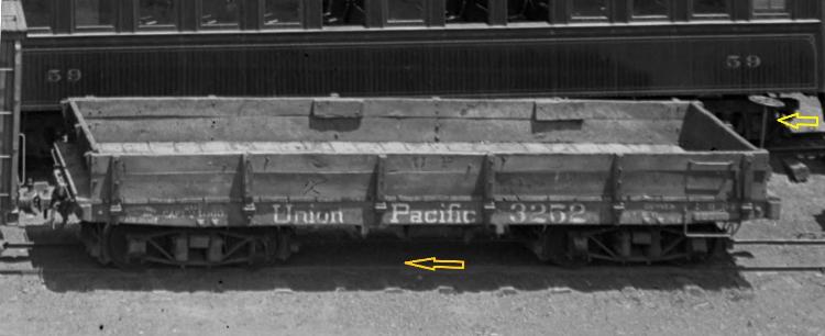 So these are flat rebuilds into low side, 2 board coal cars. The Litchfield builders mark is visible on the left end of the tapered side sill. But the car doesn't have the typical 8 stake pocket arrangement and the Litchfield plate bolster isn't visible under the sill, instead there are paired odd square bolts in the side of the sill. And the brake cylinder is odd: Again it seems to point to the left while the brake staff is on the right end of the car. Odder still, there is no cylinder! It's just a long reservoir with triple valve on the right. Is this some sort of split reservoir/cylinder arrangement? If so, why? And why such a large reservoir, it looks to be as large as a passenger car reservoir. Finally the trucks under this Litchfield "flat"--they look nothing like any South Park or Central truck I've ever seen. Does anyone know what these are?? 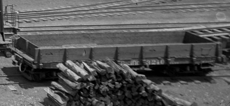 Litchfield "flat" 3210 looks much more what you'd expect: Eight stake pockets, plate bolsters under the sill, and 12 ton Litchfield trucks. I'm in the process of building some Sn3 Cimarron Works kits for the 27' boxcar, and plan to paint and letter them like these two beauties, albeit with automatic couplers, weathered as they might appear in 1909 : 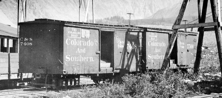 But now I don't know how to complete the underframe. Look at C&S 7408: The brake staff is at the far (right) end of the car, yet no brake cylinder/reservoir is visible between the needle beams--it must be on the other side of the car, pointed to the left, away from the brake staff. And those don't look like UP "type-B" trucks on further study. The tall transoms look a lot like the coal car type trucks, as on DL&G 24415 above. So now I'm stuck and don't understand the brake arrangement on the inherited cars. Please, someone 'splain it to me!
Jim Courtney
Poulsbo, WA |
Re: Brake staff /cylinder confusion and mismatched trucks!!
|
According to the December 1893 ORER 3252 belongs to the SOUTH PARK AND LEADVILLE SHORT LINE part of series 3250-3252. The note below the listing says "The equipment of this line is marked "Denver, Leadville & Gunnison" and cars are fitted with property plates showing their ownership to be "South Park & Leadville Short Line".
This probably doesn't explain the brake cylinder but it might explain the stake pockets. Ken Martin |
Re: Brake staff /cylinder confusion and mismatched trucks!!
|
This post was updated on .
Thanks for that bit of info, Ken! That's why I love this site, I always learn something new every day.
That would explain a lot of odd things, the trucks (which look like modified, now sprung UP "type B" swing beam trucks), the lack of visible Litchfield bolster plates under the sills, the odd square bolt heads on the side sill (securing a bolster of unknown type) and the reservoir only without cylinder, possibly a split reservoir/cylinder. Do you think the little rectangle at the right end of the side sill, over the stirrup step, is the property plate for the "SP&LSL" owner?? 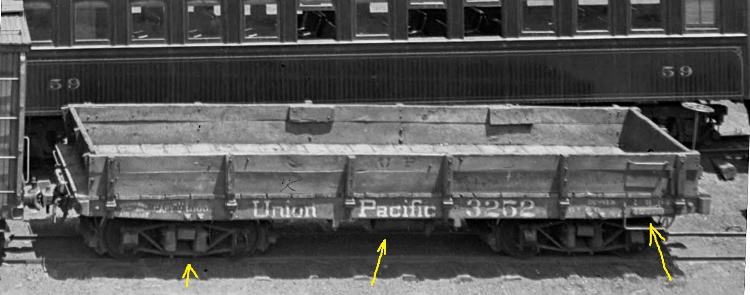 Great!! One of the few clear photos of an C&S inherited car in DL&G service, and it turns out to be another anomaly!! A beautiful photo of an odd, three car subclass. Another of Rumsfield's Unknown unknowns, now perhaps a known unknown.
Jim Courtney
Poulsbo, WA |
Re: Brake staff /cylinder confusion and mismatched trucks!!
|
This post was updated on .
Some more photos to further illustrate my confusion:
This photo of C&S 1049 is from Grandt's Narrow Gauge Pictorial VIII:, poorly reproduced here: 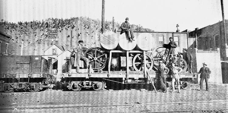 The car is listed in the roster as part of C&S series 1000-1054, 26 foot, 12 ton cars, in other words another Litchfield car. But more has happened than just re-lettering. The car was heavily shopped, either during the 1890s during the Trumbull receivership, or just after the C&S incorporation. The original 10" tapered Litchfield side sills have been replaced with straight 8" side sills butting to the end beam. The original Litchfield eight stake pocket pattern has been retained. To beef up the new frame, four 6" queen posts have been added to each of the needle beams for four truss rods without turnbuckles. The original Litchfield plate bolsters have been retained, but with 2" spacers between the bolster and the sills (yellow arrow). This is essentially a new car, from old parts, though the original 12 ton Litchfield ("type-A") trucks have been retained. Yet when the brake cylinder and hardware was reinstalled, it was mounted ass-backwards, the brake staff to the left, behind the brake cylinder which points to the right. This implies a certain standard of the day, before the St Charles cars began arriving in 1897-98. The 27 foot coal car to the left demonstrates the beefier 14 ton truck common to those cars. I don't think this car to be a one-of-a-kind anomaly, because two similar cars show up in Doug's "Pipes on Flats" photo: 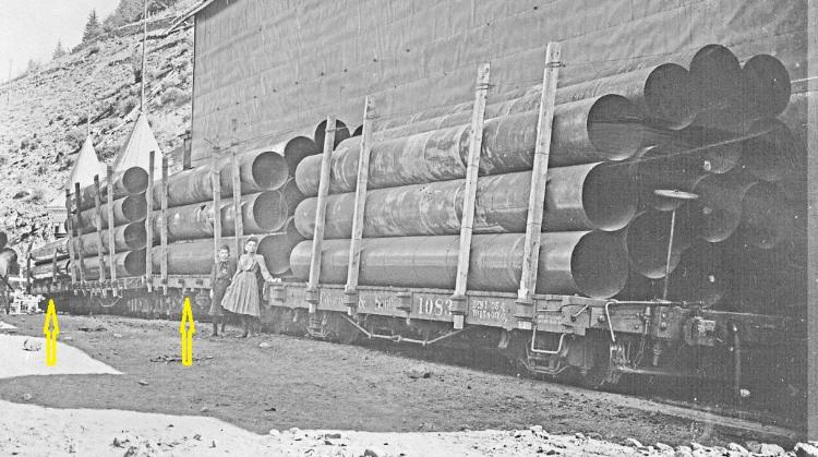 Another photo from c1901 at Kokomo shows a decent view of a Peninsular 30' coal car: 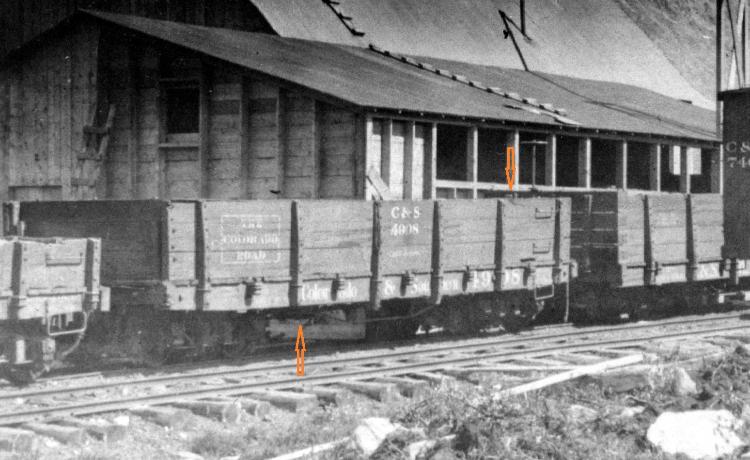 The brake cylinder is barely visible, likely on the far side of the car, but there is no brake staff on the near end of the car for it to be pointing to. A brake wheel may be present on the far end of the car, just visible in front of the St Charles coal car, but again behind the brake cylinder of number 4908. Another photo from Grandt's Narrow Gauge Pictorial VIII:, also on the Park County website, listed under Alma Junction: 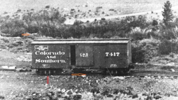 C&S number 7417 is another 27 foot, 14 ton UP built car of 1883. As there appears to be a knuckle coupler on the right end, I believe the photo dates to 1903-1904. Again the brake cylinder points to the right, though the brake staff is on the other end of the car (brake wheel just visible at orange arrow). The trucks also resemble the 14 ton coal car truck as above. 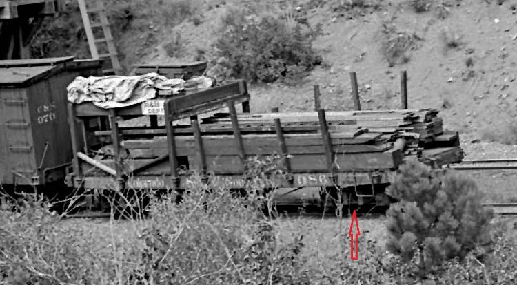 http://digital.denverlibrary.org/cdm/singleitem/collection/p15330coll22/id/78391/rec/787 B&B work flat 086 looks to be a standard Litchfield 26' flat car, but has 14 ton coal car type trucks, sometime after 1905. 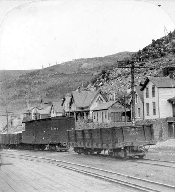 Finally, C&S 597, in Blackhawk, c1902, is a rebuilt 27 foot Tiffany reefer (horizontal lower edge of end fascia and absence of Tiffany vents). But the trucks appear to have taller transoms than those of the Peninsular coal car in the foreground, and again may be 14 ton trucks from the 27 foot coal cars. I can understand the 14 ton coal car trucks showing up under all manner of freight cars. With the large number of new 30-foot St Charles coal cars being delivered to the UPD&G and to the new C&S, the 27-foot South Park coal cars of 1882-83 likely became obsolete. They rapidly disappear from the roster, while many of the 30-foot Peninsular coal cars stayed in revenue service for another 10-15 years, some even shopped and given the block monogram lettering scheme. So, there would have been lots of surplus 14 ton coal car trucks to recycle, upgrading older cars, especially those with 12 ton Litchfield trucks. But this backward brake cylinder to brake staff arrangement still has me baffled--there are too many photos of cars with this arrangement to suggest that it was anything other than a standard practice. If anyone knows how the brake rigging actually looked, please let me know. Jim
Jim Courtney
Poulsbo, WA |
Re: Brake staff /cylinder confusion and mismatched trucks!!
|
Jim,
I wouldn't get too hung upon the "Standard Practice" of orientating the Brakecylinder travel in the direction of the handbrake end of the car for Early rolling stock. This was the result of standardization and best practice coupled to improvement with simplification that was the outgrowth of earlier designs. View these two examples of the earliest Colorado Central boxcars #1 through #10 definitely had double handbrakes, a step up from the D&RG who started with a single braked truck on their double trucked cars. See the pictures posted at http://ngdiscussion.net/phorum/read.php?1,297359,297376#msg-297376 I'd like to think this was on a/c of the mixed nature of the early CC trains-maybe/maybe not! 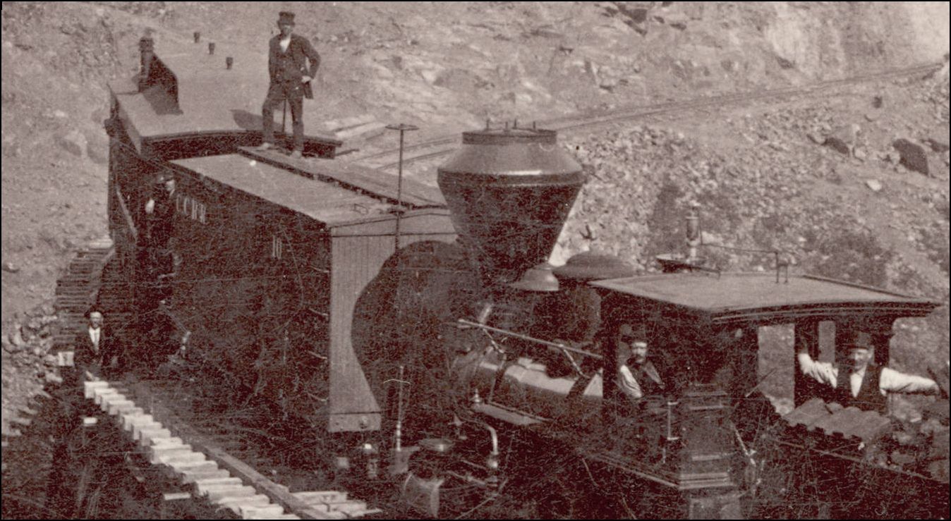 http://digital.denverlibrary.org/cdm/fullbrowser/collection/p15330coll22/id/69883/rv/singleitem/rec/121 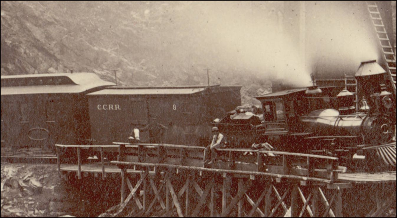 http://digital.denverlibrary.org/cdm/fullbrowser/collection/p15330coll22/id/23218/rv/singleitem/rec/268 Think along the lines of adding to what is there, by this I mean Handbrake operated Brakes per Truck(s) at first, simplified by clevised rods and levers to actuate from one Handbrake only later, shoehorn in a Vaccuumn or compressed air brake cylinder to apply the brakes mounted in the middle of the Car. The Handbrake is only attached now to the lever at the Pistonrod end and directed back to the ratchet/wheel. To have the handbrake operated from the piston end of the Brakecylinder is not that much different, just may require an extra lever operating off of a pivot point to work the travel or a longer lever elsewhere in the brakerigging at some point. Airbrake evolution has been pretty constant over the years, design improvement and safety paramount. Don't forget that there are Passenger stock (and some cabooses on other railroads) that had Brakewheels at both ends as well, and also the C&S cabooses differed in Handbrake end placement. I have noticed that a lot of the model plans don't show the rigging as it probably isn't exactly known. There were seperate Air Cylinders from the Brake Piston, depends on the Brake schedule, Manufacturer and designer preferences maybe, I can't ever recall seeing anything here on NZRailways with the combined Cyl/Piston. Mind you, I was only taught the Locomotive side with a smidgeon of car brake equipment operation. Certainly nothing what a Carman or Mechanical Engineer would know. A complex subject to cover in a few words.
UpSideDownC
in New Zealand |
Re: Brake staff /cylinder confusion and mismatched trucks!!
|
In reply to this post by Jim Courtney
Yep, another one of the great mysteries. I posed the question about the cylinder/brakestaff relationship to the DSP&P forum years ago and never got a complete answer. I even had some people tell me I was seeing things. Uh huh! I'd still love to know how the brakes were rigged.
As far as the trucks, also take a look at the pictures of the flanger (13 or 15?) in the same Narrow Gauge Pictorial / R. Robb book. Great shot of what I've started to call the Type C truck. It's far more common in the pre-C&S days than others, based on photos. When you start looking for it, it's everywhere and under all types of cars. Pictures scale out to a 4' wheelbase with 26" wheels. Doug
Doug Heitkamp
Centennial, CO |
Re: Brake staff /cylinder confusion and mismatched trucks!!
|
Doug,
I think what I am calling the 14 ton coal car trucks are the same as your "type C" truck. That is a great photo of the trucks on flanger 013 in the Grandt book. I have been modifying some old Rio Grande Models 4' wheel base Carter Brothers trucks to model this type; the transoms are a bit skinny but they come closer than anything else available. I've been staring at turn of the century wreck photos in my books the past few nights, hoping for the epiphany that will make the brake rigging clear on the inherited cars. I keep finding new photos of wrong end brake staffs, but no elusive upside down 1882-1884 built car to clarify things. Thanks for the photo reference. Jim
Jim Courtney
Poulsbo, WA |
Re: Brake staff /cylinder confusion and mismatched trucks!!
|
Indeed the brake system on the DSP&P / C&S cars is backwards. As others have mentioned, I was taught that the brake cylinder should be pointing to the brake wheel.
For another view check out the DPL Jackson, Fairplay photo CHS.J908. One can clearly see that the brake cylinder is pointing in what should be the wrong direction. In the photo 27' box car #969 appears to be no more than a year or two old, which leaves me to suspect that the brake system was installed as such when built in the Omaha shops. I was never able to positively ID the builder of the SP&LSL cars. IIRC somewhere in my notes, is a scrap that hinted that they might have been built by the United States Rolling Stock Company of Chicago. What is identified as a Litchfield builders mark is actually a Westinghouse Automatic Air Brake mark And as for the obscure lettering above Union Pacific on box car #24415 I have studied it for decades without a conclusion. When I first saw it I thought it was something similar to a circus poster. But it was too high on the car. Then when studied closer it appears to have been painted on by the railroad. And as Mr. Courtney noted, I thought the last word in the middle line say "HAY". |
Re: Brake staff /cylinder confusion and mismatched trucks!!
|
Thanks for your comments, Ron. Please visit more often, you have much to contribute here!
I think the sign on the DL&G boxcar is some early form of designated service placard for "Grain and Hay", possibly for use by a designated shipper: 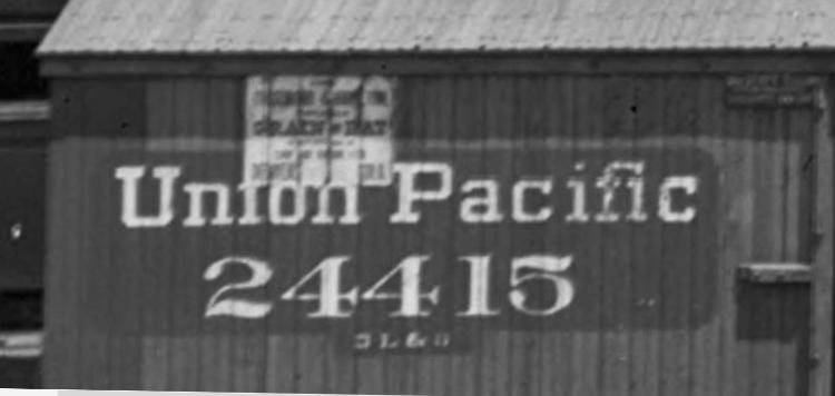 I cannot make out the shipper's or business's name though. The sign seems painted on, the paint cracked vertically at each seam of the siding boards, but the paint adhering to the groove or beadwork in the middle of each plank. There seems to be another sign or placard under the upper fascia at the door stop post. Was this car an inherited car from the DSP&P or did it come from another UP subsidiary? Could this be another owner's plate? As to the brake rigging, a few clear pictures prior to 1900 of backwards brake staff / wheel cars show the familiar anchor rod from brake reservoir to main brake lever, just peeking out under the side sills. Looks the same as on the later "phase 1" brake arrangement with right way brake staff / wheels : 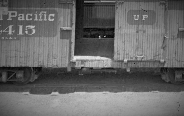 I believe that the actual brake rigging on the early backwards brake staff cars was a variation of the same system, somehow connecting the brake rod to staff differently. Still haven't figured it out though. I am trying to come up with a mechanically plausible design for modeling purposes, as we will likely never know what the real thing looked like. Jim
Jim Courtney
Poulsbo, WA |
Re: Brake staff /cylinder confusion and mismatched trucks!!
|
This post was updated on .
In reply to this post by Ron Rudnick
Enlargements from the Jackson Fairplay photo that Ron referenced (http://cdm16079.contentdm.oclc.org/cdm/singleitem/collection/p15330coll21/id/7122/rec/89:
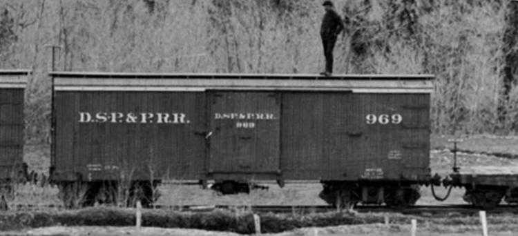 The backwards brake staff arrangement is clearly present on a nearly new car. The trucks under the boxcar are also the 14 ton coal car type, suggesting that the trucks were not recycled later, but were original equipment on the car when built in 1882-83. 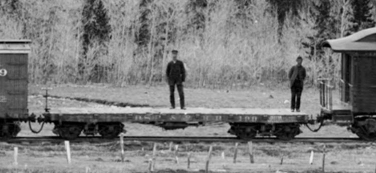 Litchfield flat car 199 shows the same brake staff relationship, trucks are the 12 ton Litchfield "type A" variety. Anyone know of a wreck photo from the 1890s or early 1900s that shows the underframe of one of the early car types?
Jim Courtney
Poulsbo, WA |
Re: Brake staff /cylinder confusion and mismatched trucks!!
|
This is a great thread - and a great observation about the position brake cylinders. Working on my Tiffany refrigerator car project led me here, and studying the images of these cars, they seem to have been set up similarly - with the brake cylinder pointing away from the brake wheel, and on the other side of the center sills.
Studying the plans that come with the Grandt line New York (C&S) air brake kit, I realized that there is a simple modification to the brake rod set up that moves the brake wheel to the opposite end of the car and puts on the other side of the center sills, as shown in these pictures. As shown in the plans, the A end live lever is retained on one end by a static rod, which bolted to the needle beam. Having recently completed a passenger car with full brake rigging, it occurred to me that if this rod is connected to the brake wheel, as it would be on a passenger car, it will move the brake wheel to the opposite end of the car and place it on the other side of the center sills, as the images in this thread show.  The other interesting thing in these images is how low the brake cylinders seem to sit on these earlier cars - it appears as if the mounting straps were put on blocking so the brake rods would clear the needle beams, which would make for an easier retrofit. With these two truss rod cars (and in the case of the 27 foot UP cars, no truss rod cars) that solution makes sense, as there are no inner truss rods to get in the way. I don't know for certain if any of this is right, but is certainly plausible. Konrad |
Re: Brake staff /cylinder confusion and mismatched trucks!!
|
This post was updated on .
Hey Konrad,
I'd forgotten about this thread. The brake rigging for the "inherited" C&S freight cars (Litchfield, UP built and Peninsular cars) is still a mystery to me. Keith and I have exchanged several emails trying to figure out how the brake systems worked and how to model them. We start from the assumption that the early brake rigging was a variation of the later St Charles and ASF cars of 1897 to 1907. That may or may not be true. First let's consider the brake rigging of the later cars and how they worked: 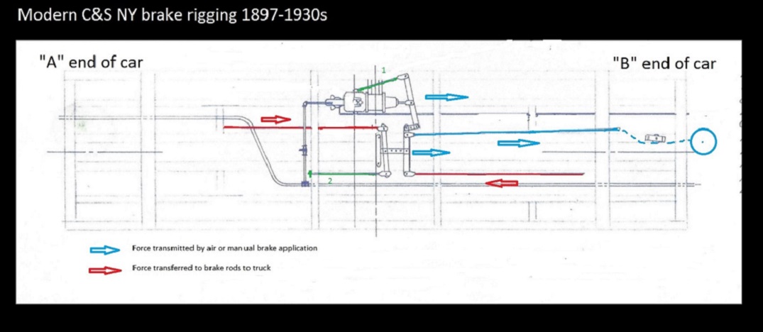 For both air brake and manual applications of the car's brakes (hand brake), the arrangement depends on two fixed brake rods that tether the system to a fixed resistance, both shown in green above. The brake cylinder rod attached to the end of the cylinder lever and the rod attached to the needle beam at the end of the "A" brake lever (Keith refers to this as a "dead man rod"). With any brake application the cylinder lever is moved toward the "B" end of the car (cylinder piston pushes, hand brake rod pulls). This force is transmitted to the two center levers connected by a bracket, which in turn cause the two brake rods to the trucks to be pulled, applying brake shoes to wheels. It is obvious how the lever to the "B" truck is caused to pull on the brake rod to that truck. But for the same force to be transmitted to the brake lever to the "A" end truck, the two center levers and their connecting bracket have to be pulled along the longitudinal axis of the car toward the B end. I had always assumed that the three levers and their connecting brackets were suspended between the needle beams, much like the accordion style brackets of old telephones. But photos of the surviving 1902 coal car at Central City show that the center lever bracket was actually suspended from a metal rail by a large metal link, allowing the system to move longitudinally in the car center-line: 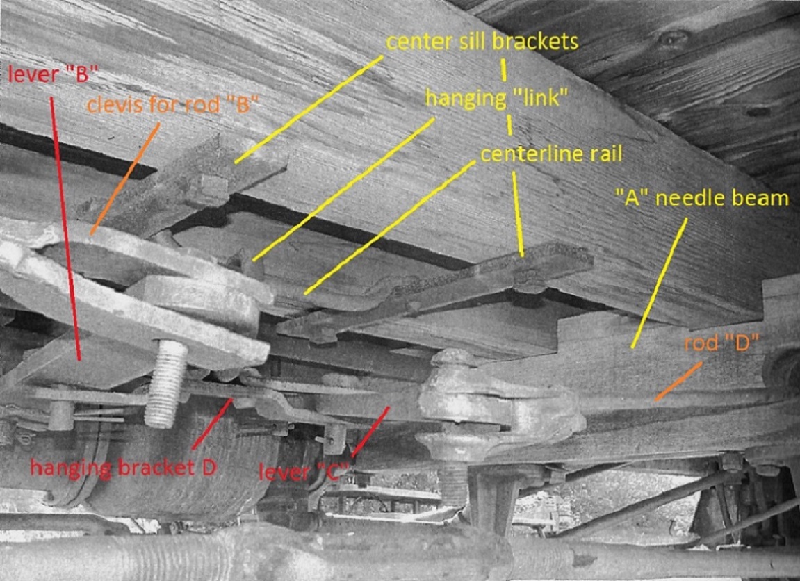 Was the inherited car's brake rigging similar? I don't know. I've yet to find a clear photo of a wrecked car's underframe. I have seen one distant, blurry photo of an overturned 27 foot boxcar, and all that can be discerned is a brake cylinder and three levers between the needle beams, but displaced due to the wreck. Based on that minimal information, I am assuming all the cars, old and new, were rigged the same, with variations. If the older cars had the brake staff and wheel on the "A" end of the car, the remaining rigging the same, then there are two possibilities: 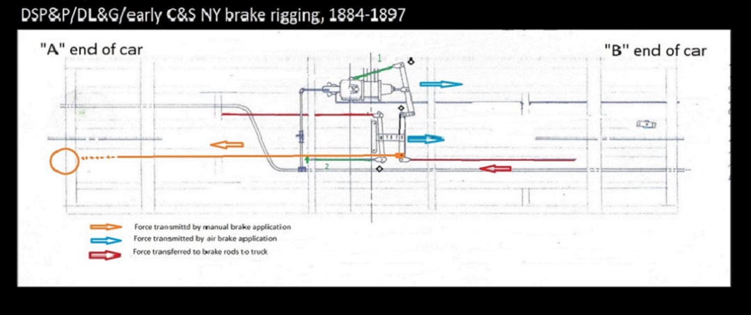 Connecting the brake rod from a staff located at the "A" end of the car, to the center lever near the "B" needle beam, would only apply brakes to the "B" truck. Possible, but not likely. Your solution I believe is the most likely, but with one difference: 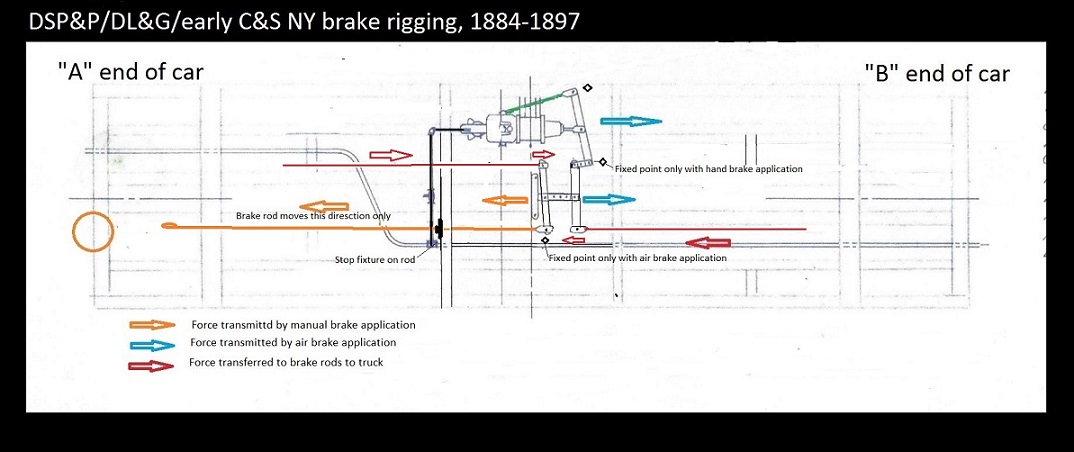 In your solution, the manual brake rod replaces the fixed "dead man" rod attached to the needle beam. But when the air brakes are applied, there has to be a fixed resistance to pull against. Is the lower brake staff, in its bracket, strong enough? And what about all the slack in the brake chain, from brake rod to brake staff, when the manual hand brake is released. My diagram proposes a "stop fixture", perhaps a large nut on a threaded section of the brake rod, occluding against a metal plate on the outside of the "A" needle beam hole. That would create two new points of fixed resistance, one for the air brake application and one for a manual brake application. My solution requires the hand brake rod to pass through the "A" needle beam via a hole, and would work on the 30' Peninsular cars with taller needle beams. But most drawings and photos appear to show the brake rods passing underneath the needle beams of the 26 and 27 foot cars, so an alternative stop fixture of some sort would be required. Perhaps all the inherited cars, with their ass-backwards brake wheels, had a stop fixture of sorts attached to the metal strap "A" bolster, at the point that the brake rod passed just underneath the bolster. If so, then they would be hidden by the "A" truck side frame, pretty much invisible, and your solution would work for modeling purposes. Who knows???  Any mechanical engineers or real railroaders in the group care to opine? And, since no one knows for sure, Konrad, you could likely model it any way you see fit! 
Jim Courtney
Poulsbo, WA |
Re: Brake staff /cylinder confusion -- 1900 C&S stock car at museum.
|
Earlier this week, Keith was kind enough to stop at the Museum in Golden and poke around under the Phase 1 (built 1900) stock car.
One of his photos illustrates a variation of how the suspended center bracket and brake levers was mounted to the two center sills. (Keith's photo was of excellent quality, I just had to play with the contrast and brightness illustrate the hardware). 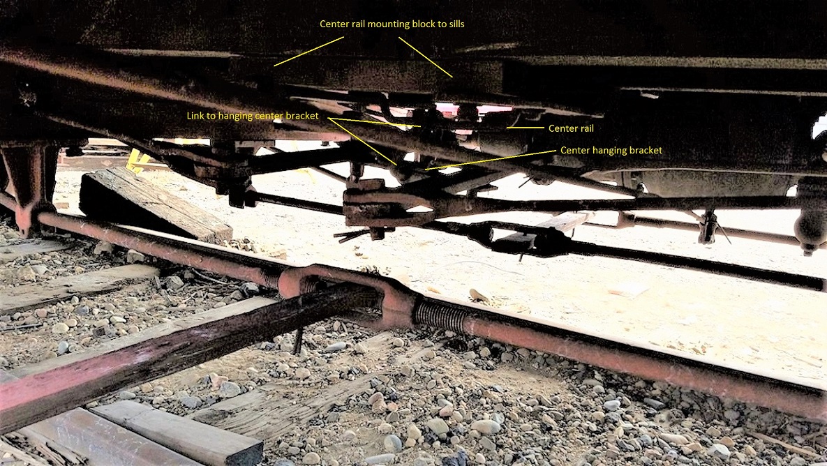 Keith Hayes photo, Colorado Railroad Museum, February 11, 2017 The center rail, from which the hanging center bracket and levers was suspended, seems to be mounted to a large 4-5" thick block that was mounted to the center sills. The link around the rail that was attached to the center bracket is visible.
Jim Courtney
Poulsbo, WA |
Re: Brake staff /cylinder confusion -- 1900 C&S stock car at museum.
|
This post was updated on .
I'm already talking myself out of my brake rigging solution, with the stop fixture.
First, looking at the threaded end of the truss rod in Keith's photo, it dawned on me that it's hard to imagine a large nut being located on a particular segment of brake rod, without the entire rod being threaded! And I doubt there was much welding going on in the 1880s-1890s. Then I reconsidered the Fairplay photo above with the nearly new UP built 27 foot boxcar:  All (three?) of the brake rods seem to pass below the needle beams, one to the right, two to the left. And there is no evidence of any truss rods, just like the hi-res photos that Todd Hacket posted of one of the 27 foot Tiffany reefer, at the Washington Spur wreck: 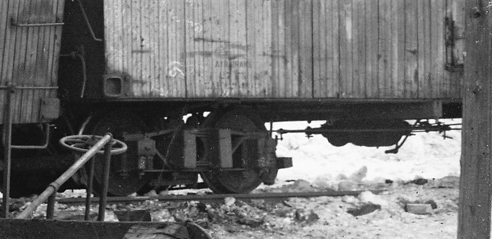 If there is a "stop fixture" it must be up near the A end of the car, hidden by the truck--of course the photographer at the Washington Spur wreck chose not to include the A end of the 27 foot reefer, where we might see something to resolve this. 
Or, maybe my first diagram, with the brake rod from the "A" end brake staff and attaching to the brake lever for only one truck, is the most feasible explanation. As Chris pointed out earlier in the thread, there was a variety of early hand brake applications, with single brake wheel / staffs attached to single truck's brakes, etc.
Jim Courtney
Poulsbo, WA |
Re: Brake staff /cylinder confusion -- 1900 C&S stock car at museum.
|
Jim, while I do not have a answer to your particular dilemma at the moment, it would not be any stretch of the imagination to visualise a blind step-keyed boss casting in place of the Nut you're suggesting.
UpSideDownC
in New Zealand |
Re: Brake staff /cylinder confusion -- 1900 C&S stock car at museum.
|
Good point, Chris.
A casting that could be bolted to the brake rod? From the photos available, though, seems to me that such a "stop" was more likely hidden up around the A end bolster. For modeling purposes, Konrad's scheme seems to make most sense. Doesn't model a hypothetical fixture based on function, that may or may not be there. Meanwhile, I'll continue to search for the Holy Grail of South Park photos--an sharp underframe view of one of the wrecked 27 foot house cars. BTW, all those brake rigging moving joints seem to be held in place with bolts, dropping down through the levers and brackets, secured below with cotter pins. How does one model S scale cotter pins!?
Jim Courtney
Poulsbo, WA |
Re: Brake staff /cylinder confusion -- 1900 C&S stock car at museum.
|
Jim and I have been exchanging e-mails on the brake system for over a year now as we have been developing the Phase I kitbash with NY brakes. Poole and Grandt provided an excellent start to the brake linkage, but the connection of the two live levers created a mystery of motion for me. I have been trying to get to the surviving Phase I cars in Central or Golden to investigate for myself and found myself in Golden last week as Jim reports.
First, I am modelling the 30s, so have less interest in the late 19th century cars than Jim and others have. But, the link between the A and B end live levers confounded me. Investigating the surviving stock car at CRRM confirmed how things were modified to work. 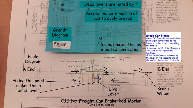 First off, as the folks at CRRM shared about the restoration of Uintah combine 50, initially the assumption was that this was a D&RGW car. In fact, it was not, and a number of the details vary. I confess, I approached the C&S brake rigging the same way, and therein the drawings confounded me. (While the railroads all followed standard practices, execution varied to some degree--the framing of the end platforms of Pullman, D&RG and C&S cars, while similar is different!) First off, it was unclear how point z (in orange) is attached. In fact, this is a bolted connection (bolted only on the face of the needle beam opposite the queen post). This causes the opposite end of the rod to function as a fixed point (though only in tension on the stock car, as the near side is not bolted to fix the rod relative to the needle beam. In any case, when the rod is in tension the brakes are being applied, and that is what counts. Lever x (colored blue) was my next confusion. This is a fabricated lever with pinned connections to the live levers (I call them live levers because they move--a dead lever is fixed on one end) on either side. It is hard to explain (and I am not sure why there need to be two live levers when the motion of one might do the trick), but I am now convinced lever x does transmit the motion between the two live levers. In person this is a really complicated part (don't waste your time trying to model it in less than 1:20.3), composed of a top plate and bottom plate forged to be riveted together in the middle and forked at the ends to grab the live levers. Now part of the mystery for me is part y (orange). This appears to be based on the hangers used by the D&RGW to fix one end of the live levers. This part does not exist--so just white it out on all your drawings! In fact, lever x is supported by a chain link from a (let's call it a) grab iron above. Thus x supports the linkage on either side and can slide along the length of the car. So...when the brakes are applied (either from the cylinder or the brake wheel) the motion is transferred on each rod (and lever) as the arrows indicate, causing the brake shoes to come in contact with the wheels. Next time I am at the Museum, I will snap a better photo of the x lever and its suspension so some of you intrepid modelers can take this on at scale. And...maybe I will try to build a 1:20.3 model some day with working brakes and scale cotter pins and figure out how to post a video so you can all see how this works. It would all be a lot easier if we could get the Museum to place a giant mirror on the rails and apply the brakes! 
Keith Hayes
Leadville in Sn3 |
Re: Brake staff /cylinder confusion -- 1900 C&S stock car at museum.
|
Oh, and an important point:
When studying the motion in brake rigging caused by the brake wheel, remember that the brake cylinder is inactive and this becomes fixed point/ dead lever. (and in my previous post, there are not really two live levers, because the lever on the A end of the car is fixed to the needle beam and really is a dead lever). Flame on!
Keith Hayes
Leadville in Sn3 |
Re: Brake staff /cylinder confusion -- 1900 C&S stock car at museum.
|
Keith,
just a little clarification, the anchor rod on the side of the Brake cyl. is the dead lever, that's its purpose. The brake piston rod is floating without air, remember that the air moves the piston, the cylinder return spring pulls it back as the air is released. The piston rod has to move during the application of the handbrake. As for photographing the undersides, might I suggest that you either use a selfie stick since everyone has phone cameras thesedays besides myself or pick up a cheap large hall mirror from Home Depot or other big box store on your way up to Golden. That way you can position it to get the pictures you need at an angle that won't get you dirty.  Besides, you'll then have a pressy for your missus when you get back. Besides, you'll then have a pressy for your missus when you get back. 
UpSideDownC
in New Zealand |
Re: Brake staff /cylinder confusion -- 1900 C&S stock car at museum.
|
In reply to this post by Keith Hayes
Keith and Jim, thanks so much for this thread- I've been wondering about this too. I'm very glad to see that part "Y" did not exist as in the Grandt diagram. I didn't include a part like this on the 1902 coal car I'm building because I couldn't understand what it would do. I was wondering, though, if it might be part of a bracket for a suspension of the central link. Your photos show this clearly, so that puzzle is solved, thanks!!
As to the handbrake though, now I'm even more confused. If indeed the cylinder rod cannot move unless the air is activated, then how can the handbrake work in the modern rig, when it is attached to the essentially fixed lever end that is enforced by the non-moving cylinder? As to the older rig, I think Konrad's suggestion makes perfect sense, with some sort of additional stop as Jim has suggested. May I suggest that the stop could have been as simple as a second piece of chain, attached to the end of the brake rod where the chain to the brake staff is attached, but leading to a fixed point, perhaps on the bolster or the frame end beam. This second piece of chain would hold the rod tension when the air is applied, and just go slack when the handbrake chain is pulled. In any case, I agree with Jim that whatever fulfilled this function was likely hidden in the bolster/truck area, so on a model could just be left out- at least until Jim finds that holy grail of photos! If my suggestion were correct, then maybe an extra bolt head or two on the A end of the car end could betray the attachment point for a second piece of chain…? Okay, now to confuse this further: Konrad's/Jim's A end handbrake rod would only work properly if indeed the cylinder enforces a fixed point at the lever end it is attached to. So this arrangement and the modern one to the B end seem mutually exclusive in light of my question above- if the cylinder makes a fixed point, A end works and B end doesn't, while if the cylinder can move, B end works and A end doesn't. No? help!!? John John Greenly Lansing, NY
John Greenly
Lansing, NY |
«
Return to C&Sng Discussion Forum
|
1 view|%1 views
| Free forum by Nabble | Edit this page |

