Re: Brake staff /cylinder confusion -- 1900 C&S stock car at museum.
Posted by Keith Hayes on Feb 18, 2017; 6:42pm
URL: http://c-sng-discussion-forum.254.s1.nabble.com/Brake-staff-cylinder-confusion-and-mismatched-trucks-tp3464p7725.html
Jim and I have been exchanging e-mails on the brake system for over a year now as we have been developing the Phase I kitbash with NY brakes. Poole and Grandt provided an excellent start to the brake linkage, but the connection of the two live levers created a mystery of motion for me. I have been trying to get to the surviving Phase I cars in Central or Golden to investigate for myself and found myself in Golden last week as Jim reports.
First, I am modelling the 30s, so have less interest in the late 19th century cars than Jim and others have. But, the link between the A and B end live levers confounded me. Investigating the surviving stock car at CRRM confirmed how things were modified to work.
First off, as the folks at CRRM shared about the restoration of Uintah combine 50, initially the assumption was that this was a D&RGW car. In fact, it was not, and a number of the details vary. I confess, I approached the C&S brake rigging the same way, and therein the drawings confounded me. (While the railroads all followed standard practices, execution varied to some degree--the framing of the end platforms of Pullman, D&RG and C&S cars, while similar is different!)
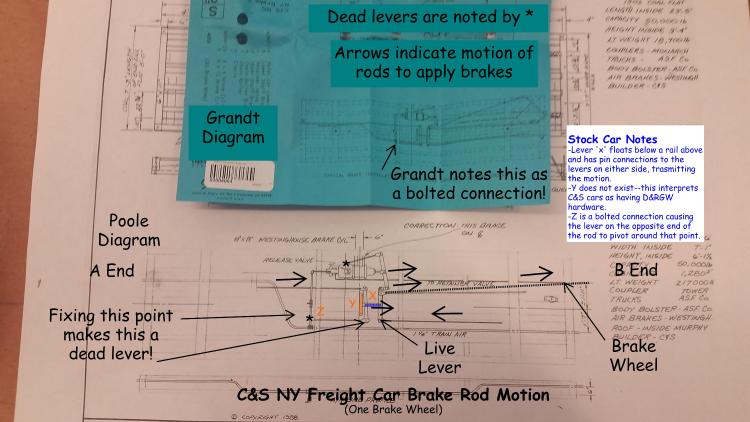
First off, it was unclear how point z (in orange) is attached. In fact, this is a bolted connection (bolted only on the face of the needle beam opposite the queen post). This causes the opposite end of the rod to function as a fixed point (though only in tension on the stock car, as the near side is not bolted to fix the rod relative to the needle beam. In any case, when the rod is in tension the brakes are being applied, and that is what counts.
Lever x (colored blue) was my next confusion. This is a fabricated lever with pinned connections to the live levers (I call them live levers because they move--a dead lever is fixed on one end) on either side. It is hard to explain (and I am not sure why there need to be two live levers when the motion of one might do the trick), but I am now convinced lever x does transmit the motion between the two live levers. In person this is a really complicated part (don't waste your time trying to model it in less than 1:20.3), composed of a top plate and bottom plate forged to be riveted together in the middle and forked at the ends to grab the live levers.
Now part of the mystery for me is part y (orange). This appears to be based on the hangers used by the D&RGW to fix one end of the live levers. This part does not exist--so just white it out on all your drawings! In fact, lever x is supported by a chain link from a (let's call it a) grab iron above. Thus x supports the linkage on either side and can slide along the length of the car.
So...when the brakes are applied (either from the cylinder or the brake wheel) the motion is transferred on each rod (and lever) as the arrows indicate, causing the brake shoes to come in contact with the wheels.
Next time I am at the Museum, I will snap a better photo of the x lever and its suspension so some of you intrepid modelers can take this on at scale. And...maybe I will try to build a 1:20.3 model some day with working brakes and scale cotter pins and figure out how to post a video so you can all see how this works. It would all be a lot easier if we could get the Museum to place a giant mirror on the rails and apply the brakes!
URL: http://c-sng-discussion-forum.254.s1.nabble.com/Brake-staff-cylinder-confusion-and-mismatched-trucks-tp3464p7725.html
Jim and I have been exchanging e-mails on the brake system for over a year now as we have been developing the Phase I kitbash with NY brakes. Poole and Grandt provided an excellent start to the brake linkage, but the connection of the two live levers created a mystery of motion for me. I have been trying to get to the surviving Phase I cars in Central or Golden to investigate for myself and found myself in Golden last week as Jim reports.
First, I am modelling the 30s, so have less interest in the late 19th century cars than Jim and others have. But, the link between the A and B end live levers confounded me. Investigating the surviving stock car at CRRM confirmed how things were modified to work.
First off, as the folks at CRRM shared about the restoration of Uintah combine 50, initially the assumption was that this was a D&RGW car. In fact, it was not, and a number of the details vary. I confess, I approached the C&S brake rigging the same way, and therein the drawings confounded me. (While the railroads all followed standard practices, execution varied to some degree--the framing of the end platforms of Pullman, D&RG and C&S cars, while similar is different!)
First off, it was unclear how point z (in orange) is attached. In fact, this is a bolted connection (bolted only on the face of the needle beam opposite the queen post). This causes the opposite end of the rod to function as a fixed point (though only in tension on the stock car, as the near side is not bolted to fix the rod relative to the needle beam. In any case, when the rod is in tension the brakes are being applied, and that is what counts.
Lever x (colored blue) was my next confusion. This is a fabricated lever with pinned connections to the live levers (I call them live levers because they move--a dead lever is fixed on one end) on either side. It is hard to explain (and I am not sure why there need to be two live levers when the motion of one might do the trick), but I am now convinced lever x does transmit the motion between the two live levers. In person this is a really complicated part (don't waste your time trying to model it in less than 1:20.3), composed of a top plate and bottom plate forged to be riveted together in the middle and forked at the ends to grab the live levers.
Now part of the mystery for me is part y (orange). This appears to be based on the hangers used by the D&RGW to fix one end of the live levers. This part does not exist--so just white it out on all your drawings! In fact, lever x is supported by a chain link from a (let's call it a) grab iron above. Thus x supports the linkage on either side and can slide along the length of the car.
So...when the brakes are applied (either from the cylinder or the brake wheel) the motion is transferred on each rod (and lever) as the arrows indicate, causing the brake shoes to come in contact with the wheels.
Next time I am at the Museum, I will snap a better photo of the x lever and its suspension so some of you intrepid modelers can take this on at scale. And...maybe I will try to build a 1:20.3 model some day with working brakes and scale cotter pins and figure out how to post a video so you can all see how this works. It would all be a lot easier if we could get the Museum to place a giant mirror on the rails and apply the brakes!
Keith Hayes
Leadville in Sn3
Leadville in Sn3
| Free forum by Nabble | Edit this page |