Re: Brake staff /cylinder confusion and mismatched trucks!!
Posted by Jim Courtney on Feb 17, 2017; 9:11pm
URL: http://c-sng-discussion-forum.254.s1.nabble.com/Brake-staff-cylinder-confusion-and-mismatched-trucks-tp3464p7710.html
Hey Konrad,
I'd forgotten about this thread. The brake rigging for the "inherited" C&S freight cars (Litchfield, UP built and Peninsular cars) is still a mystery to me. Keith and I have exchanged several emails trying to figure out how the brake systems worked and how to model them.
We start from the assumption that the early brake rigging was a variation of the later St Charles and ASF cars of 1897 to 1907. That may or may not be true.
First let's consider the brake rigging of the later cars and how they worked:
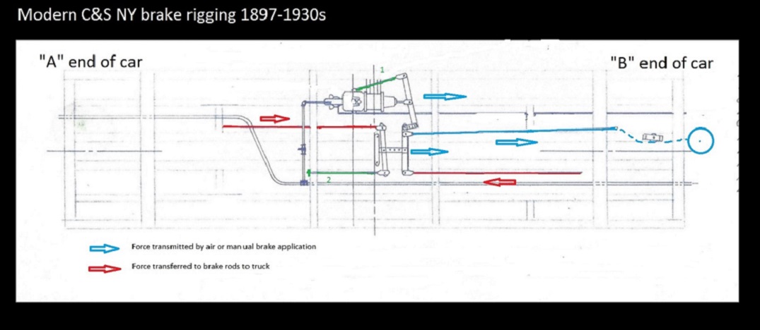
For both air brake and manual applications of the car's brakes (hand brake), the arrangement depends on two fixed brake rods that tether the system to a fixed resistance, both shown in green above. The brake cylinder rod attached to the end of the cylinder lever and the rod attached to the needle beam at the end of the "A" brake lever (Keith refers to this as a "dead man rod").
With any brake application the cylinder lever is moved toward the "B" end of the car (cylinder piston pushes, hand brake rod pulls). This force is transmitted to the two center levers connected by a bracket, which in turn cause the two brake rods to the trucks to be pulled, applying brake shoes to wheels.
It is obvious how the lever to the "B" truck is caused to pull on the brake rod to that truck. But for the same force to be transmitted to the brake lever to the "A" end truck, the two center levers and their connecting bracket have to be pulled along the longitudinal axis of the car toward the B end.
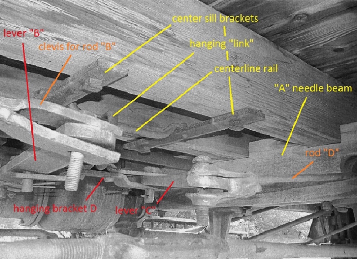
I had always assumed that the three levers and their connecting brackets were suspended between the needle beams, much like the accordion style brackets of old telephones. But photos of the surviving 1902 coal car at Central City show that the center lever bracket was actually suspended from a metal rail by a large metal link, allowing the system to move longitudinally in the car center-line:
Was the inherited car's brake rigging similar? I don't know. I've yet to find a clear photo of a wrecked car's underframe. I have seen one distant, blurry photo of an overturned 27 foot boxcar, and all that can be discerned is a brake cylinder and three levers between the needle beams, but displaced due to the wreck. Based on that minimal information, I am assuming all the cars, old and new, were rigged the same, with variations.
If the older cars had the brake staff and wheel on the "A" end of the car, the remaining rigging the same, then there are two possibilities:
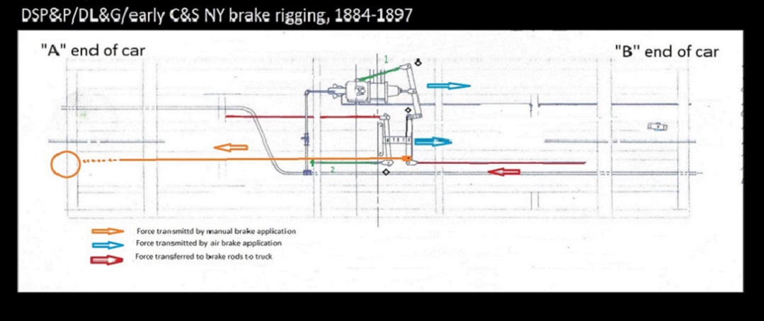
Connecting the brake rod from a staff located at the "A" end of the car, to the center lever near the "B" needle beam, would only apply brakes to the "B" truck. Possible, but not likely.
Your solution I believe is the most likely, but with one difference:
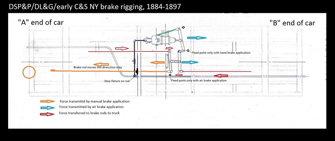
In your solution, the manual brake rod replaces the fixed "dead man" rod attached to the needle beam. But when the air brakes are applied, there has to be a fixed resistance to pull against. Is the lower brake staff, in its bracket, strong enough? And what about all the slack in the brake chain, from brake rod to brake staff, when the manual hand brake is released.
My diagram proposes a "stop fixture", perhaps a large nut on a threaded section of the brake rod, occluding against a metal plate on the outside of the "A" needle beam hole. That would create two new points of fixed resistance, one for the air brake application and one for a manual brake application.
My solution requires the hand brake rod to pass through the "A" needle beam via a hole, and would work on the 30' Peninsular cars with taller needle beams. But most drawings and photos appear to show the brake rods passing underneath the needle beams of the 26 and 27 foot cars, so an alternative stop fixture of some sort would be required.
Perhaps all the inherited cars, with their ass-backwards brake wheels, had a stop fixture of sorts attached to the metal strap "A" bolster, at the point that the brake rod passed just underneath the bolster. If so, then they would be hidden by the "A" truck side frame, pretty much invisible, and your solution would work for modeling purposes. Who knows???
Any mechanical engineers or real railroaders in the group care to opine?
And, since no one knows for sure, Konrad, you could likely model it any way you see fit!
URL: http://c-sng-discussion-forum.254.s1.nabble.com/Brake-staff-cylinder-confusion-and-mismatched-trucks-tp3464p7710.html
Hey Konrad,
I'd forgotten about this thread. The brake rigging for the "inherited" C&S freight cars (Litchfield, UP built and Peninsular cars) is still a mystery to me. Keith and I have exchanged several emails trying to figure out how the brake systems worked and how to model them.
We start from the assumption that the early brake rigging was a variation of the later St Charles and ASF cars of 1897 to 1907. That may or may not be true.
First let's consider the brake rigging of the later cars and how they worked:
For both air brake and manual applications of the car's brakes (hand brake), the arrangement depends on two fixed brake rods that tether the system to a fixed resistance, both shown in green above. The brake cylinder rod attached to the end of the cylinder lever and the rod attached to the needle beam at the end of the "A" brake lever (Keith refers to this as a "dead man rod").
With any brake application the cylinder lever is moved toward the "B" end of the car (cylinder piston pushes, hand brake rod pulls). This force is transmitted to the two center levers connected by a bracket, which in turn cause the two brake rods to the trucks to be pulled, applying brake shoes to wheels.
It is obvious how the lever to the "B" truck is caused to pull on the brake rod to that truck. But for the same force to be transmitted to the brake lever to the "A" end truck, the two center levers and their connecting bracket have to be pulled along the longitudinal axis of the car toward the B end.
I had always assumed that the three levers and their connecting brackets were suspended between the needle beams, much like the accordion style brackets of old telephones. But photos of the surviving 1902 coal car at Central City show that the center lever bracket was actually suspended from a metal rail by a large metal link, allowing the system to move longitudinally in the car center-line:
Was the inherited car's brake rigging similar? I don't know. I've yet to find a clear photo of a wrecked car's underframe. I have seen one distant, blurry photo of an overturned 27 foot boxcar, and all that can be discerned is a brake cylinder and three levers between the needle beams, but displaced due to the wreck. Based on that minimal information, I am assuming all the cars, old and new, were rigged the same, with variations.
If the older cars had the brake staff and wheel on the "A" end of the car, the remaining rigging the same, then there are two possibilities:
Connecting the brake rod from a staff located at the "A" end of the car, to the center lever near the "B" needle beam, would only apply brakes to the "B" truck. Possible, but not likely.
Your solution I believe is the most likely, but with one difference:
In your solution, the manual brake rod replaces the fixed "dead man" rod attached to the needle beam. But when the air brakes are applied, there has to be a fixed resistance to pull against. Is the lower brake staff, in its bracket, strong enough? And what about all the slack in the brake chain, from brake rod to brake staff, when the manual hand brake is released.
My diagram proposes a "stop fixture", perhaps a large nut on a threaded section of the brake rod, occluding against a metal plate on the outside of the "A" needle beam hole. That would create two new points of fixed resistance, one for the air brake application and one for a manual brake application.
My solution requires the hand brake rod to pass through the "A" needle beam via a hole, and would work on the 30' Peninsular cars with taller needle beams. But most drawings and photos appear to show the brake rods passing underneath the needle beams of the 26 and 27 foot cars, so an alternative stop fixture of some sort would be required.
Perhaps all the inherited cars, with their ass-backwards brake wheels, had a stop fixture of sorts attached to the metal strap "A" bolster, at the point that the brake rod passed just underneath the bolster. If so, then they would be hidden by the "A" truck side frame, pretty much invisible, and your solution would work for modeling purposes. Who knows???
Any mechanical engineers or real railroaders in the group care to opine?
And, since no one knows for sure, Konrad, you could likely model it any way you see fit!
Jim Courtney
Poulsbo, WA
Poulsbo, WA
| Free forum by Nabble | Edit this page |