Re: Building Leadville Designs Coal Car / Flat Car / Cinder Car Kits in C&Sn3
Posted by Jim Courtney on Aug 28, 2024; 6:45am
URL: http://c-sng-discussion-forum.254.s1.nabble.com/Building-Leadville-Designs-Coal-Car-Flat-Car-Cinder-Car-Kits-in-C-Sn3-tp19966p20089.html
Slow but steady progress on the four car build project.
Stirrups:
The DL&G and subsequent C&S car shops (actually the same guys) fabricated their own unique corner stirrups for the narrow gauge freight cars. Instead of using steel strap, an iron or steel rod was used, about 1" in diameter, bent into a shallow squared U-shape. The left vertical was flattened at the top and bolted to the side of the car, while the right vertical was flattened on the top and then bent back 90-degrees and bolted to the bottom of the side sills. Doug Heitkamp's flat car photo is a good illustration of this type of stirrup, in common use by the DL&G/UPD&G/C&S shops until the 1907 building program began:
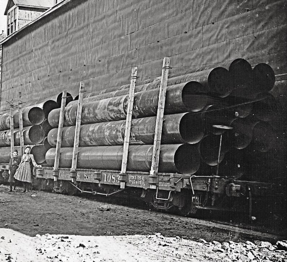
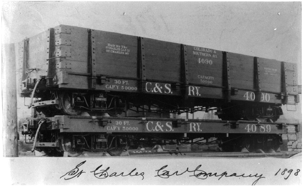
Both the 1902 coal cars and flat cars used these stirrups, 2 per car on the right end of each side. The 1898 coal cars, built by St. Charles, also used a steel rod for the stirrups, but both verticals were flattened and bolted to the side of the sill, as illustrated in another photo that Doug shared with us:
To make S-scale stirrups I use the following procedure:
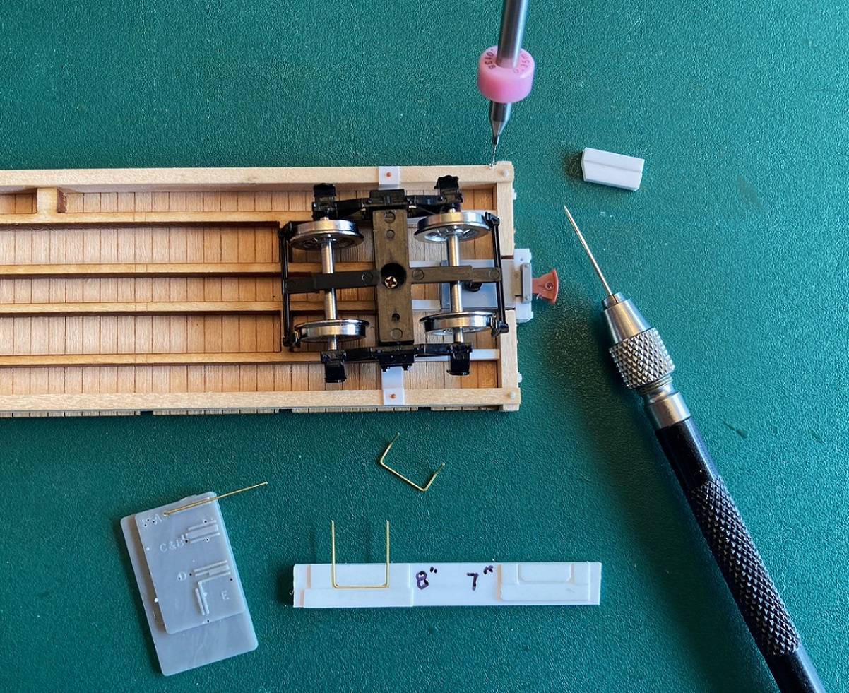
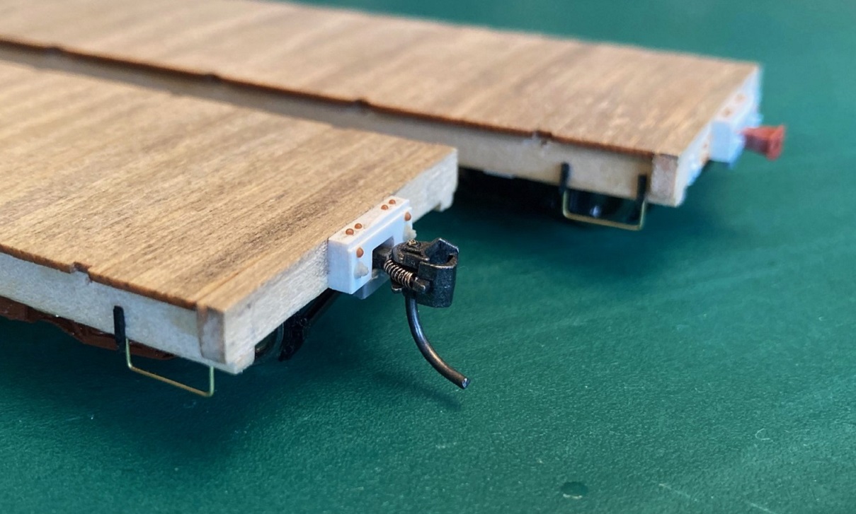
I use 0.015" brass wire, bending up square "U"s on a grab iron bending tool on 21" centers. I constructed a top bending jig from styrene, place the stirrup in the jig and bend the tops back about 45 degrees. I use a bit of 0.010" styrene glued to a thicker piece to make a scribing fence, and using my micro-awl (sewing needle in a pin vise), I scribe a line parallel to the outside of the side sill just 0.010" in. I locate the position of the holes for mounting the stirrup and drill into the wood sill at a 45 degree angle, first with a number 80 bit, then enlarging it with a 78 bit. When the two trimmed ends of the brass stirrup are inserted into the holes and seated to where the bend reaches the bottom of the sill, the wire is glued in place with ACC. The wire stirrup is then carefully straightened so it is vertical relative to the bottom of the sill:
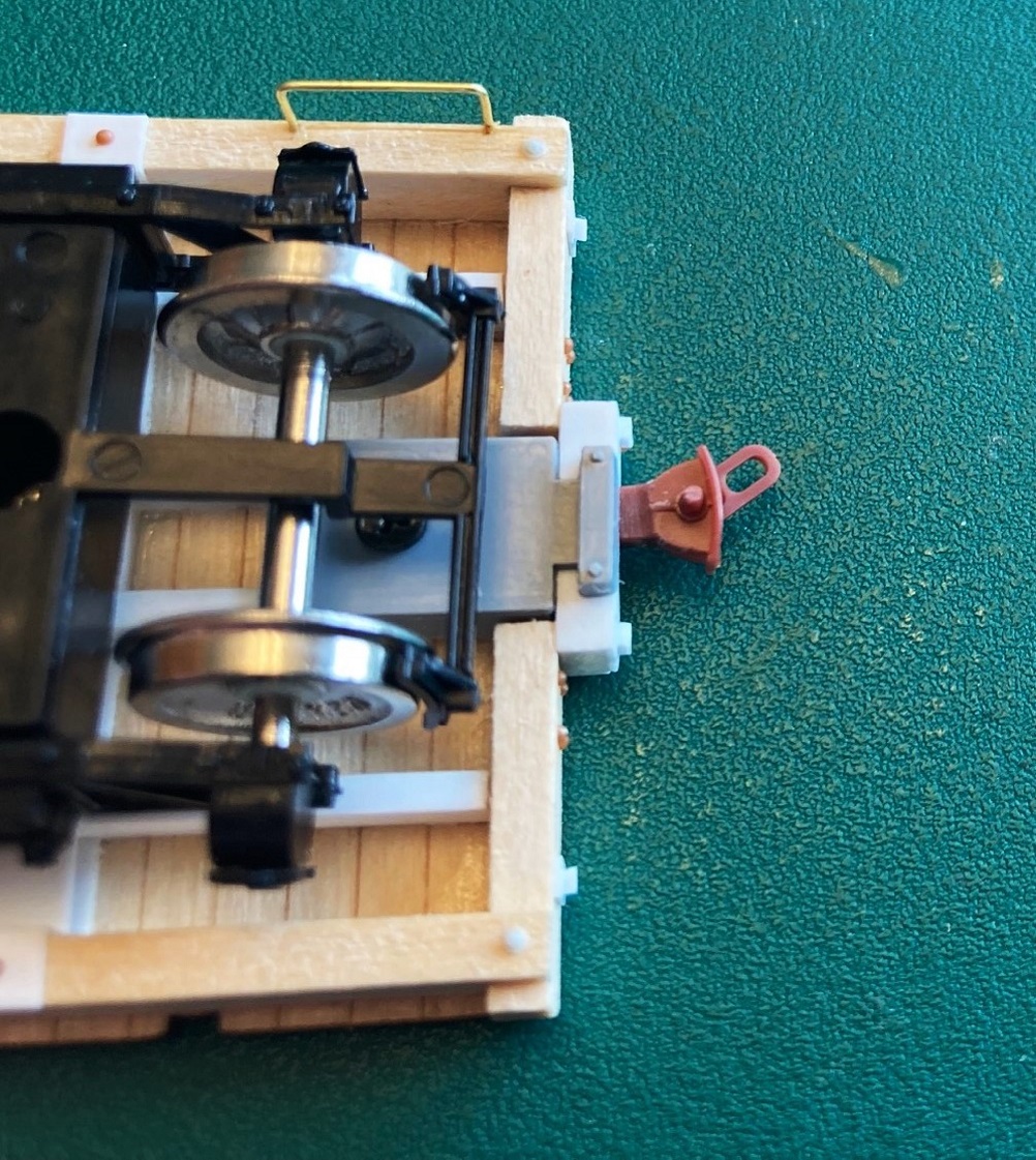
The outside of the brass wire ends up within about 0.003" from the edge of the side sill. I use the top of a PBL or Berlyn cast stirrup for the vertical attachment to the side of the sill, Evergreen strip for the fastener on the bottom of the sill:
Stakes:
There's good news and bad new about the stakes in the kit. Good news, Bill Meredith has included two complete sets of 3-D printed stakes in the kit for modeling different cars. Most folks will use the straight stakes with square cross section (4x4) to model the replacement stakes applied when the 1902 cars were refurbished for all of the Climax mill expansion business in the early 1930s. Coal car 4360 is a good example:
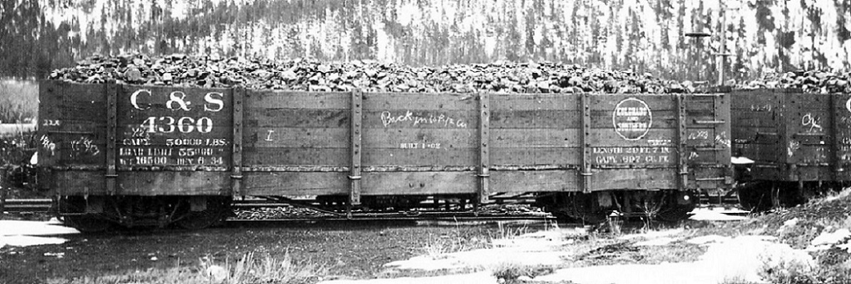
Also included is a complete set of stakes for the 1898 St. Charles coal cars, including end stakes for the as built versions. The St. Charles stakes (as noted in the builder's photo above) had a square cross section at the bottom, but above the level of the top of the deck, they tapered toward the top.
The bad news is that Bill neglected to provide the original 1902 C&S stakes. They were similar to the St. Charles stakes, but were fully tapered from bottom to top. Of course, half of this project is c1909 coal cars of this type.
Back in 2016 (eight years ago! ), when we first began discussing the building of these cars, Mike McKenzie designed Shapeways prints for all three types of stakes. I have a large stash of the 1902 original stakes and decided to use them for accuracy's sake. Up until the Shapeways bankruptcy last month, Mike offered all three types of stakes, in all three scales, in his Shapeways shop. Perhaps we need to create a "C&S 3-D Printing Consortium" to get all of the neat parts that Keith and Mike and others have designed back in production--discussion best left to another, new thread.
Mike's stakes have mounting pins printed into them. I worked out that to accurately mount the stakes vertically on the side sills, holes needed to be drilled 0.030" below the bottom of the deck and centered in the stake cut outs on the floor piece:
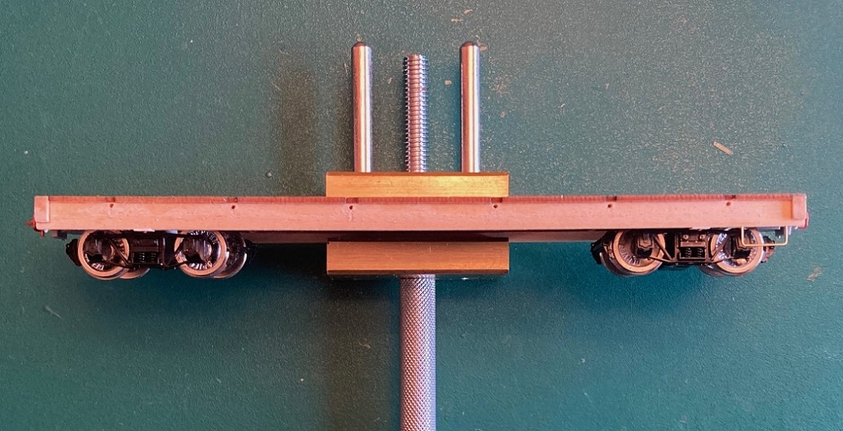
Another neat tool is my "Mini-bench vise": https://micromark.com/products/brass-mini-vise-1-1-2-inch-capacity?keyword=83441
I could carefully clamp the entire care frame in the vise, and it was heavy enough that it didn't move while marking and drilling. I used my micro-awl to locate drilling points, drilled first with a 76 drill then enlarged the holes to 0.031" with a 68 bit.
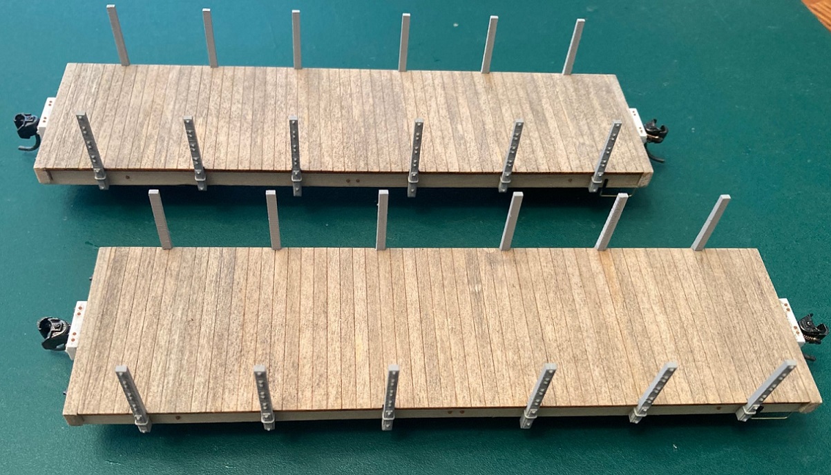
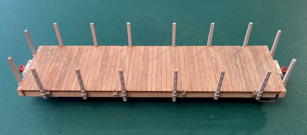
Mike's stakes, after cleaning with Bestine, have a translucent/milky color and details are hard to see. I primed all the stakes with Tamiya Fine Grey primer, to make sure I didn't accidentally attach a stake that suffered from congenital malformations--all turned out fine. The stakes are a snug press fit. I squared each one up with a small machinist's square and used ACC to attach them. I then added the final details to the end beams and the side sills, including bolt heads for the bolster and air cylinder mounts:
The mounting of Mike's stakes turned out so well that I decided to use his 1898 St. Charles tapered stakes as well. I will be saving Bill Meredith's printed a stakes for another project. The 1898 car has also had the St. Charles accessory stake pockets applied using San Juan/Grandt S scale single U-bolt stake pockets, located per the plans:
The end stakes on the 1898 car have not been glued into place yet, will save that until the side boards are installed.
The 1902 Flat Car:
The kit includes some beautiful 3-D printed stake pockets, actually correct for this car, a first in all scales. But, they are tedious to work with. I used a PBL "very fine" sprue nipper to carefully remove them from the printed stems. I again used my "mini-vise" to hold the car while positioning the individual pockets:
MEK does nothing to the printed resin, but it did make the Dullcote layer on the side sills tacky, so the little stake pockets would stay still for a minute after they were positioned. Then some very thin wire was used to apply ACC to the inside of each stake pocket, from the bottom, to secure them. After the remaining side sill and end beam details were applied, the flat car is pretty much complete from the bottom of the side sills, up:
This week I'm working on the wood sides of the three coal cars and will turn the flat car upside down and start the underframe detailing . . .
URL: http://c-sng-discussion-forum.254.s1.nabble.com/Building-Leadville-Designs-Coal-Car-Flat-Car-Cinder-Car-Kits-in-C-Sn3-tp19966p20089.html
Slow but steady progress on the four car build project.
Stirrups:
The DL&G and subsequent C&S car shops (actually the same guys) fabricated their own unique corner stirrups for the narrow gauge freight cars. Instead of using steel strap, an iron or steel rod was used, about 1" in diameter, bent into a shallow squared U-shape. The left vertical was flattened at the top and bolted to the side of the car, while the right vertical was flattened on the top and then bent back 90-degrees and bolted to the bottom of the side sills. Doug Heitkamp's flat car photo is a good illustration of this type of stirrup, in common use by the DL&G/UPD&G/C&S shops until the 1907 building program began:
Both the 1902 coal cars and flat cars used these stirrups, 2 per car on the right end of each side. The 1898 coal cars, built by St. Charles, also used a steel rod for the stirrups, but both verticals were flattened and bolted to the side of the sill, as illustrated in another photo that Doug shared with us:
To make S-scale stirrups I use the following procedure:
I use 0.015" brass wire, bending up square "U"s on a grab iron bending tool on 21" centers. I constructed a top bending jig from styrene, place the stirrup in the jig and bend the tops back about 45 degrees. I use a bit of 0.010" styrene glued to a thicker piece to make a scribing fence, and using my micro-awl (sewing needle in a pin vise), I scribe a line parallel to the outside of the side sill just 0.010" in. I locate the position of the holes for mounting the stirrup and drill into the wood sill at a 45 degree angle, first with a number 80 bit, then enlarging it with a 78 bit. When the two trimmed ends of the brass stirrup are inserted into the holes and seated to where the bend reaches the bottom of the sill, the wire is glued in place with ACC. The wire stirrup is then carefully straightened so it is vertical relative to the bottom of the sill:
The outside of the brass wire ends up within about 0.003" from the edge of the side sill. I use the top of a PBL or Berlyn cast stirrup for the vertical attachment to the side of the sill, Evergreen strip for the fastener on the bottom of the sill:
Stakes:
There's good news and bad new about the stakes in the kit. Good news, Bill Meredith has included two complete sets of 3-D printed stakes in the kit for modeling different cars. Most folks will use the straight stakes with square cross section (4x4) to model the replacement stakes applied when the 1902 cars were refurbished for all of the Climax mill expansion business in the early 1930s. Coal car 4360 is a good example:
Also included is a complete set of stakes for the 1898 St. Charles coal cars, including end stakes for the as built versions. The St. Charles stakes (as noted in the builder's photo above) had a square cross section at the bottom, but above the level of the top of the deck, they tapered toward the top.
The bad news is that Bill neglected to provide the original 1902 C&S stakes. They were similar to the St. Charles stakes, but were fully tapered from bottom to top. Of course, half of this project is c1909 coal cars of this type.
Back in 2016 (eight years ago!
), when we first began discussing the building of these cars, Mike McKenzie designed Shapeways prints for all three types of stakes. I have a large stash of the 1902 original stakes and decided to use them for accuracy's sake. Up until the Shapeways bankruptcy last month, Mike offered all three types of stakes, in all three scales, in his Shapeways shop. Perhaps we need to create a "C&S 3-D Printing Consortium" to get all of the neat parts that Keith and Mike and others have designed back in production--discussion best left to another, new thread.
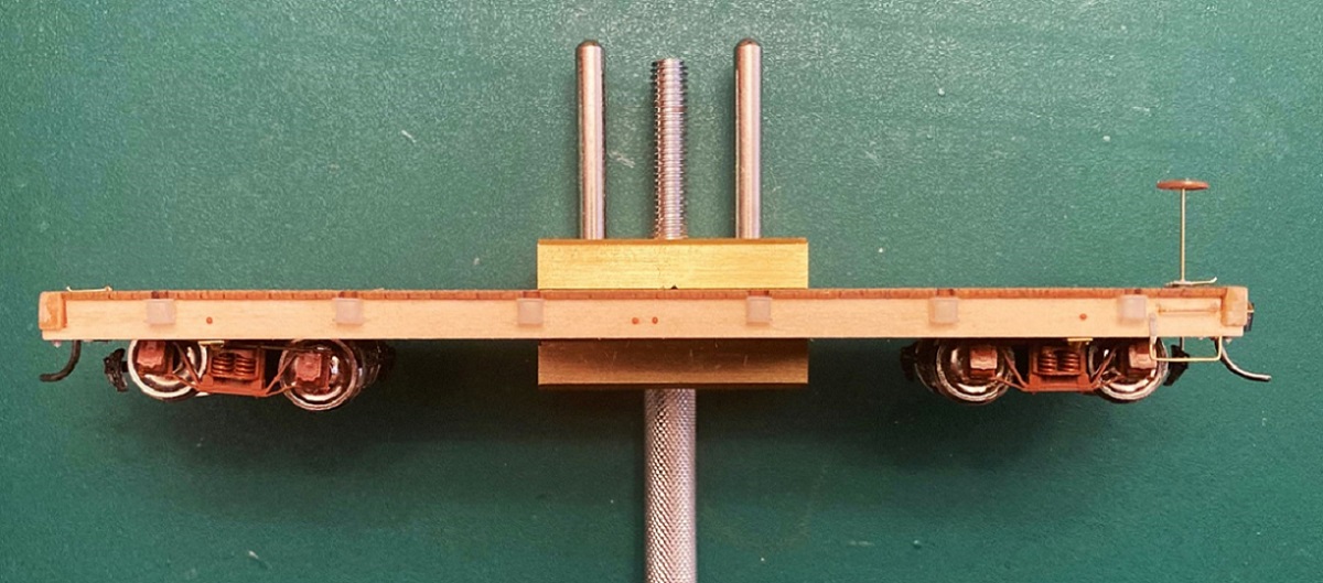
Mike's stakes have mounting pins printed into them. I worked out that to accurately mount the stakes vertically on the side sills, holes needed to be drilled 0.030" below the bottom of the deck and centered in the stake cut outs on the floor piece:
Another neat tool is my "Mini-bench vise": https://micromark.com/products/brass-mini-vise-1-1-2-inch-capacity?keyword=83441
I could carefully clamp the entire care frame in the vise, and it was heavy enough that it didn't move while marking and drilling. I used my micro-awl to locate drilling points, drilled first with a 76 drill then enlarged the holes to 0.031" with a 68 bit.
Mike's stakes, after cleaning with Bestine, have a translucent/milky color and details are hard to see. I primed all the stakes with Tamiya Fine Grey primer, to make sure I didn't accidentally attach a stake that suffered from congenital malformations--all turned out fine. The stakes are a snug press fit. I squared each one up with a small machinist's square and used ACC to attach them. I then added the final details to the end beams and the side sills, including bolt heads for the bolster and air cylinder mounts:
The mounting of Mike's stakes turned out so well that I decided to use his 1898 St. Charles tapered stakes as well. I will be saving Bill Meredith's printed a stakes for another project. The 1898 car has also had the St. Charles accessory stake pockets applied using San Juan/Grandt S scale single U-bolt stake pockets, located per the plans:
The end stakes on the 1898 car have not been glued into place yet, will save that until the side boards are installed.
The 1902 Flat Car:
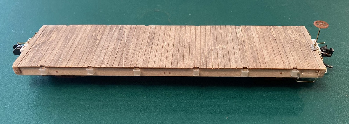
The kit includes some beautiful 3-D printed stake pockets, actually correct for this car, a first in all scales. But, they are tedious to work with. I used a PBL "very fine" sprue nipper to carefully remove them from the printed stems. I again used my "mini-vise" to hold the car while positioning the individual pockets:
MEK does nothing to the printed resin, but it did make the Dullcote layer on the side sills tacky, so the little stake pockets would stay still for a minute after they were positioned. Then some very thin wire was used to apply ACC to the inside of each stake pocket, from the bottom, to secure them. After the remaining side sill and end beam details were applied, the flat car is pretty much complete from the bottom of the side sills, up:
This week I'm working on the wood sides of the three coal cars and will turn the flat car upside down and start the underframe detailing . . .
Jim Courtney
Poulsbo, WA
Poulsbo, WA
| Free forum by Nabble | Edit this page |