Re: Building Leadville Designs Coal Car / Flat Car / Cinder Car Kits in C&Sn3
Posted by Jim Courtney on Aug 04, 2024; 7:21am
URL: http://c-sng-discussion-forum.254.s1.nabble.com/Building-Leadville-Designs-Coal-Car-Flat-Car-Cinder-Car-Kits-in-C-Sn3-tp19966p19993.html
Inspiring photos, Darel!
I started working on the Leadville Designs coal and flat car kits about a week ago, finally enough to begin sharing.
First, some tools that I now consider essentials, in addition to the usual modeling tools (knives, drills, tweezers, etc.):
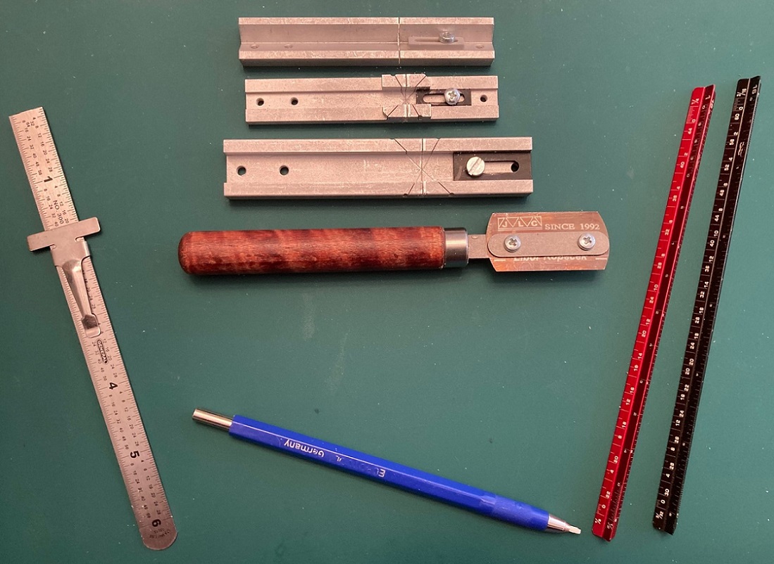
Clockwise from top: JLC razor saw and miter boxes; Mini-architects scales, Skinny fiberglass eraser, Pocket machinist's rule.
JLC Razor Saw: A very thin (0.005" thick) blade with tiny teeth on one side, very tiny teeth on the other with wood handle (https://umm-usa.com/onlinestore/product_info.php?products_id=35&osCsid=a0ed3cd1dd5066706b1694627e236860, extra blades also available https://umm-usa.com/onlinestore/product_info.php?products_id=50&osCsid=a0ed3cd1dd5066706b1694627e236860. A great little saw for cutting wood, styrene and brass.
A micro miter box set is also essential: https://umm-usa.com/onlinestore/product_info.php?cPath=21_28&products_id=8706&osCsid=a0ed3cd1dd5066706b1694627e236860. With the razor saw and miter boxes one can cut stripwood and Evergreen styrene strip and achieve precise cuts that are square in two dimensions, through the width of the strip and the depth of the cut. The adjustable stops on the micro miter boxes allow multiple, identical parts to be cut.
Mini-Architects Scale Rules: Transferring dimensions from 1/4" scale plans to S scale models can be tedious. I've been using an architect's scale for decades (3/16" scale is one twist from 1/4" scale). With these little guys, I no longer knock things (like open bottles of paint) off the workbench with the free end of a 12" rule. https://www.amazon.com/Mr-Architectural-Pocket-Engineer-Engineers/dp/B0885RP8PK/ref=sr_1_3?crid=245EF846VSTB7&dib=eyJ2IjoiMSJ9.LTMYU8ASTxy_EX6tKv1dtOTzwbSXlYm1LmEmH3ibbeKC3iu_Ej9APjqhDJgvUfHtkjQCTgrKkWfbsfA8D9rwweoXpPOQgAdfEl3Q4ruIUohbMM_j0VHHGrhnTWmSYJ1B9mPuknx-uLRTIP2hwWC8UzTagCYuSIybx8-pZm0OzzExgGH_D8BU40i2mett9SV3bk4XuzGcVuf5s3QuO66GHfajtf3-CiKreXIlJXNXkdf53nVFp4bNISIm8WjrJq1WpMzH6X-TKV_WKi5L9QsZqiGf3yDf7hC_cD-up10XsJ8.B8pciK4vKo_Y3dEKsT03T_MWIMjLjZ8LFJV_ge5m7II&dib_tag=se&keywords=mini%2Barchitectural%2Bscale%2Bruler&qid=1722719646&sprefix=mini%2Barchitect%2Caps%2C182&sr=8-3&th=1
Skinny fiberglass eraser pen: Back in the 1990s, a Gazette article made "scratch weathering" popular. PBL marketed a fiber glass eraser brush for same. I could never get it to work until my friend Dale Kreutzer recommended this little guy. It is good for removing adhesive stains (MEK on styrene and ACC on wood). It is also very handy in cleaning up solder joints on brass assemblies.
Brush: https://www.amazon.com/Extra-Fiberglass-Scratch-Brush-BRS-290-00/dp/B002RMCFZM/ref=sr_1_14?crid=1IFXYC55QV7HV&dib=eyJ2IjoiMSJ9.SMYcRl4yexvqcZodEra_oLxlmyWjxGaKbj-yX5NyOIBEFyIVhrtTxZoWy41bR6p44aCWwHXAD_exaDc81BHDuDsEg1NaJ7Vza0g7maF4gANehb26UcD0uvWLfzTZlv_Xdw7bEW0E7dXtcdlMOyDaMp_3AzjdvhptgT-ZytJDUqUzQqz5Fpg_0dkfkZtt-mhCvy41x8fAy-poS1c5DPEL6iKmfwbgkmsN08Fm3I91pDwW67mTMkXmZAisA0uBmBNpXsKqrpXS-fCowD5BkZW_wnxZnu5dt-X-BqZKhHNnGsM.fSsqekNCYLF_JHdZmAtpVDwOKbjm3QH4tYLaXq8gh_s&dib_tag=se&keywords=fibreglass+eraser&qid=1722719552&sprefix=fibreglass+eraser%2Caps%2C173&sr=8-14
Refills: https://www.amazon.com/Extra-Fiberglass-Scratch-Refills-BRS-290-01/dp/B002RMFOE6?psc=1&pd_rd_w=9JCmi&content-id=amzn1.sym.55c0153f-1fb7-42ff-8241-d1c0f3732289&pf_rd_p=55c0153f-1fb7-42ff-8241-d1c0f3732289&pf_rd_r=HYMTVQ1WN5WS60WR6RVN&pd_rd_wg=1ZKYp&pd_rd_r=c13a9135-fd0a-4f14-afcf-503ff93c8a16&ref_=sspa_dk_detail_img_1
Pocket machinists' rule: This little 6" rule has divisions of 1/32nd and 1/64th. Since S scale is 1/64"=1 scale inch, the little rule allows measuring in scale inches. The sliding pocket clip has a square upper edge, that can be used like a T-square, to lay out measures for grab iron hole locations from top or side edges. Also useful for measuring car frame height above the rail.
https://www.amazon.com/General-Tools-300-Precision-Stainless/dp/B00004T7SW/ref=sr_1_2?crid=1ZH72OVLDVUZX&dib=eyJ2IjoiMSJ9.kkp_IIu6-cHfo0hjncHRG-pAVMrGz7oFzcuTrNetfeJKmuFMbx2hoJs5Tq4i2F9PF8aZ9DAvYGbYD4o65-e39BhlYlfYvNyoJgcX3DPpFy-EJk-Tvh8KBp3WSfbPCQTqDmyR_sfSFKbJM7XRg8BRxerPd7baVM2U3I_Xcrr_Xx1AeXOs-ia9IPs3aTK1y70RKP6ib58GBs0pWSHRfMAtxbUBwDeT1H-DfFBjBUvtF1ijnX2nXxlE4RWhiheszAFswxP5yoLK9X-JyK_UNLq1WS-HQBFKUQsl9j133zW0nCo.dlFhclfjHKkr5VStkFmJVA1EFKV8ASz8MRSQ62Mkiow&dib_tag=se&keywords=pocket+machinist+rule&qid=1722719683&sprefix=pocket+machinest+rule%2Caps%2C175&sr=8-2
Okay, on to kit building.
Reference plans: For the coal cars and flat cars, I'm using Derrell Poole's 1/4" plans, PK006 (2 sheets) for the 1898 St. Charles coal cars, and PK003 (3 sheets) for the 1902 C&S built coal and flat cars. Contact me off group if you have trouble finding them.
Robert Stears also published plans for the St. Charles coal and cinder cars in the Jan/Feb 2018 issue of the Gazette.
Adhesives: I prefer to work in styrene. I've built some laser wood kits but I'm still not comfortable with the medium. I don't like wood glue. No matter how sparingly and carefully I apply it to the parts, some glue always oozes up from the joint. I end up smearing it into the wood grain or don't notice it until after I've painted the model--I hate that.
For this project I'm using a method that Bob Stears showed me at the Denver NNG Convention several years ago. All pieces of wood will get a couple of light coats of Testor's Dullcote (rattle can). The exception is any wood that will be stained for weathering, like the floor tops. The parts will then be assembled using thin ACC.
Trucks:
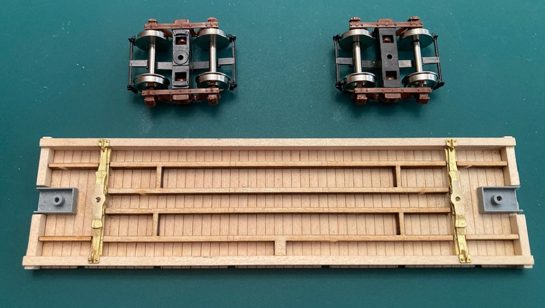
While forming a plan of assembly, I assembled six pair of old Cimarron Works truck, a pair of 1898 St. Charles trucks and five pair of 1902 ASF archbar trucks:
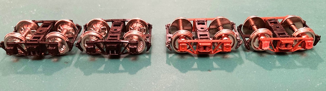
1898 trucks on left, 1902 ASH trucks on right.
I substituted code 88 wheel sets for the original wheel sets.
Cimarron Works is long defunct, but Paul Vaughn, at PVC acquired the tooling and still offers the trucks for sale in Sn3: https://pvc-sn3.com/rapidcart-2/
The 1898 trucks are TK05 and the 1902 trucks are TK01.
Floors:
Bill's floor pieces are exquisitely cut from high grade 1/32" thick basswood. All grain runs the width of the deck, with no grain "swirls" on my pieces. The grooves between the planks are laser engraved, top and bottom, and staggered a bit to suggest shiplap planks. There are engraved lines on the bottom to locate the center and intermediated sills. The floors were taped topside down to cardboard and given two coats of Dullcote. I'm going to try to stain the raw wood top of the floor after the frame is assembled, to prevent warpage / swelling.
Intermediate / Center Sills: These pieces are cut from 1/8" thick basswood for 4" x8" sills and brake hanger blocks. The right and left sides are connected like Siamese twins. They are fragile and care must be used to remove them from the thick carrier sheet. These parts also got the Dullcote treatment on all surfaces.
Side Sills and End Beams:
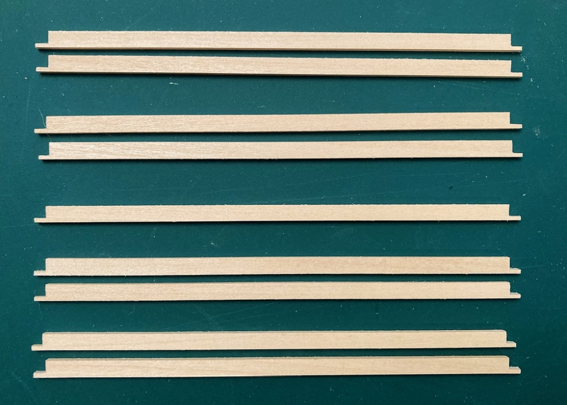
These pieces are cut from 3/32" basswood (6 scale inches thick), from side to side. When removed from the carrier sheet, I knew these pieces were going to be a problem for my as-built models. Bill has burned holes for stirrup steps and grab irons, OK for you post USSA modelers, but wrong for 1902. And the top and bottom edges have a significant taper from the laser cutting such thick wood. I felt that I would need to sand at least the top of the side sills back to a near square relationship with respect to the sides, lest the sills "toe out" when attached to the floor piece, possibly interfering with the side stake attachment. I never found out, as I decided to do something different--cut replacement notched side sills and end beams, so no holes to fill, nor surfaces to sand!
I decided to make a cutting jig for each of the pieces. For the side sills I used S scale Evergreen 4x12 strip and a top piece of 0.060 x 0.25" strip to form a channel that would fit snuggly around the Kappler S scale 6x12 in my strip wood stash. A NWSL "true sander" was used to sand the ends perfectly square and to adjust the length to exactly the length of the floor / deck--exactly 5.43". The squared ends of the channel would serve as a fence for my razor saw for making the 9" vertical cuts for the notches. Lengths of S scale Evergreen S scale 3" x 8" strip were attached to the bottoms edge of the channel on edge, to create a fence for the horizontal cut of the notches:

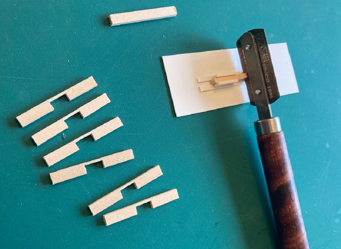
After a couple of test cuts, in about 20 minutes I was able to cut enough identical, notched sides sills for this 4 car project and a spare:
Another styrene jig was constructed to cut the 9" deep notches in the end beams. A stop was set up in my micro-miter box to the precise width of the floor and end beam blanks were cut from the 6x12 scale stripwood. The cutting jig allowed me to cut the two 9" vertical cuts for the notch, then a new, sharp #11 scalpel blade was used to carve out the wood between the two cuts, and the bottom of the notch was filed flush to the top of the scale 3" styrene strip with a small pillar file:
The new side sills and end beams got the Dullcote treatment, and then . . .
Assembly Begins:
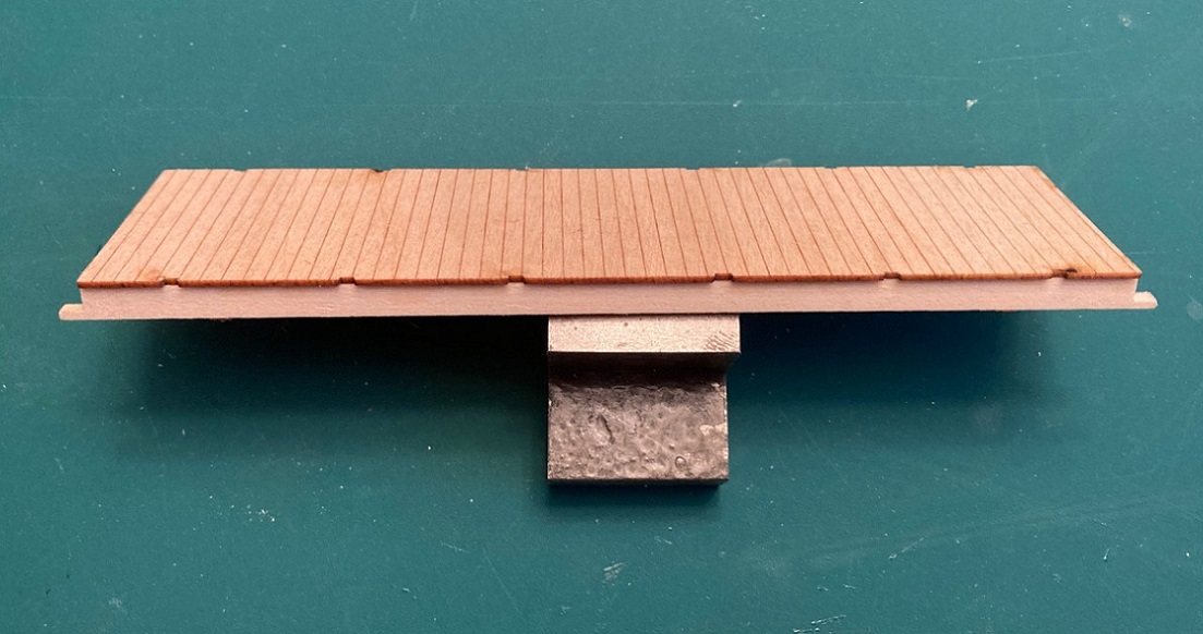
The side sills were carefully aligned to the bottom of the floor, careful to keep the outside of the sill flush with the inside of the stake pocket cutouts and flush with the ends of the floor. The sills were tacked into position with thin ACC using some small brass wire as an applicator, then ACC run down the inside sill to floor seam. When dry, excess ACC was removed from the wood with the skinny fiber glass eraser:
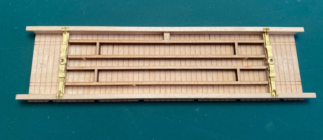
Next, the two halves of the center/intermediate sills were separated and carefully positioned per Bill's locator markings, tacked and glued with ACC, again removing excess when dry.
Bolsters:
The kits include a pair of ASF bolsters cast in brass. The CAD design for these pieces was done by our own Steve Guty, co-sponsor for the HOn3 kit. Bill has pre-drilled the bolster holes with a tap drill for 0-80 screws (but didn't both to tap them). As I prefer metric screws, I drilled out Bill's holes with a tap drill for 1.4 mm metric screws, then tapped them for the same.
There is an annoying brass sprue from the brass casting process that attaches to the inside vertical edge of one of the L-brackets for the side sill. The instructions say to carefully remove all this brass with needle files . . . nope, that will take forever. I simply cut the sprue off flush with the outside edge of the end of the bolster casting with a jewelers saw. I then used my micro razor saw to cut into the sprue, using the inside of the L bracket for the vertical cut and the inside bottom of the bracket as a fence for the horizontal cut and the residual sprue just fell out. The L-bracket was then dressed with a small pillar file to match the other.
With the frame upside down, I tried to install the bolsters between the side sills, but they didn't want to fit. No fault of Steve's design, as he drew the bolsters to precisely fit between 5" side sills, while the side sills for the kit are 6" thick. This may or may not be a problem for the On3 and HOn3 kits. So more filing of the L-brackets to remove more brass and finally they (snuggly) fit in place:
Mounting trucks and adjusting body height:
The 1898 and 1902 coal cars are real "low riders". The distance from bottom of side sills to rail top was 20" on the 1898 cars and 21" on the 1902 copies. I find this "hunkered down on the trucks" look to be very appealing.
But when the ASF trucks were mounted to the bolsters of my car, the car sat on the trucks about 4 scale inches too high. The major issue is the height of the truck bolsters, taller than prototype to allow mechanical assembly that is sturdy. My only solution was to use a flat mill file and file the car bolster bearing disc down flat, to the same height as the rest of the bolster center (sorry Steve!). This lowered they car by about 1.5 scale inches. So then I had to resort to filing the truck bolster bearing and the square plate below it off the top of the truck bolsters. This corrected the car height to 21 scale inches, rail head to bottom of side sills, just right!
Stock truck bolster on left, modified truck bolster on the right. Note that coupler draft gear boxes have ben test fitted with double sides tape.
With the bolster / truck mounting complete, I added the 4 small laser cut intermediate sill extensions from bolster to edge of floor with ACC. Then the end beams were mounted into the notches of the side sills and against the floor, tacked into place with ACC, then carefully secured with ACC. Any part of the lower side sill that protruded beyond the end beam was cut flush with the end beam.
The 6"x12" end beams stick up a bit above the top of the floor. This is good, as the real ones were 6" x 11". The top of the end beams were sanded flush with the top of the floor using sand paper on a flat surface.
Coupler mounting: All of Bill's kits make the same provision for couplers. A notched end beam (with or without end sheathing) with the bottom of the notch flush with the bottom of the floor and and empty space from bolster to end beam and between the intermediate sills. As all C&S freight cars had floors the same height above the rail (trust me on this), I've come up with my own system for mounting couplers:
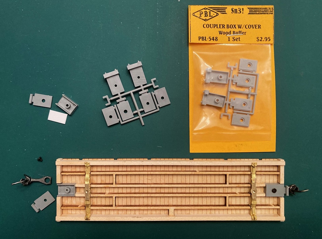
I use PBL part 548, "coupler box with covers". I use the razor saw to cut the D&RG striker block from the front of the draft gear box. Evergreen 0.030" x 0.25" strip is cut to the same length as the box and glued to the top of the box, centered. A short 1.7 mm screw is screwed into the hole in the stem of the box to cut it's own threads. I use the long cover plate with the carrier iron (to keep the coupler from drooping). The box is then glued to the underside of the floor, the front edge just a wee bit in from the outer edge of the end beam, being careful to keep the draft gear box centered (to the floor, not the notch. When dry, I insert Kadee #146 couplers (standard head, whisker couplers with long center shank) into the box, screw on the cover plate, and remount the trucks. Testing, the couplers match the same height as all my other C&S cars. Don't be concerned that the coupler head protrudes too far from the end beam. The striker block will fill that gap.
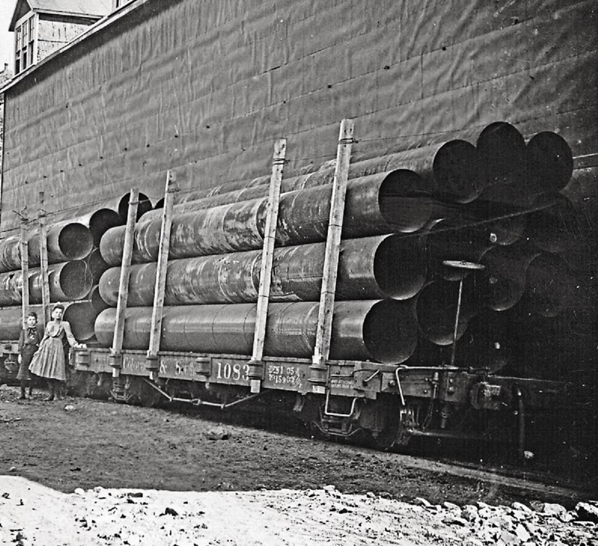
Striker blocks: This is a laser cut part, again 6" thick, again with bevel on the cut surfaces. Bill has provided an etched brass striker plate to glue onto the front surface. This may be okay for the 1898 car, but for the 1902 coal car it didn't look right. I have never seen a clear photo of the 1902 coals as built, but our late friend, Doug Heitkamp, posted this photo of one of the 1902 flat cars after automatic couplers were installed:
And another photo of a 1902 flat car taken about 1912:
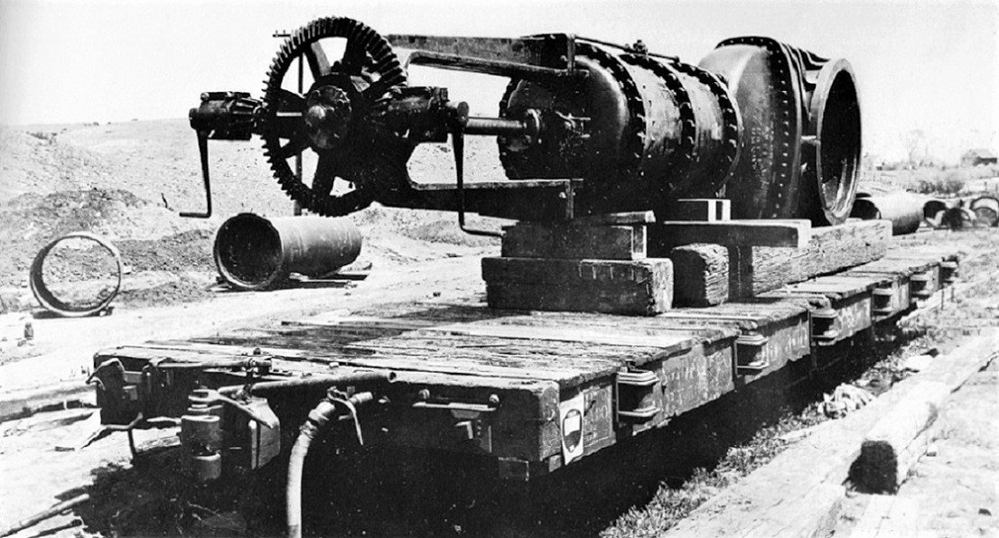
As the 1902 flat cars and coal cars left the C&S shops at the same time, I'm assuming that the end beam details are identical. The draft gear striker plate looks taller here, with the truss rod NBW below the bolt head securing the striker plate to block. As I'm still working on several of Bill's C&S boxcar kits, I have already worked out construction of the striker block in styrene, and have a large stash of precut parts:
The blocks are 3 pieces of 0.080" thick styrene glued together, then sanded flush at the ends. A piece of 0.010' x 0.156" styrene is then glued over the front of the block to represent the striker plate, the opening cut out with a sharp knife, and squared up with needle files. The truss rod NBW is Grandt #93, while Tichy rivets were used--0.030" for the striker plate, 0.025" for the four bolt heads atop the block. Before attaching the blocks to the end beams, I located and drilled out a vertical 0.020" hole for the brake staff in one of them--it is much easier to do this now than after the part is attached to the car.
Finally, the striker blocks were attached to the end beams, making sure that the one with the vertical hole was glued to the "B" end of the car:
Whew! Such a long post, hope ya'll find this helpful.
In the next week or so, I will finish building up the other three kits to this level of construction, so I can stain all the decks at the same time. Then, moving on with underframe detailing (plumbing / brake rigging and such) and finally the open box body and side stakes.
URL: http://c-sng-discussion-forum.254.s1.nabble.com/Building-Leadville-Designs-Coal-Car-Flat-Car-Cinder-Car-Kits-in-C-Sn3-tp19966p19993.html
Inspiring photos, Darel!
I started working on the Leadville Designs coal and flat car kits about a week ago, finally enough to begin sharing.
First, some tools that I now consider essentials, in addition to the usual modeling tools (knives, drills, tweezers, etc.):
Clockwise from top: JLC razor saw and miter boxes; Mini-architects scales, Skinny fiberglass eraser, Pocket machinist's rule.
JLC Razor Saw: A very thin (0.005" thick) blade with tiny teeth on one side, very tiny teeth on the other with wood handle (https://umm-usa.com/onlinestore/product_info.php?products_id=35&osCsid=a0ed3cd1dd5066706b1694627e236860, extra blades also available https://umm-usa.com/onlinestore/product_info.php?products_id=50&osCsid=a0ed3cd1dd5066706b1694627e236860. A great little saw for cutting wood, styrene and brass.
A micro miter box set is also essential: https://umm-usa.com/onlinestore/product_info.php?cPath=21_28&products_id=8706&osCsid=a0ed3cd1dd5066706b1694627e236860. With the razor saw and miter boxes one can cut stripwood and Evergreen styrene strip and achieve precise cuts that are square in two dimensions, through the width of the strip and the depth of the cut. The adjustable stops on the micro miter boxes allow multiple, identical parts to be cut.
Mini-Architects Scale Rules: Transferring dimensions from 1/4" scale plans to S scale models can be tedious. I've been using an architect's scale for decades (3/16" scale is one twist from 1/4" scale). With these little guys, I no longer knock things (like open bottles of paint) off the workbench with the free end of a 12" rule. https://www.amazon.com/Mr-Architectural-Pocket-Engineer-Engineers/dp/B0885RP8PK/ref=sr_1_3?crid=245EF846VSTB7&dib=eyJ2IjoiMSJ9.LTMYU8ASTxy_EX6tKv1dtOTzwbSXlYm1LmEmH3ibbeKC3iu_Ej9APjqhDJgvUfHtkjQCTgrKkWfbsfA8D9rwweoXpPOQgAdfEl3Q4ruIUohbMM_j0VHHGrhnTWmSYJ1B9mPuknx-uLRTIP2hwWC8UzTagCYuSIybx8-pZm0OzzExgGH_D8BU40i2mett9SV3bk4XuzGcVuf5s3QuO66GHfajtf3-CiKreXIlJXNXkdf53nVFp4bNISIm8WjrJq1WpMzH6X-TKV_WKi5L9QsZqiGf3yDf7hC_cD-up10XsJ8.B8pciK4vKo_Y3dEKsT03T_MWIMjLjZ8LFJV_ge5m7II&dib_tag=se&keywords=mini%2Barchitectural%2Bscale%2Bruler&qid=1722719646&sprefix=mini%2Barchitect%2Caps%2C182&sr=8-3&th=1
Skinny fiberglass eraser pen: Back in the 1990s, a Gazette article made "scratch weathering" popular. PBL marketed a fiber glass eraser brush for same. I could never get it to work until my friend Dale Kreutzer recommended this little guy. It is good for removing adhesive stains (MEK on styrene and ACC on wood). It is also very handy in cleaning up solder joints on brass assemblies.
Brush: https://www.amazon.com/Extra-Fiberglass-Scratch-Brush-BRS-290-00/dp/B002RMCFZM/ref=sr_1_14?crid=1IFXYC55QV7HV&dib=eyJ2IjoiMSJ9.SMYcRl4yexvqcZodEra_oLxlmyWjxGaKbj-yX5NyOIBEFyIVhrtTxZoWy41bR6p44aCWwHXAD_exaDc81BHDuDsEg1NaJ7Vza0g7maF4gANehb26UcD0uvWLfzTZlv_Xdw7bEW0E7dXtcdlMOyDaMp_3AzjdvhptgT-ZytJDUqUzQqz5Fpg_0dkfkZtt-mhCvy41x8fAy-poS1c5DPEL6iKmfwbgkmsN08Fm3I91pDwW67mTMkXmZAisA0uBmBNpXsKqrpXS-fCowD5BkZW_wnxZnu5dt-X-BqZKhHNnGsM.fSsqekNCYLF_JHdZmAtpVDwOKbjm3QH4tYLaXq8gh_s&dib_tag=se&keywords=fibreglass+eraser&qid=1722719552&sprefix=fibreglass+eraser%2Caps%2C173&sr=8-14
Refills: https://www.amazon.com/Extra-Fiberglass-Scratch-Refills-BRS-290-01/dp/B002RMFOE6?psc=1&pd_rd_w=9JCmi&content-id=amzn1.sym.55c0153f-1fb7-42ff-8241-d1c0f3732289&pf_rd_p=55c0153f-1fb7-42ff-8241-d1c0f3732289&pf_rd_r=HYMTVQ1WN5WS60WR6RVN&pd_rd_wg=1ZKYp&pd_rd_r=c13a9135-fd0a-4f14-afcf-503ff93c8a16&ref_=sspa_dk_detail_img_1
Pocket machinists' rule: This little 6" rule has divisions of 1/32nd and 1/64th. Since S scale is 1/64"=1 scale inch, the little rule allows measuring in scale inches. The sliding pocket clip has a square upper edge, that can be used like a T-square, to lay out measures for grab iron hole locations from top or side edges. Also useful for measuring car frame height above the rail.
https://www.amazon.com/General-Tools-300-Precision-Stainless/dp/B00004T7SW/ref=sr_1_2?crid=1ZH72OVLDVUZX&dib=eyJ2IjoiMSJ9.kkp_IIu6-cHfo0hjncHRG-pAVMrGz7oFzcuTrNetfeJKmuFMbx2hoJs5Tq4i2F9PF8aZ9DAvYGbYD4o65-e39BhlYlfYvNyoJgcX3DPpFy-EJk-Tvh8KBp3WSfbPCQTqDmyR_sfSFKbJM7XRg8BRxerPd7baVM2U3I_Xcrr_Xx1AeXOs-ia9IPs3aTK1y70RKP6ib58GBs0pWSHRfMAtxbUBwDeT1H-DfFBjBUvtF1ijnX2nXxlE4RWhiheszAFswxP5yoLK9X-JyK_UNLq1WS-HQBFKUQsl9j133zW0nCo.dlFhclfjHKkr5VStkFmJVA1EFKV8ASz8MRSQ62Mkiow&dib_tag=se&keywords=pocket+machinist+rule&qid=1722719683&sprefix=pocket+machinest+rule%2Caps%2C175&sr=8-2
Okay, on to kit building.
Reference plans: For the coal cars and flat cars, I'm using Derrell Poole's 1/4" plans, PK006 (2 sheets) for the 1898 St. Charles coal cars, and PK003 (3 sheets) for the 1902 C&S built coal and flat cars. Contact me off group if you have trouble finding them.
Robert Stears also published plans for the St. Charles coal and cinder cars in the Jan/Feb 2018 issue of the Gazette.
Adhesives: I prefer to work in styrene. I've built some laser wood kits but I'm still not comfortable with the medium. I don't like wood glue. No matter how sparingly and carefully I apply it to the parts, some glue always oozes up from the joint. I end up smearing it into the wood grain or don't notice it until after I've painted the model--I hate that.
For this project I'm using a method that Bob Stears showed me at the Denver NNG Convention several years ago. All pieces of wood will get a couple of light coats of Testor's Dullcote (rattle can). The exception is any wood that will be stained for weathering, like the floor tops. The parts will then be assembled using thin ACC.
Trucks:
While forming a plan of assembly, I assembled six pair of old Cimarron Works truck, a pair of 1898 St. Charles trucks and five pair of 1902 ASF archbar trucks:
1898 trucks on left, 1902 ASH trucks on right.
I substituted code 88 wheel sets for the original wheel sets.
Cimarron Works is long defunct, but Paul Vaughn, at PVC acquired the tooling and still offers the trucks for sale in Sn3: https://pvc-sn3.com/rapidcart-2/
The 1898 trucks are TK05 and the 1902 trucks are TK01.
Floors:
Bill's floor pieces are exquisitely cut from high grade 1/32" thick basswood. All grain runs the width of the deck, with no grain "swirls" on my pieces. The grooves between the planks are laser engraved, top and bottom, and staggered a bit to suggest shiplap planks. There are engraved lines on the bottom to locate the center and intermediated sills. The floors were taped topside down to cardboard and given two coats of Dullcote. I'm going to try to stain the raw wood top of the floor after the frame is assembled, to prevent warpage / swelling.
Intermediate / Center Sills: These pieces are cut from 1/8" thick basswood for 4" x8" sills and brake hanger blocks. The right and left sides are connected like Siamese twins. They are fragile and care must be used to remove them from the thick carrier sheet. These parts also got the Dullcote treatment on all surfaces.
Side Sills and End Beams:
These pieces are cut from 3/32" basswood (6 scale inches thick), from side to side. When removed from the carrier sheet, I knew these pieces were going to be a problem for my as-built models. Bill has burned holes for stirrup steps and grab irons, OK for you post USSA modelers, but wrong for 1902. And the top and bottom edges have a significant taper from the laser cutting such thick wood. I felt that I would need to sand at least the top of the side sills back to a near square relationship with respect to the sides, lest the sills "toe out" when attached to the floor piece, possibly interfering with the side stake attachment. I never found out, as I decided to do something different--cut replacement notched side sills and end beams, so no holes to fill, nor surfaces to sand!
I decided to make a cutting jig for each of the pieces. For the side sills I used S scale Evergreen 4x12 strip and a top piece of 0.060 x 0.25" strip to form a channel that would fit snuggly around the Kappler S scale 6x12 in my strip wood stash. A NWSL "true sander" was used to sand the ends perfectly square and to adjust the length to exactly the length of the floor / deck--exactly 5.43". The squared ends of the channel would serve as a fence for my razor saw for making the 9" vertical cuts for the notches. Lengths of S scale Evergreen S scale 3" x 8" strip were attached to the bottoms edge of the channel on edge, to create a fence for the horizontal cut of the notches:
After a couple of test cuts, in about 20 minutes I was able to cut enough identical, notched sides sills for this 4 car project and a spare:
Another styrene jig was constructed to cut the 9" deep notches in the end beams. A stop was set up in my micro-miter box to the precise width of the floor and end beam blanks were cut from the 6x12 scale stripwood. The cutting jig allowed me to cut the two 9" vertical cuts for the notch, then a new, sharp #11 scalpel blade was used to carve out the wood between the two cuts, and the bottom of the notch was filed flush to the top of the scale 3" styrene strip with a small pillar file:
The new side sills and end beams got the Dullcote treatment, and then . . .
Assembly Begins:
The side sills were carefully aligned to the bottom of the floor, careful to keep the outside of the sill flush with the inside of the stake pocket cutouts and flush with the ends of the floor. The sills were tacked into position with thin ACC using some small brass wire as an applicator, then ACC run down the inside sill to floor seam. When dry, excess ACC was removed from the wood with the skinny fiber glass eraser:
Next, the two halves of the center/intermediate sills were separated and carefully positioned per Bill's locator markings, tacked and glued with ACC, again removing excess when dry.
Bolsters:
The kits include a pair of ASF bolsters cast in brass. The CAD design for these pieces was done by our own Steve Guty, co-sponsor for the HOn3 kit. Bill has pre-drilled the bolster holes with a tap drill for 0-80 screws (but didn't both to tap them). As I prefer metric screws, I drilled out Bill's holes with a tap drill for 1.4 mm metric screws, then tapped them for the same.
There is an annoying brass sprue from the brass casting process that attaches to the inside vertical edge of one of the L-brackets for the side sill. The instructions say to carefully remove all this brass with needle files . . . nope, that will take forever. I simply cut the sprue off flush with the outside edge of the end of the bolster casting with a jewelers saw. I then used my micro razor saw to cut into the sprue, using the inside of the L bracket for the vertical cut and the inside bottom of the bracket as a fence for the horizontal cut and the residual sprue just fell out. The L-bracket was then dressed with a small pillar file to match the other.
With the frame upside down, I tried to install the bolsters between the side sills, but they didn't want to fit. No fault of Steve's design, as he drew the bolsters to precisely fit between 5" side sills, while the side sills for the kit are 6" thick. This may or may not be a problem for the On3 and HOn3 kits. So more filing of the L-brackets to remove more brass and finally they (snuggly) fit in place:
Mounting trucks and adjusting body height:
The 1898 and 1902 coal cars are real "low riders". The distance from bottom of side sills to rail top was 20" on the 1898 cars and 21" on the 1902 copies. I find this "hunkered down on the trucks" look to be very appealing.
But when the ASF trucks were mounted to the bolsters of my car, the car sat on the trucks about 4 scale inches too high. The major issue is the height of the truck bolsters, taller than prototype to allow mechanical assembly that is sturdy. My only solution was to use a flat mill file and file the car bolster bearing disc down flat, to the same height as the rest of the bolster center (sorry Steve!). This lowered they car by about 1.5 scale inches. So then I had to resort to filing the truck bolster bearing and the square plate below it off the top of the truck bolsters. This corrected the car height to 21 scale inches, rail head to bottom of side sills, just right!
Stock truck bolster on left, modified truck bolster on the right. Note that coupler draft gear boxes have ben test fitted with double sides tape.
With the bolster / truck mounting complete, I added the 4 small laser cut intermediate sill extensions from bolster to edge of floor with ACC. Then the end beams were mounted into the notches of the side sills and against the floor, tacked into place with ACC, then carefully secured with ACC. Any part of the lower side sill that protruded beyond the end beam was cut flush with the end beam.
The 6"x12" end beams stick up a bit above the top of the floor. This is good, as the real ones were 6" x 11". The top of the end beams were sanded flush with the top of the floor using sand paper on a flat surface.
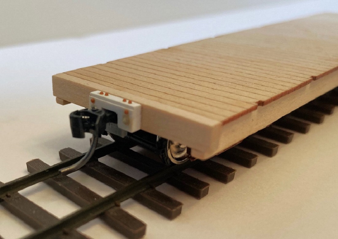
Coupler mounting: All of Bill's kits make the same provision for couplers. A notched end beam (with or without end sheathing) with the bottom of the notch flush with the bottom of the floor and and empty space from bolster to end beam and between the intermediate sills. As all C&S freight cars had floors the same height above the rail (trust me on this), I've come up with my own system for mounting couplers:
I use PBL part 548, "coupler box with covers". I use the razor saw to cut the D&RG striker block from the front of the draft gear box. Evergreen 0.030" x 0.25" strip is cut to the same length as the box and glued to the top of the box, centered. A short 1.7 mm screw is screwed into the hole in the stem of the box to cut it's own threads. I use the long cover plate with the carrier iron (to keep the coupler from drooping). The box is then glued to the underside of the floor, the front edge just a wee bit in from the outer edge of the end beam, being careful to keep the draft gear box centered (to the floor, not the notch. When dry, I insert Kadee #146 couplers (standard head, whisker couplers with long center shank) into the box, screw on the cover plate, and remount the trucks. Testing, the couplers match the same height as all my other C&S cars. Don't be concerned that the coupler head protrudes too far from the end beam. The striker block will fill that gap.
Striker blocks: This is a laser cut part, again 6" thick, again with bevel on the cut surfaces. Bill has provided an etched brass striker plate to glue onto the front surface. This may be okay for the 1898 car, but for the 1902 coal car it didn't look right. I have never seen a clear photo of the 1902 coals as built, but our late friend, Doug Heitkamp, posted this photo of one of the 1902 flat cars after automatic couplers were installed:
And another photo of a 1902 flat car taken about 1912:
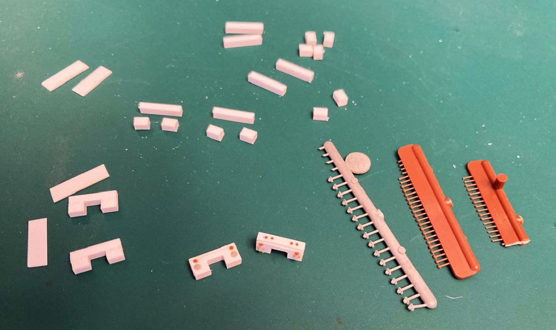
As the 1902 flat cars and coal cars left the C&S shops at the same time, I'm assuming that the end beam details are identical. The draft gear striker plate looks taller here, with the truss rod NBW below the bolt head securing the striker plate to block. As I'm still working on several of Bill's C&S boxcar kits, I have already worked out construction of the striker block in styrene, and have a large stash of precut parts:
The blocks are 3 pieces of 0.080" thick styrene glued together, then sanded flush at the ends. A piece of 0.010' x 0.156" styrene is then glued over the front of the block to represent the striker plate, the opening cut out with a sharp knife, and squared up with needle files. The truss rod NBW is Grandt #93, while Tichy rivets were used--0.030" for the striker plate, 0.025" for the four bolt heads atop the block. Before attaching the blocks to the end beams, I located and drilled out a vertical 0.020" hole for the brake staff in one of them--it is much easier to do this now than after the part is attached to the car.
Finally, the striker blocks were attached to the end beams, making sure that the one with the vertical hole was glued to the "B" end of the car:
Whew! Such a long post, hope ya'll find this helpful.
In the next week or so, I will finish building up the other three kits to this level of construction, so I can stain all the decks at the same time. Then, moving on with underframe detailing (plumbing / brake rigging and such) and finally the open box body and side stakes.
Jim Courtney
Poulsbo, WA
Poulsbo, WA
| Free forum by Nabble | Edit this page |