Flanger Operation
Posted by Keith Hayes on Jun 09, 2024; 12:02am
URL: http://c-sng-discussion-forum.254.s1.nabble.com/Flanger-015-tp19711p19787.html
Espee, you are correct on all points.
The issue I have been struggling with is the flanger mechanism. All the photos seem to hide a key part, but Jerry's drawing is a huge help. I have marked it up in the hopes to demystify the works.
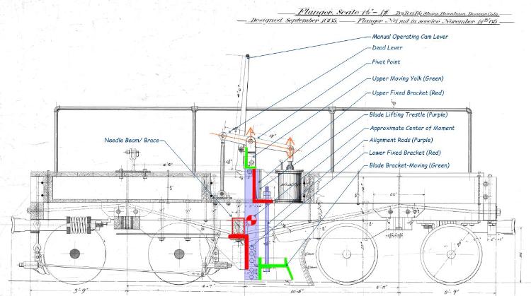
The fixed parts are in red, the moving parts are green and the purple are the alignment rods and (for lack of a better phrase) "trestle" the blade moves up and down on.
As Mike and I corresponded behind the scenes, I figured that flangers had to have some sort of truss rod to hold the works together, and indeed they do! There is a needle beam just aft of the center of the car. Two truss rods run from the coupler pockets under the needle beam to lock the car together. Further, there are two more rods that extend from the draft gear to the lower fixed bracket to help resist the rearward force the blade places on this bracket when plowing. In structures, we call this a rotational moment: in the diagram, the force of plowing induces a clockwise motion on the lower bracket. This force is resisted by the two rods, the needle beam and the frame of the car.
The blade also places a force on the trestle, which in turn bears on the rear-facing face of the upper fixed bracket. Using high-order computation (my eyeballs), the center of the moment seems like it is about at the bottom of the beam. This in turn induces a force on the top of the car sills and downward on the front truck.
The air cylinder moves the live end of the lever up to raise (and lower) the blade. There is also a manual handle and the sides are in the form of a cam to provide a touch of leverage in the case Jumbo was not assigned to the crew. The manual lever can me secured in the raised position with the bracket above the rear truck.
I recall reading that Al Pearlman directed D&RGW NG maintenance crews to stop using rail-based MOW equipment like flangers and spreaders. Caterpillar tractors created much more wear on the track and were less efficient. I heard when Spreader OU was resuscitated about a decade back, the crews really enjoyed working with it because all the forces...just worked. The car was heavy (OU is all-steel), the blades are symmetric about the track center line, and it was designed to move snow and rock. The C&TS crews were able to get a lot of work done in a short period of time, and I remember the ROW profile looked amazing!
I suspect flangers are similar to operate as OU. Jerry Day's video of the D&S flangers make it look pretty easy. The axial loads extend through the drawbars, and the center of the moment seems reasonably low. You can bet that they could be fussy, though as all the forces are kept on the tracks by the weight and some pretty small flanges. These cars weigh 22,000 pounds wet--the space under the platform and between the upper beams was packed with scrap. I will put in a couple brass bars and leave a board off to show some tie plates, spikes and fishplates. As the photos indicate, mishaps were common, and the D&RGW learned from this and rebuilt them with steel frames. The truss rods seemed to remain in place, but they just got welded to the steel and don't seem to extend to the draft gear plates at the car ends--at least on OC.
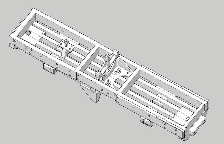
Progress on the revised frame is purring along. I have one last piece to model, the blade bracket. I will create this as a separate part, and fabricate the blades out of brass and styrene. It just seems easier that way. As the first print turned out pretty well, I modeled most of the square carriage bolt nuts, so now I don't have to drill those out. Same for some of the bolster end detail, and some nice metal straps. The air piping, handrails and signal mechanism will all be fabricated from brass. If the car works out in S, I will post it on Shapeways in S and O for others to purchase. I am not going to guarantee this is the most accurate model, but it may be faster than doing it yourself if you just have to have one of these.
Sound like the origin story is still up for debate. The D&RG, RGS and C&S cars bear remarkable similarities, though photos of key parts are limited. Even if they are not the same, they are pretty close, with the exception of RGS 01 having a much longer frame with the blade set forward on the car. I will let a physics specialist school us on the forces, but that doesn't seem like the right move, unless they had a large load on the rear truck. In S, this is a tiny little model, about 3" long.
URL: http://c-sng-discussion-forum.254.s1.nabble.com/Flanger-015-tp19711p19787.html
Espee, you are correct on all points.
The issue I have been struggling with is the flanger mechanism. All the photos seem to hide a key part, but Jerry's drawing is a huge help. I have marked it up in the hopes to demystify the works.
The fixed parts are in red, the moving parts are green and the purple are the alignment rods and (for lack of a better phrase) "trestle" the blade moves up and down on.
As Mike and I corresponded behind the scenes, I figured that flangers had to have some sort of truss rod to hold the works together, and indeed they do! There is a needle beam just aft of the center of the car. Two truss rods run from the coupler pockets under the needle beam to lock the car together. Further, there are two more rods that extend from the draft gear to the lower fixed bracket to help resist the rearward force the blade places on this bracket when plowing. In structures, we call this a rotational moment: in the diagram, the force of plowing induces a clockwise motion on the lower bracket. This force is resisted by the two rods, the needle beam and the frame of the car.
The blade also places a force on the trestle, which in turn bears on the rear-facing face of the upper fixed bracket. Using high-order computation (my eyeballs), the center of the moment seems like it is about at the bottom of the beam. This in turn induces a force on the top of the car sills and downward on the front truck.
The air cylinder moves the live end of the lever up to raise (and lower) the blade. There is also a manual handle and the sides are in the form of a cam to provide a touch of leverage in the case Jumbo was not assigned to the crew. The manual lever can me secured in the raised position with the bracket above the rear truck.
I recall reading that Al Pearlman directed D&RGW NG maintenance crews to stop using rail-based MOW equipment like flangers and spreaders. Caterpillar tractors created much more wear on the track and were less efficient. I heard when Spreader OU was resuscitated about a decade back, the crews really enjoyed working with it because all the forces...just worked. The car was heavy (OU is all-steel), the blades are symmetric about the track center line, and it was designed to move snow and rock. The C&TS crews were able to get a lot of work done in a short period of time, and I remember the ROW profile looked amazing!
I suspect flangers are similar to operate as OU. Jerry Day's video of the D&S flangers make it look pretty easy. The axial loads extend through the drawbars, and the center of the moment seems reasonably low. You can bet that they could be fussy, though as all the forces are kept on the tracks by the weight and some pretty small flanges. These cars weigh 22,000 pounds wet--the space under the platform and between the upper beams was packed with scrap. I will put in a couple brass bars and leave a board off to show some tie plates, spikes and fishplates. As the photos indicate, mishaps were common, and the D&RGW learned from this and rebuilt them with steel frames. The truss rods seemed to remain in place, but they just got welded to the steel and don't seem to extend to the draft gear plates at the car ends--at least on OC.
Progress on the revised frame is purring along. I have one last piece to model, the blade bracket. I will create this as a separate part, and fabricate the blades out of brass and styrene. It just seems easier that way. As the first print turned out pretty well, I modeled most of the square carriage bolt nuts, so now I don't have to drill those out. Same for some of the bolster end detail, and some nice metal straps. The air piping, handrails and signal mechanism will all be fabricated from brass. If the car works out in S, I will post it on Shapeways in S and O for others to purchase. I am not going to guarantee this is the most accurate model, but it may be faster than doing it yourself if you just have to have one of these.
Sound like the origin story is still up for debate. The D&RG, RGS and C&S cars bear remarkable similarities, though photos of key parts are limited. Even if they are not the same, they are pretty close, with the exception of RGS 01 having a much longer frame with the blade set forward on the car. I will let a physics specialist school us on the forces, but that doesn't seem like the right move, unless they had a large load on the rear truck. In S, this is a tiny little model, about 3" long.
Keith Hayes
Leadville in Sn3
Leadville in Sn3
| Free forum by Nabble | Edit this page |