Flanger 015
Posted by Keith Hayes on May 24, 2024; 3:40pm
URL: http://c-sng-discussion-forum.254.s1.nabble.com/Flanger-015-tp19711.html
I have embarked on a build of a C&S flanger. There is not much information to base this on, but there is enough. I started with the folio that Jim kindly posted:

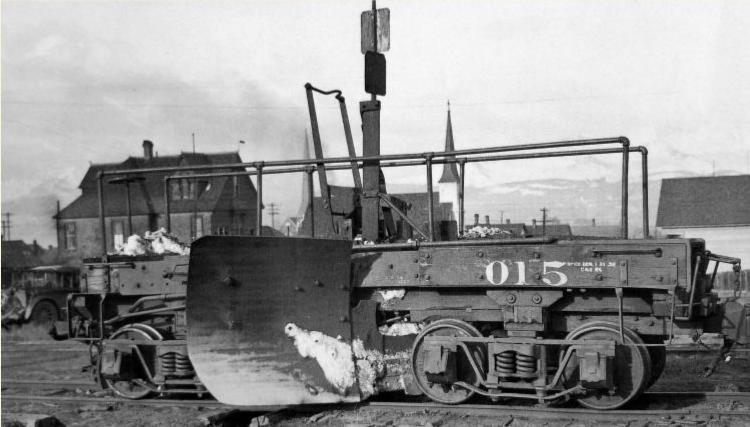
This provides the basic dimensions. Next, there is this very good side view taken in Leadville:
And a couple good end views taken earlier in the century:
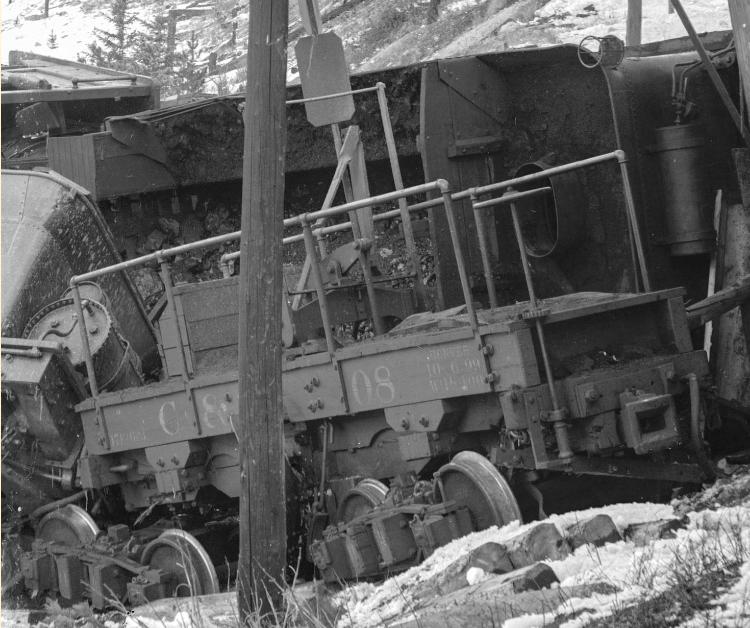
and
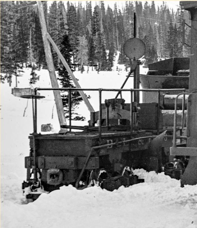
I think this last view may be a detail from a larger image taken at Hancock?
Mike Trent has constructed several fine models in On3, and he has been generous with his information and some photos:

Mike believes that the same company designed/ provided parts/ built RGS 01 and the three C&S flangers. The chief difference being that the C&S cars are shorter and symmetrical about the flanger mechanism well.
My plan is to create a 3d print of the frame, apply stained wood for the deck and supplement the 3d part with lots of NBWs and rivets. Mike used a Durango Press/ Weissman RGS 01 kit as a parts source for his model. I have located a Rio Grande Models D&RGW flanger kit to raid for my flanger mechanism.
I have a PBL brass model of D&RGW OE that I am consulting with a wary eye. The chief difference is that the C&S/RGS flangers are entirely constructed of wood with steel hardware. The D&RGW model has steel channel end beams and some other key steel parts. Noone seems to take the time to stick their camera down into the flanger mechanism to see how it ticks. I will consult Jerry Day's books. Once in Chama, the Friends were re-decking the two flangers there, and I learned that the space under the deck and above the lower sills was figured with every spare chunk of scrap iron the carmen could find in the shop. My plan is to include some brass barstock and leave one plank off to show some tie plates, a brake shoe, some spikes and some pig iron.
After three nights of SketchUp, here is what the frame looks like.

From the perspective of the side view
I still need to complete the bolster area and add the coupler pockets.
Anyone have ideas for elbows and pipe 'T's' for the handrails? Ideally brass.
Another project taking place is a quick build of a 9th Phase I coal.

The AP jury felt my use of BLW/ PVC underframe parts did not make the project a scratch-build. So I am 3d printing the part instead. Whateverl
While we are talking about 3d printing, I want to extend the invitation to Mr. Student to post some of his investigations in the area regarding a certain stock car model, among other things he is concocting in his evil basement laboratory. Bwa Ha Ha Ha HAAAAAA!
Feedback and more information on the flanger is welcome!
URL: http://c-sng-discussion-forum.254.s1.nabble.com/Flanger-015-tp19711.html
I have embarked on a build of a C&S flanger. There is not much information to base this on, but there is enough. I started with the folio that Jim kindly posted:
This provides the basic dimensions. Next, there is this very good side view taken in Leadville:
And a couple good end views taken earlier in the century:
and
I think this last view may be a detail from a larger image taken at Hancock?
Mike Trent has constructed several fine models in On3, and he has been generous with his information and some photos:
Mike believes that the same company designed/ provided parts/ built RGS 01 and the three C&S flangers. The chief difference being that the C&S cars are shorter and symmetrical about the flanger mechanism well.
My plan is to create a 3d print of the frame, apply stained wood for the deck and supplement the 3d part with lots of NBWs and rivets. Mike used a Durango Press/ Weissman RGS 01 kit as a parts source for his model. I have located a Rio Grande Models D&RGW flanger kit to raid for my flanger mechanism.
I have a PBL brass model of D&RGW OE that I am consulting with a wary eye. The chief difference is that the C&S/RGS flangers are entirely constructed of wood with steel hardware. The D&RGW model has steel channel end beams and some other key steel parts. Noone seems to take the time to stick their camera down into the flanger mechanism to see how it ticks. I will consult Jerry Day's books. Once in Chama, the Friends were re-decking the two flangers there, and I learned that the space under the deck and above the lower sills was figured with every spare chunk of scrap iron the carmen could find in the shop. My plan is to include some brass barstock and leave one plank off to show some tie plates, a brake shoe, some spikes and some pig iron.
After three nights of SketchUp, here is what the frame looks like.
From the perspective of the side view
I still need to complete the bolster area and add the coupler pockets.
Anyone have ideas for elbows and pipe 'T's' for the handrails? Ideally brass.
Another project taking place is a quick build of a 9th Phase I coal.
The AP jury felt my use of BLW/ PVC underframe parts did not make the project a scratch-build. So I am 3d printing the part instead. Whateverl
While we are talking about 3d printing, I want to extend the invitation to Mr. Student to post some of his investigations in the area regarding a certain stock car model, among other things he is concocting in his evil basement laboratory. Bwa Ha Ha Ha HAAAAAA!
Feedback and more information on the flanger is welcome!
Keith Hayes
Leadville in Sn3
Leadville in Sn3
| Free forum by Nabble | Edit this page |