Re: Leadville Designs Baggage/Express 1 in C&Sn3
Posted by Jim Courtney on Dec 20, 2023; 6:29am
URL: http://c-sng-discussion-forum.254.s1.nabble.com/Leadville-Designs-Baggage-Express-1-in-C-Sn3-tp19129p19288.html
Despite decorating and shopping for Christmas, I found time to finish up construction of baggage car 1.
Completing the underframe detailing--the "fourth layer":
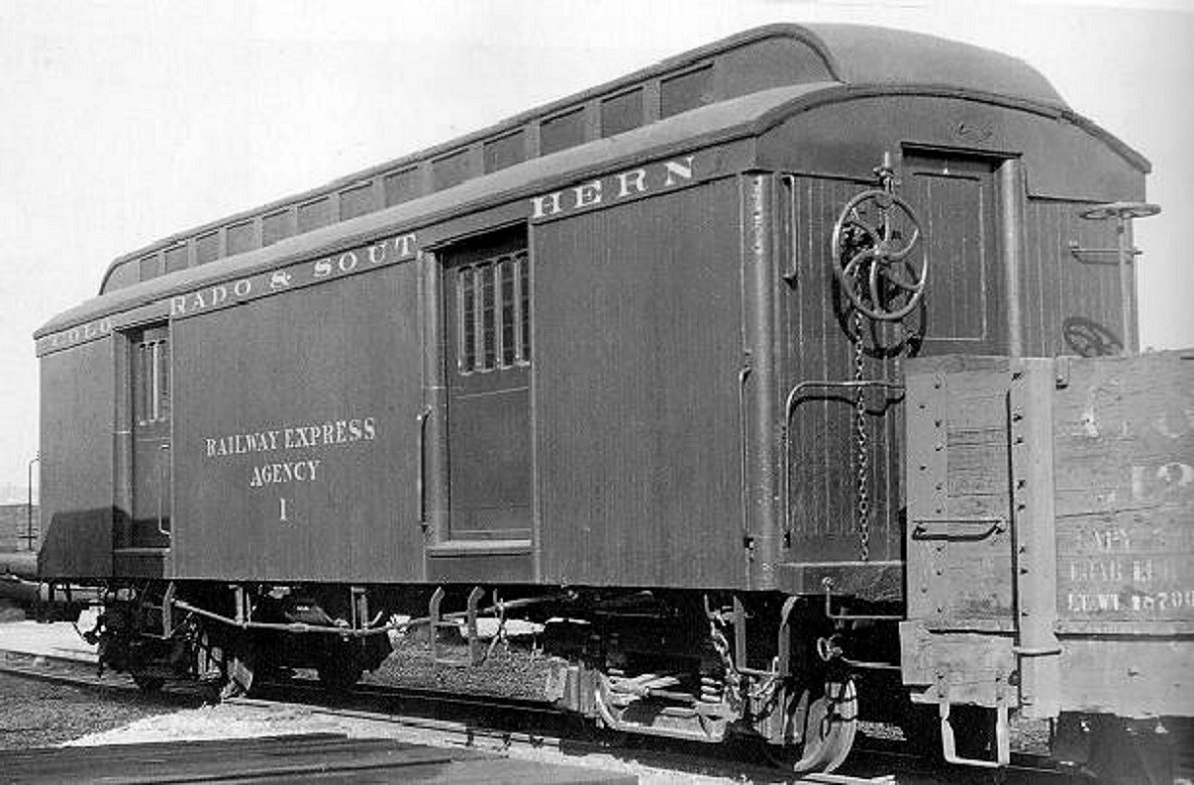
I used this 1922 Otto Perry photo as a reference for the underframe details:

Truss rods and "keepers":
The truss rods were formed by soldering 0.019" brass wire into each end of a PBL brass turnbuckle. Since I've another couple of cars that will use the same needle beam spacing, I constructed a bending jig. After the final bending and trimming, the truss rods were glued to the queen posts and to the floor at the inner edge of the bolster.
The "keepers" (my made-up word) were formed of 0.010" wire and installed. Their purpose seems to keep the truss rods up snug against the queen post end, and to keep them from moving laterally during a derailment. They were bolted to the floor at the inside edge of the needle beams:
Corner stirrups:
The etched strips in the kit fold up to match the corner stirrups in Ken Martin's plan exactly, 12" square in dimension. However . . . the corner stirrups in the photos are not square, rather they are taller rectangles. I formed mine to measure 12" x 15", in a folding jig, so they were all uniform. Before gluing to the floor and end beam, I drilled #80 holes in the little feet. After gluing in place, I drill through these holes into the resin end beam and the wood car floor, inserted small pieces of 0.012" wire and glued them in place with ACC. I hope this "pinning" will keep the stirrups from falling off, if bumped.
Baggage door side steps:
These are formed from a beautiful set of fold up etchings, the outer frame that curves outward from the underfloor mount (so as to be flush with the car side) and the middle step, with two small end folds to be attached to the inside of the frame. The outer frame protrudes down, 16 scale inches below the car floor. The instructions say to glue the middle step between the two sides of the outer frame. I pondered how I wanted to do this, as these steps protrude more and are more fragile than any other detail on the car bottom. The attachment needed to be:
a. Square relative to the sides of the frame.
b. Uniform for all four steps, the middle step 8 scale inches above the bottom.
c. Sturdy and permanent, so's not to ever have to repair a broken middle step after painting.
Since the pieces are 0.010' by 0.030" brass, I decided to solder them together and built a wood soldering jig to keep each piece aligned:
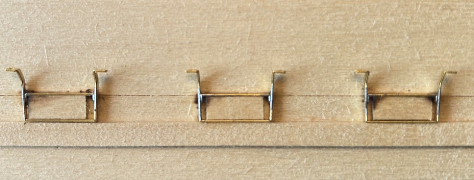
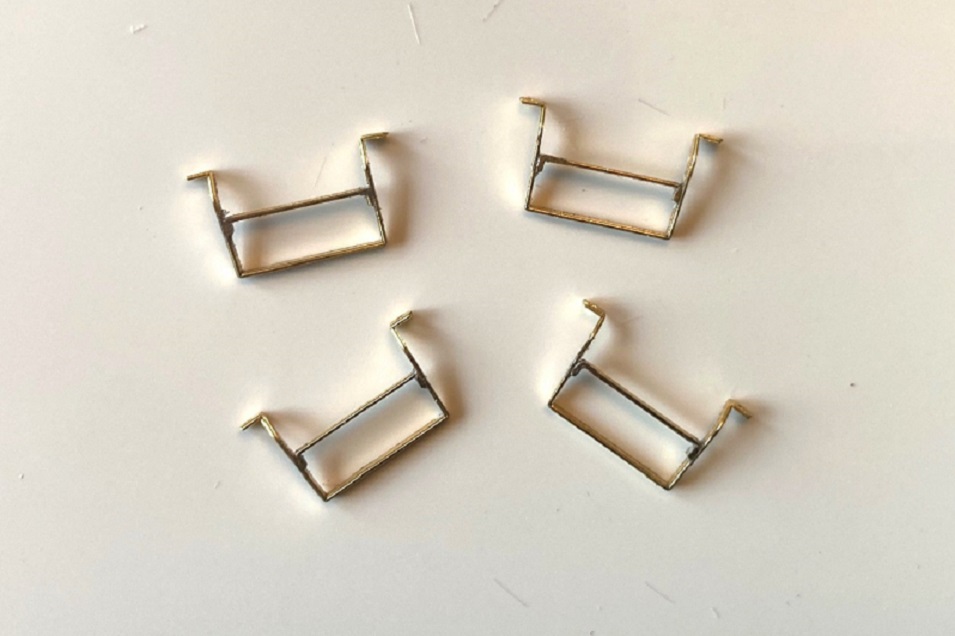
Short pieces of S scale 2x8 were glued to a small wood block as spacers, and the middle steps held in place with tweezers as a hot iron was applied to the fluxed joints, using a small dab of Carr's soldering paste. When the steps were carefully removed from the jig and cleaned up with a fiberglass eraser, they looked like this:
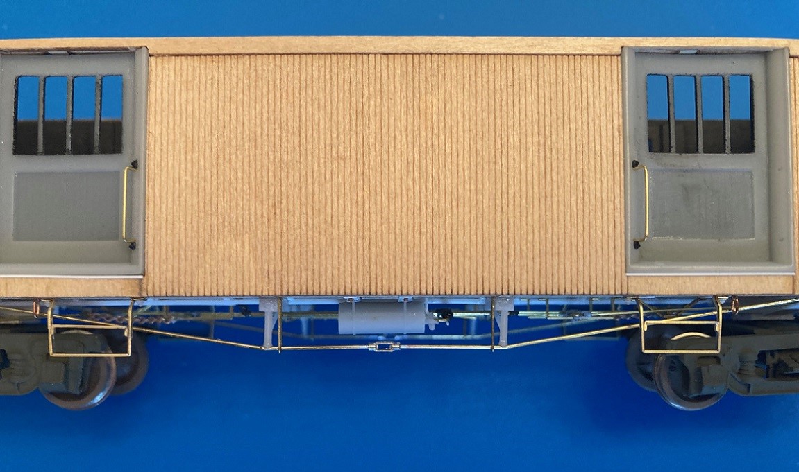
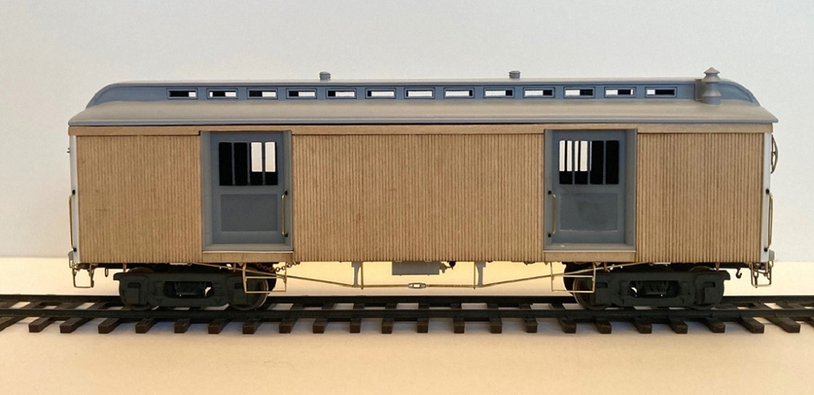
The floor has little marks for locating the steps, but are centered under each door. The Perry photo shows the steps to be offset, toward the center, under each door. The little mounting feet have a hole etched into them. When the steps had been located and glued to the floor with ACC, I drilled #75 through the holes, well into the wood floor. Grant #98 NBW with a long cut sprue were used to "pin" the steps, with MEK flowed into the wood to secure them in place. This is how they look on the car from the side:
The only other underframe detail is the rings for the attachment of the truck safety chains. Unlike other C&S passenger cars, these were ovoid in shape and were open to the ends rather than the sides, best seen in this photo:
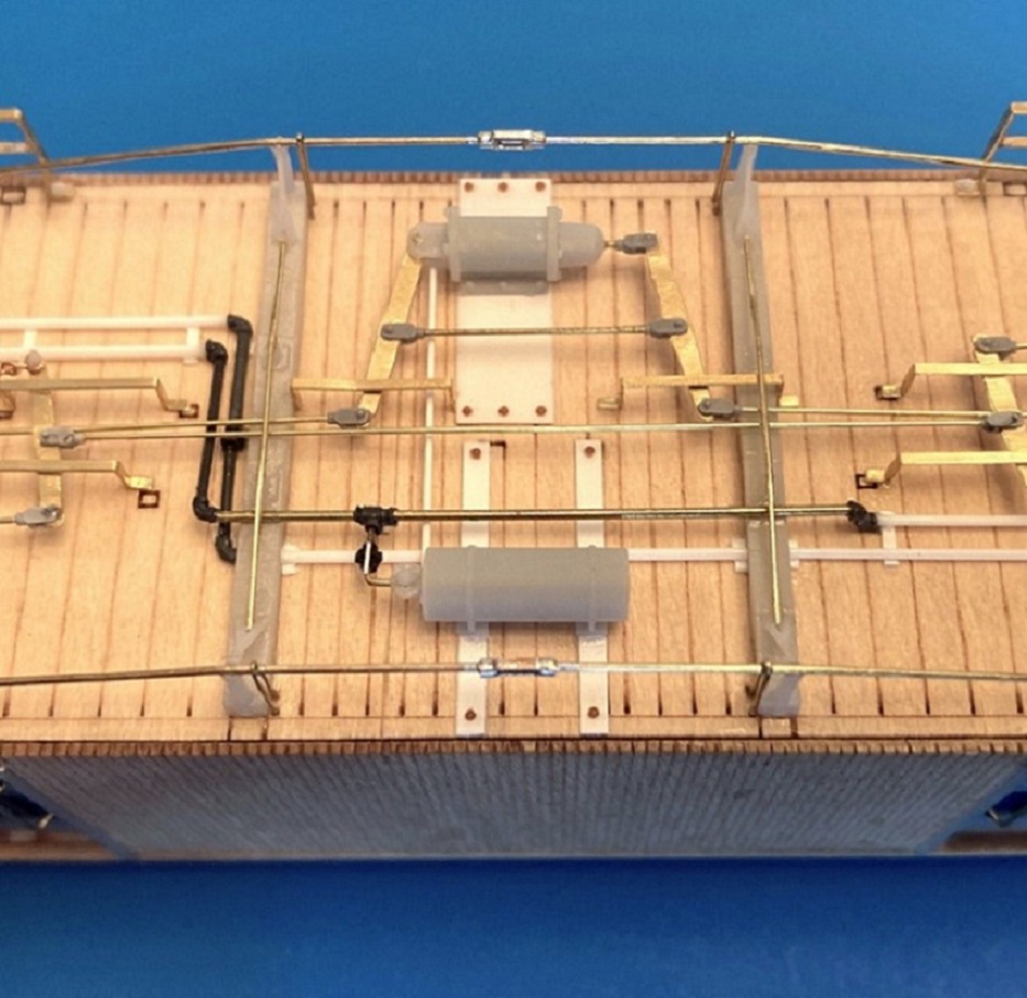
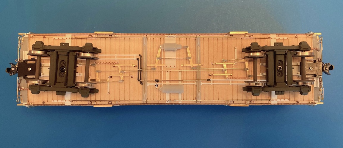
I fabricated these oblong rings of individual links of chain, using tiny etched brass eyelets to attach them to the floor, hoping they don't get bumped off. Here is the completed underframe:
Finishing the ends:
Not much left to do. I fabricated mounting fixtures for the brake and signal air hoses from styrene channel and mounted them just behind the end beam. Uncoupling rods, with their ringed ends, were formed from 0.015" wire, then mounted to the end beam with long stemmed eyelets. Finally, the big brake wheels were glued to the shafts.
As requested, here is the completed baggage car, waiting for primer and a color coat:
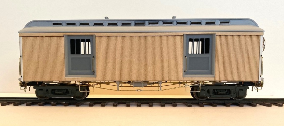
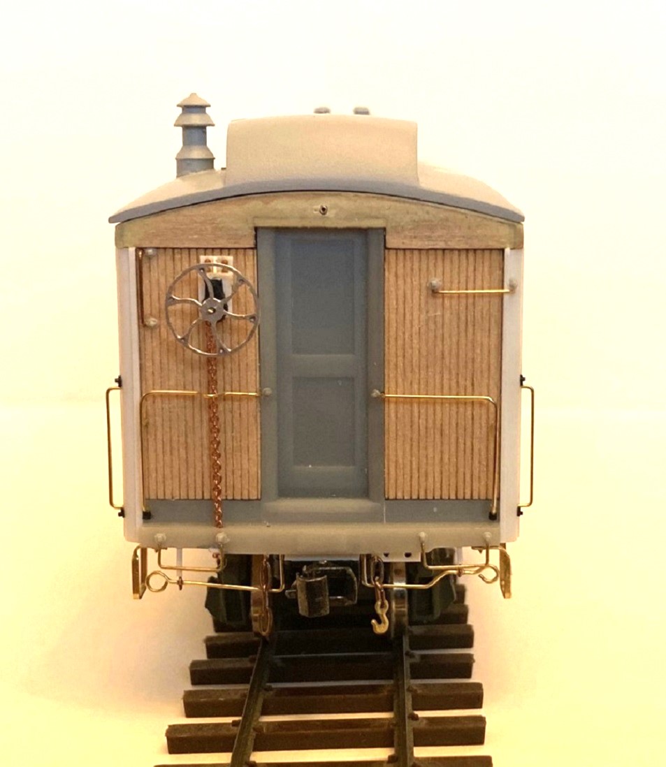
Hopefully, my next post will feature a green baggage car with gold lettering . . . there are still 12 days before the New Year.
URL: http://c-sng-discussion-forum.254.s1.nabble.com/Leadville-Designs-Baggage-Express-1-in-C-Sn3-tp19129p19288.html
Despite decorating and shopping for Christmas, I found time to finish up construction of baggage car 1.
Completing the underframe detailing--the "fourth layer":
I used this 1922 Otto Perry photo as a reference for the underframe details:
Truss rods and "keepers":
The truss rods were formed by soldering 0.019" brass wire into each end of a PBL brass turnbuckle. Since I've another couple of cars that will use the same needle beam spacing, I constructed a bending jig. After the final bending and trimming, the truss rods were glued to the queen posts and to the floor at the inner edge of the bolster.
The "keepers" (my made-up word) were formed of 0.010" wire and installed. Their purpose seems to keep the truss rods up snug against the queen post end, and to keep them from moving laterally during a derailment. They were bolted to the floor at the inside edge of the needle beams:
Corner stirrups:
The etched strips in the kit fold up to match the corner stirrups in Ken Martin's plan exactly, 12" square in dimension. However . . . the corner stirrups in the photos are not square, rather they are taller rectangles. I formed mine to measure 12" x 15", in a folding jig, so they were all uniform. Before gluing to the floor and end beam, I drilled #80 holes in the little feet. After gluing in place, I drill through these holes into the resin end beam and the wood car floor, inserted small pieces of 0.012" wire and glued them in place with ACC. I hope this "pinning" will keep the stirrups from falling off, if bumped.
Baggage door side steps:
These are formed from a beautiful set of fold up etchings, the outer frame that curves outward from the underfloor mount (so as to be flush with the car side) and the middle step, with two small end folds to be attached to the inside of the frame. The outer frame protrudes down, 16 scale inches below the car floor. The instructions say to glue the middle step between the two sides of the outer frame. I pondered how I wanted to do this, as these steps protrude more and are more fragile than any other detail on the car bottom. The attachment needed to be:
a. Square relative to the sides of the frame.
b. Uniform for all four steps, the middle step 8 scale inches above the bottom.
c. Sturdy and permanent, so's not to ever have to repair a broken middle step after painting.
Since the pieces are 0.010' by 0.030" brass, I decided to solder them together and built a wood soldering jig to keep each piece aligned:
Short pieces of S scale 2x8 were glued to a small wood block as spacers, and the middle steps held in place with tweezers as a hot iron was applied to the fluxed joints, using a small dab of Carr's soldering paste. When the steps were carefully removed from the jig and cleaned up with a fiberglass eraser, they looked like this:
The floor has little marks for locating the steps, but are centered under each door. The Perry photo shows the steps to be offset, toward the center, under each door. The little mounting feet have a hole etched into them. When the steps had been located and glued to the floor with ACC, I drilled #75 through the holes, well into the wood floor. Grant #98 NBW with a long cut sprue were used to "pin" the steps, with MEK flowed into the wood to secure them in place. This is how they look on the car from the side:
The only other underframe detail is the rings for the attachment of the truck safety chains. Unlike other C&S passenger cars, these were ovoid in shape and were open to the ends rather than the sides, best seen in this photo:
I fabricated these oblong rings of individual links of chain, using tiny etched brass eyelets to attach them to the floor, hoping they don't get bumped off. Here is the completed underframe:
Finishing the ends:
Not much left to do. I fabricated mounting fixtures for the brake and signal air hoses from styrene channel and mounted them just behind the end beam. Uncoupling rods, with their ringed ends, were formed from 0.015" wire, then mounted to the end beam with long stemmed eyelets. Finally, the big brake wheels were glued to the shafts.
As requested, here is the completed baggage car, waiting for primer and a color coat:
Hopefully, my next post will feature a green baggage car with gold lettering . . . there are still 12 days before the New Year.
Jim Courtney
Poulsbo, WA
Poulsbo, WA
| Free forum by Nabble | Edit this page |