Re: Leadville Designs Baggage/Express 1 in C&Sn3
Posted by Jim Courtney on Dec 03, 2023; 7:56am
URL: http://c-sng-discussion-forum.254.s1.nabble.com/Leadville-Designs-Baggage-Express-1-in-C-Sn3-tp19129p19237.html
I trust all had a good Thanksgiving! But frankly, all the shopping, food preparation, entertaining guests, clean-up and the persisting drowsiness of eating leftover turkey has greatly interrupted this project. But I caught up some this week.
Underside Detailing:
C&S passenger cars, by their nature, rode very high above the rail, making all that brake rigging and stuff very visible. I really, really like Bill's detailing parts for the underframe, both printed resin parts and brass etchings. These are standard Bill Meredith parts, supplied with all his passenger car kits. My described buildup applies to all C&S passenger cars, with minor variations in placement.
Having used Bill's parts to build out Roy's RPO/Coach, I learned after the fact that the underside detailing goes better by applying the parts in "layers", the parts directly contacting the floor first, followed by layers of parts as one build downward (or is it up??)
The first layer of parts are the mounting straps for the reservoir, cylinder and the truck brake lever fulcrums. These are supplied as brass etchings in the kit. I chose to substitute 0.010" Evergreen styrene strips, widths to match the etched parts, cut to length per the etched ones. With the floor coated with Dullcote, I could use MEK to attach the parts, and move them a bit 'til all was square and straight. Tichy 0.020 and 0.025 rivets were used for detail. The engraved lines for the reservoir mounting straps are too close together--use the reservoir print to locate them.
Next the needle beams, with the tall, braced queen posts--the needle beam itself is trussed, there are two tiny queen posts printed in the mid portion of the needle beam. The truss rod is formed of 0.015" wire and glued to these little guys, and into the crotch of the main queen post brace. Since I will use this part for 7-8 other passenger car projects, I went to the trouble of making a bending jig. The bottom of the needle beam is 0.040" above the top of the truss rod (see below).
I have no idea whether the trainline air piping is accurate for baggage car C&S 1. I merely copied the arrangement as on my Overland brass coaches. The "piping" is Evergreen 0.025" rod, with Grandt O scale plumbing fixtures (elbows, tees, unions and such).
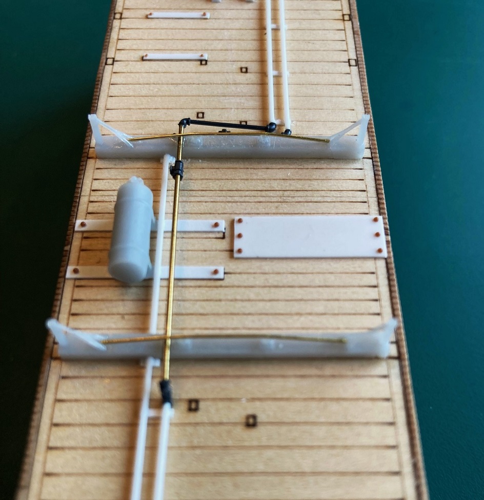
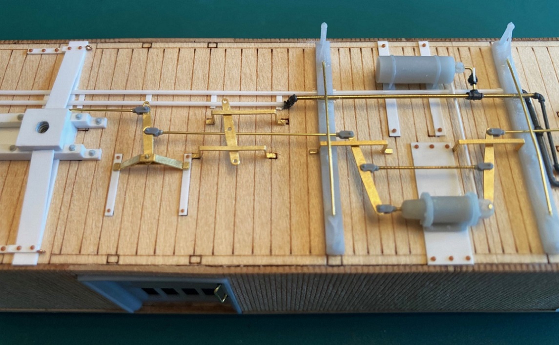
The reservoir's triple-valve was drilled 0.015" for a future branch trainline, then glued to its mounting straps. The air signal line is the outer pipe, is modeled passing thru the needle beams. The air brake trainline is the inner piping, it angles down and is attached to the underside of the needle beams. Small lengths of 0.010 x0.030 styrene were cut to length as supports for the two pipes. Here's how the first layer of detailing looks at this point:
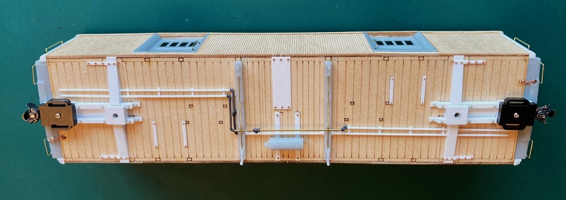
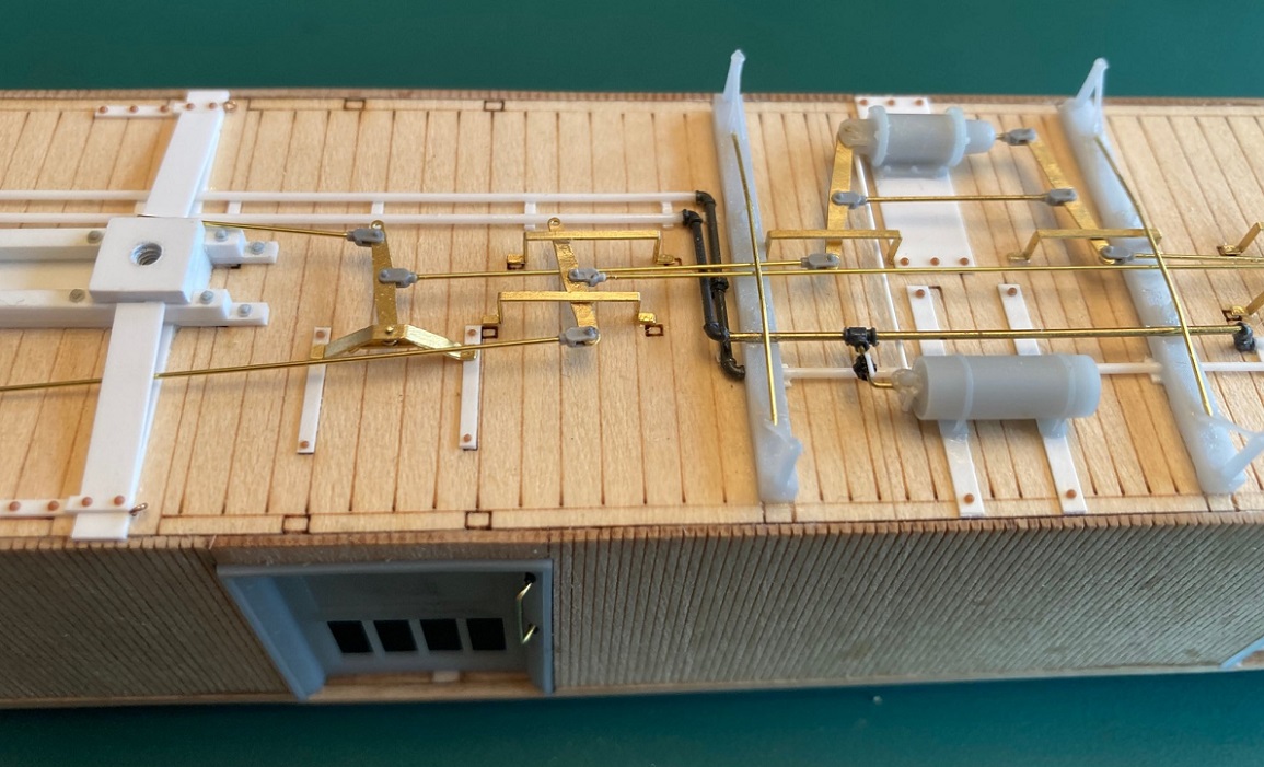
The second layer of detailing is the air brake cylinder, main brake levers, truck lever/fulcrums, connecting rods and clevises. The build up of the RPO/coach impressed me that the cylinder with its brake levers, tie rod and clevises should be built up first and installed as a subassembly. All clevises are PBL parts, to my eye, more in scale than Bill's etched clevises--your choice. All brake rods are 0.015" brass wire. Here is the brake cylinder assembly installed:
Note that there are three slightly different sizes of etched levers, these are the longest. The free end of the levers should end up at the center line of the car. Note that the branch trainline, with cutoff valve have been installed to the reservoir.
Moving toward the bolsters, the fulcrums/levers for the truck brake lever must be built up from 4 parts:
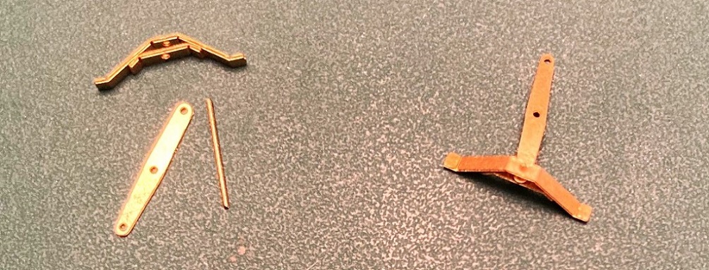
The fulcrum pieces have fold lines and a hole etched in the center. This can be confusing, as there are three pairs of such parts. The longest and shortest are for the fulcrums. The middle length ones are lower brake staff mounts for the end beams of coach platforms, not used in this model. I saved mine for use on Roy's combine 20/025. The larger piece is folded to shape, its little feet folded flat. The width of the fulcrum is determined by the distance between the two mounting straps. The shorter piece is then glued inside the fulcrum with the truck lever (the shortest of the the lever lengths) glued into the slot and all three pieces held together with a short length of wire.
Here is how the assembled fulcrum/lever assembly looks glued to the mounting straps, the center hole of the lever at the car centerline:

Note that the brake rod with clevis has been added to stabilize the assembly. Also note that the clevis is inboard of the small hole at the end of the brake lever. We will see the importance of that location below. Next, the truck levers are connected to the main brake levers, with rods and clevises:

There are 6 etched strips with fold lines for the brake lever safety rails. I formed up two for the main brake levers, one would not fit between the cylinder support strip and the needle beam and had to have its little feet amputated. Before installing the two safety rails, the crossover pipe from reservoir triple valve and cylinder was installed ( length of 0.015" styrene rod). Here's how things look after installing all the air brake levers of the "second layer":
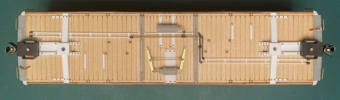
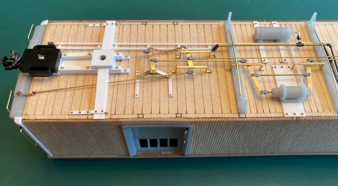
The "third layer" consists of the hand brake levers, rods and clevises. First, the remaining 4 safety rails were formed up and applied to the floor. Bill has engraved little foot prints for their locations. I was only then that I noticed that the two ends were not symmetric with these little marks. I carefully glued the rails in place, trying to keep them all the same distance from the side of the car body. When dry, the hand brake levers were carefully inserted beneath the safety rails and on top of the air brake truck lever rods. I positioned them so that they were parallel to the truck brake levers, then carefully glued them into place:
Next, the tie rod and clevises were installed between the two hand brake levers. Hand brake connecting rods with clevises were then attached to hand brake levers so that the rods passed through the bolsters and glued near the loops where the end brake chains were secured:
To complete this "third layer", the two brake lever systems have to be connected with lengths of chain between the the holes of the air brake lever and the hand brake lever. I measure the distance, added two links of chain for slack. On the RPO/Coach build, I actually tried to open the end links of chain to attach it to the holes of the levers. After two attempts I realized this was ridiculous--watch making not model building. Instead I used Grand #63 NBWs, cut from the sprue with long stems. I passed the stem first through the chain, then through the holes in the levers, and ACC 's them in place, trimming off the excess stem when dry:
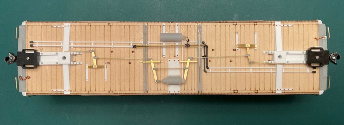
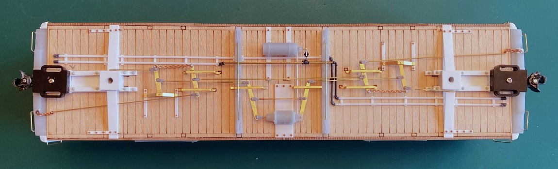
So here's how things look with the first three layers of details applied:
I'm hoping to finish up the roof tomorrow. This next week, I'll try to add the next layer of details to the underside: Truss rods, truss rod "keepers", baggage door steps and corner steps.
And it's about time to put up the Christmas Tree . . .
URL: http://c-sng-discussion-forum.254.s1.nabble.com/Leadville-Designs-Baggage-Express-1-in-C-Sn3-tp19129p19237.html
I trust all had a good Thanksgiving! But frankly, all the shopping, food preparation, entertaining guests, clean-up and the persisting drowsiness of eating leftover turkey has greatly interrupted this project. But I caught up some this week.
Underside Detailing:
C&S passenger cars, by their nature, rode very high above the rail, making all that brake rigging and stuff very visible. I really, really like Bill's detailing parts for the underframe, both printed resin parts and brass etchings. These are standard Bill Meredith parts, supplied with all his passenger car kits. My described buildup applies to all C&S passenger cars, with minor variations in placement.
Having used Bill's parts to build out Roy's RPO/Coach, I learned after the fact that the underside detailing goes better by applying the parts in "layers", the parts directly contacting the floor first, followed by layers of parts as one build downward (or is it up??)
The first layer of parts are the mounting straps for the reservoir, cylinder and the truck brake lever fulcrums. These are supplied as brass etchings in the kit. I chose to substitute 0.010" Evergreen styrene strips, widths to match the etched parts, cut to length per the etched ones. With the floor coated with Dullcote, I could use MEK to attach the parts, and move them a bit 'til all was square and straight. Tichy 0.020 and 0.025 rivets were used for detail. The engraved lines for the reservoir mounting straps are too close together--use the reservoir print to locate them.
Next the needle beams, with the tall, braced queen posts--the needle beam itself is trussed, there are two tiny queen posts printed in the mid portion of the needle beam. The truss rod is formed of 0.015" wire and glued to these little guys, and into the crotch of the main queen post brace. Since I will use this part for 7-8 other passenger car projects, I went to the trouble of making a bending jig. The bottom of the needle beam is 0.040" above the top of the truss rod (see below).
I have no idea whether the trainline air piping is accurate for baggage car C&S 1. I merely copied the arrangement as on my Overland brass coaches. The "piping" is Evergreen 0.025" rod, with Grandt O scale plumbing fixtures (elbows, tees, unions and such).
The reservoir's triple-valve was drilled 0.015" for a future branch trainline, then glued to its mounting straps. The air signal line is the outer pipe, is modeled passing thru the needle beams. The air brake trainline is the inner piping, it angles down and is attached to the underside of the needle beams. Small lengths of 0.010 x0.030 styrene were cut to length as supports for the two pipes. Here's how the first layer of detailing looks at this point:
The second layer of detailing is the air brake cylinder, main brake levers, truck lever/fulcrums, connecting rods and clevises. The build up of the RPO/coach impressed me that the cylinder with its brake levers, tie rod and clevises should be built up first and installed as a subassembly. All clevises are PBL parts, to my eye, more in scale than Bill's etched clevises--your choice. All brake rods are 0.015" brass wire. Here is the brake cylinder assembly installed:
Note that there are three slightly different sizes of etched levers, these are the longest. The free end of the levers should end up at the center line of the car. Note that the branch trainline, with cutoff valve have been installed to the reservoir.
Moving toward the bolsters, the fulcrums/levers for the truck brake lever must be built up from 4 parts:
The fulcrum pieces have fold lines and a hole etched in the center. This can be confusing, as there are three pairs of such parts. The longest and shortest are for the fulcrums. The middle length ones are lower brake staff mounts for the end beams of coach platforms, not used in this model. I saved mine for use on Roy's combine 20/025. The larger piece is folded to shape, its little feet folded flat. The width of the fulcrum is determined by the distance between the two mounting straps. The shorter piece is then glued inside the fulcrum with the truck lever (the shortest of the the lever lengths) glued into the slot and all three pieces held together with a short length of wire.
Here is how the assembled fulcrum/lever assembly looks glued to the mounting straps, the center hole of the lever at the car centerline:
Note that the brake rod with clevis has been added to stabilize the assembly. Also note that the clevis is inboard of the small hole at the end of the brake lever. We will see the importance of that location below. Next, the truck levers are connected to the main brake levers, with rods and clevises:
There are 6 etched strips with fold lines for the brake lever safety rails. I formed up two for the main brake levers, one would not fit between the cylinder support strip and the needle beam and had to have its little feet amputated. Before installing the two safety rails, the crossover pipe from reservoir triple valve and cylinder was installed ( length of 0.015" styrene rod). Here's how things look after installing all the air brake levers of the "second layer":
The "third layer" consists of the hand brake levers, rods and clevises. First, the remaining 4 safety rails were formed up and applied to the floor. Bill has engraved little foot prints for their locations. I was only then that I noticed that the two ends were not symmetric with these little marks. I carefully glued the rails in place, trying to keep them all the same distance from the side of the car body. When dry, the hand brake levers were carefully inserted beneath the safety rails and on top of the air brake truck lever rods. I positioned them so that they were parallel to the truck brake levers, then carefully glued them into place:
Next, the tie rod and clevises were installed between the two hand brake levers. Hand brake connecting rods with clevises were then attached to hand brake levers so that the rods passed through the bolsters and glued near the loops where the end brake chains were secured:
To complete this "third layer", the two brake lever systems have to be connected with lengths of chain between the the holes of the air brake lever and the hand brake lever. I measure the distance, added two links of chain for slack. On the RPO/Coach build, I actually tried to open the end links of chain to attach it to the holes of the levers. After two attempts I realized this was ridiculous--watch making not model building. Instead I used Grand #63 NBWs, cut from the sprue with long stems. I passed the stem first through the chain, then through the holes in the levers, and ACC 's them in place, trimming off the excess stem when dry:
So here's how things look with the first three layers of details applied:
I'm hoping to finish up the roof tomorrow. This next week, I'll try to add the next layer of details to the underside: Truss rods, truss rod "keepers", baggage door steps and corner steps.
And it's about time to put up the Christmas Tree . . .
Jim Courtney
Poulsbo, WA
Poulsbo, WA
| Free forum by Nabble | Edit this page |