Re: Leadville Designs Baggage/Express 1 in C&Sn3
Posted by Jim Courtney on Oct 09, 2023; 10:33pm
URL: http://c-sng-discussion-forum.254.s1.nabble.com/Leadville-Designs-Baggage-Express-1-in-C-Sn3-tp19129p19152.html
Okay, back to the C&S baggage car project -- some progress to report.
Before installing the ends, prep work for installation and future detailing was done:
The back surface of the printed end beams are not flat, rather have a wavy, irregular surface due to some artifact of resin printing (perhaps Steve Guty or Roy Stevens can 'splain it to us). Using a 6" pillar file the back of the lower print was filed flush with the back of the interior wall.
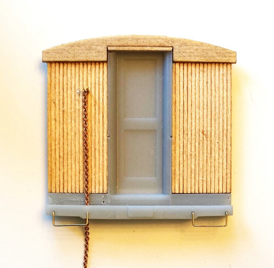
Flipping the ends over, holes for mounting the inverted L-shaped end grab irons were drilled (Bill printed dimples to mark the location, 2 on the vertical door frames, and two on the lower sheet metal below the door, near the edge of the ends).
The end beams have dimples for mounting two 17" drop grabs. These were drilled #80 and the drop grabs were formed and installed.
Using Ken Martin's plans and photos, the location of the horizontal brake staff, for the big brake wheels was located and drilled #76. Short pieces of 0.019 wire were installed as locators. Tiny lengths of 0.008 wire were installed just a smidge to the left of the brake staffs to hang the brake chain.
Lengths of chain were hung from the little wire vertically and the point that they touched the end beam was marked. The holes to allow the chain to pass through the end beams were drilled up from the bottom. starting with a 0.015" drill, gradually enlarging to a final drilling of 0.035", to clear the chain.
One end was the designated "B" end and a #80 hole was drilled for the retainer pipe.
These tasks will simplify adding details to the ends later:
The two ends were glued to the gluing blocks installed on the car body, lining up the bottom of the end fascia with the bottom of the side fascia. When everything looked vertical, I used ACC to secure the lower resin printed parts of the end. I ended up not using Bill's printed quarter round trim, as:
--Not all were straight.
--They are too long, need to be trimmed at the top to fit (the ends without grab iron dimples)
--I broke one in several places trying to get it off the stem to the print raft (correct terms, Steve?). Resin sometimes shatters when cut.
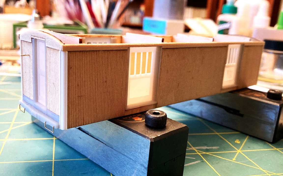
So, I made my own quarter round trim from Evergreen styrene 0.060" quarter-round, using HO scale 2x6 and 2x8s for the vertical straight trim. When cut and filed to length, they were glued into place at the corners with Gorilla ACC gel:
Now for the scary part, building the clerestory roof.
The roof framing consists of six laser cut profile ribs, an upper sub-roof and two notched side rails. Four of the ribs are glued to the underside of the top sub-roof, using a machinist square as the glue set. to make sure each is square. The little tabs at the top of the ribs protrude above the sub-roof a bit--don't sand this down, as they provide support for the gentile curving top roof panel later.
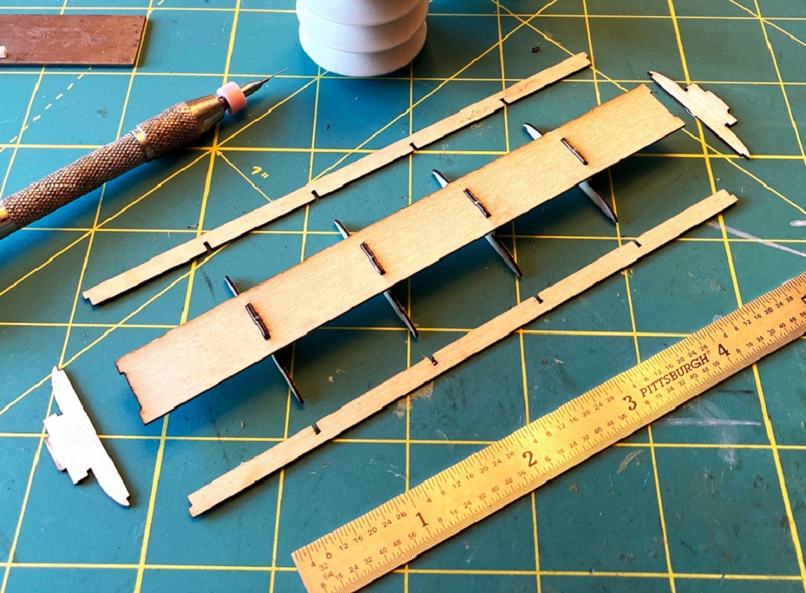
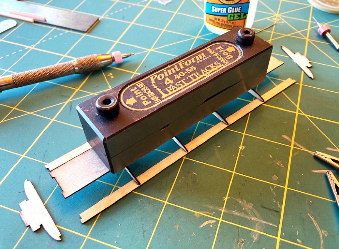
The two notched side rails were glued to the four ribs next, one at a time. The instructions say to use the included alligator clamps to clamp each joint, but I found that they distorted the joint. Instead, I used a weight from above:
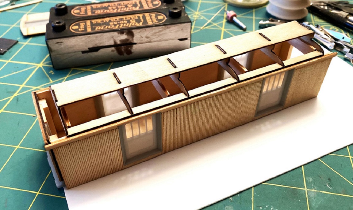
When the side rails were firmly dry at the joints, the two end profile ribs were added. This is how the clerestory roof framing looks atop the car body. The upper tabs on the car body joists keep the roof framing lined up and centered over the length of the car body:
Time now to add the lower clerestory roof panels. Examining the parts, I noticed some wood fuzz on the surface, Rather than sanding it and creating more fuzz, I removed the three roof panels from the fret, dressed the edges and gave the outer surfaces a couple of coats of Testors Dullcote from a rattle can to seal the grain (the underside of each piece, with the laser scribed bending lines were left raw wood for gluing. When dry, the tops of each panel were sanded until smooth.
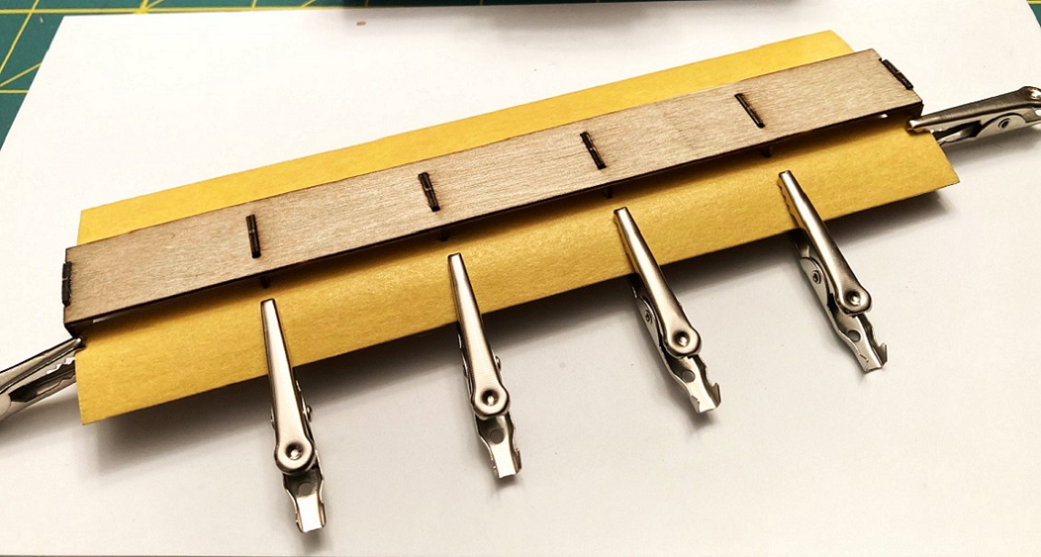
Before adding the lower roof panels to the frame, one at a time, the instruction advise covering each top surface with masking tape, just short of the little notches, presumably to keep them from getting marred by alligator teeth in the next clamping step. The notched edge of the side panel is inserted into the glue filled notch in the framing ribs (and a little glue on the ribs next to the notches and clamped into position until dry, repeating the process on the other side:
When this joint at the notched ribs is completely dry (overnight), liberal amounts of glue are applied to the remainder of each rib and the sides of the side rails, and clamped. I used the Micromark accordion glue applicator with the 20 gauge blunt needle to reach up under the roof panel to apply the glue to the ribs:
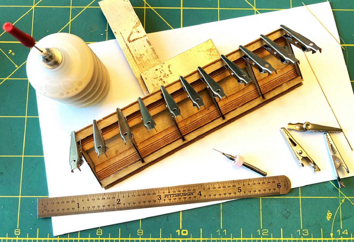
I have two kits, so I doubled up on the alligator clamps. Note that the lower roof panel rolls down past the bottom of the side rails, nearly an 1/8 inch--this will have to be sanded flush later. When the glued roof panel had dried overnight, I removed the clamps, and reinforced the joints with the roof ribs and side rails with a bead of thin ACC. The same process was used on the opposite lower roof panel, letting the glue dry overnight. Lots of glue drying going on here!
With the masking tape removed, this is how the clerestory framing with the lower roof panels installed looks:
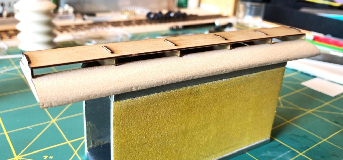
As there are visible alligator bite marks, the masking tape didn't seem to do its job--maybe two layers would work. Will have to fill these bite marks with putty, if still present after the next step.
Next up, I'll get a fresh piece of 800 grit sand paper, lay it flat on the hard, flat surface of the quartz kitchen counter tops and gently sand off the protruding roof edges back until they are flush with the bottom of the side rails and ribs; that is, the entire bottom of the roof assembly, so far, needs to be a perfectly flat plane,
We will see how this all turns out next time . . .
URL: http://c-sng-discussion-forum.254.s1.nabble.com/Leadville-Designs-Baggage-Express-1-in-C-Sn3-tp19129p19152.html
Okay, back to the C&S baggage car project -- some progress to report.
Before installing the ends, prep work for installation and future detailing was done:
The back surface of the printed end beams are not flat, rather have a wavy, irregular surface due to some artifact of resin printing (perhaps Steve Guty or Roy Stevens can 'splain it to us). Using a 6" pillar file the back of the lower print was filed flush with the back of the interior wall.
Flipping the ends over, holes for mounting the inverted L-shaped end grab irons were drilled (Bill printed dimples to mark the location, 2 on the vertical door frames, and two on the lower sheet metal below the door, near the edge of the ends).
The end beams have dimples for mounting two 17" drop grabs. These were drilled #80 and the drop grabs were formed and installed.
Using Ken Martin's plans and photos, the location of the horizontal brake staff, for the big brake wheels was located and drilled #76. Short pieces of 0.019 wire were installed as locators. Tiny lengths of 0.008 wire were installed just a smidge to the left of the brake staffs to hang the brake chain.
Lengths of chain were hung from the little wire vertically and the point that they touched the end beam was marked. The holes to allow the chain to pass through the end beams were drilled up from the bottom. starting with a 0.015" drill, gradually enlarging to a final drilling of 0.035", to clear the chain.
One end was the designated "B" end and a #80 hole was drilled for the retainer pipe.
These tasks will simplify adding details to the ends later:
The two ends were glued to the gluing blocks installed on the car body, lining up the bottom of the end fascia with the bottom of the side fascia. When everything looked vertical, I used ACC to secure the lower resin printed parts of the end. I ended up not using Bill's printed quarter round trim, as:
--Not all were straight.
--They are too long, need to be trimmed at the top to fit (the ends without grab iron dimples)
--I broke one in several places trying to get it off the stem to the print raft (correct terms, Steve?). Resin sometimes shatters when cut.
So, I made my own quarter round trim from Evergreen styrene 0.060" quarter-round, using HO scale 2x6 and 2x8s for the vertical straight trim. When cut and filed to length, they were glued into place at the corners with Gorilla ACC gel:
Now for the scary part, building the clerestory roof.
The roof framing consists of six laser cut profile ribs, an upper sub-roof and two notched side rails. Four of the ribs are glued to the underside of the top sub-roof, using a machinist square as the glue set. to make sure each is square. The little tabs at the top of the ribs protrude above the sub-roof a bit--don't sand this down, as they provide support for the gentile curving top roof panel later.
The two notched side rails were glued to the four ribs next, one at a time. The instructions say to use the included alligator clamps to clamp each joint, but I found that they distorted the joint. Instead, I used a weight from above:
When the side rails were firmly dry at the joints, the two end profile ribs were added. This is how the clerestory roof framing looks atop the car body. The upper tabs on the car body joists keep the roof framing lined up and centered over the length of the car body:
Time now to add the lower clerestory roof panels. Examining the parts, I noticed some wood fuzz on the surface, Rather than sanding it and creating more fuzz, I removed the three roof panels from the fret, dressed the edges and gave the outer surfaces a couple of coats of Testors Dullcote from a rattle can to seal the grain (the underside of each piece, with the laser scribed bending lines were left raw wood for gluing. When dry, the tops of each panel were sanded until smooth.
Before adding the lower roof panels to the frame, one at a time, the instruction advise covering each top surface with masking tape, just short of the little notches, presumably to keep them from getting marred by alligator teeth in the next clamping step. The notched edge of the side panel is inserted into the glue filled notch in the framing ribs (and a little glue on the ribs next to the notches and clamped into position until dry, repeating the process on the other side:
When this joint at the notched ribs is completely dry (overnight), liberal amounts of glue are applied to the remainder of each rib and the sides of the side rails, and clamped. I used the Micromark accordion glue applicator with the 20 gauge blunt needle to reach up under the roof panel to apply the glue to the ribs:
I have two kits, so I doubled up on the alligator clamps. Note that the lower roof panel rolls down past the bottom of the side rails, nearly an 1/8 inch--this will have to be sanded flush later. When the glued roof panel had dried overnight, I removed the clamps, and reinforced the joints with the roof ribs and side rails with a bead of thin ACC. The same process was used on the opposite lower roof panel, letting the glue dry overnight. Lots of glue drying going on here!
With the masking tape removed, this is how the clerestory framing with the lower roof panels installed looks:
As there are visible alligator bite marks, the masking tape didn't seem to do its job--maybe two layers would work. Will have to fill these bite marks with putty, if still present after the next step.
Next up, I'll get a fresh piece of 800 grit sand paper, lay it flat on the hard, flat surface of the quartz kitchen counter tops and gently sand off the protruding roof edges back until they are flush with the bottom of the side rails and ribs; that is, the entire bottom of the roof assembly, so far, needs to be a perfectly flat plane,
We will see how this all turns out next time . . .
Jim Courtney
Poulsbo, WA
Poulsbo, WA
| Free forum by Nabble | Edit this page |