Re: Type C/UP trucks
Posted by Jim Courtney on Jun 18, 2021; 6:34am
URL: http://c-sng-discussion-forum.254.s1.nabble.com/Type-C-UP-trucks-tp15497p16748.html
Michael, I do love these trucks, just what the doctor ordered! I've ordered two more prints of the current iteration to experiment with.
But they need to be durable to operate, and this iteration, even in S scale, is a bit too fragile. I snapped off another side frame trying to carefully remove a wheel set, so I could prime the truck. The weak point of the side frame are the three "bars" of the archbar, especially the top and bottom, where they attach to the side of the transom.
My suggestions:
1. Beef up the bars. Yours measure 0.012' thick by 0.050' wide. By comparison, Eric's RGM white metal side frames are 0.015" thick and 0.060' wide. PBL's one piece Delrin archbar truck has bars 0.018" thick at front edge and 0.060 wide, but they engage in a bit of trompe l'oeil--the top and bottom bars have a top surface that is flat, but the bottom surface falls away at an angle, creating a triangular cross section. The front of the bar is 0.018" thick but the back surface is 0.025" thick. I like the delicate look of your current arch bars, but similar dimensions probably wouldn't be noticed. Besides, the real eye candy of your trucks are the journal boxes with the beautifully detailed lids and the center plate with its circular cutout, visible springs and tie rods.
2. Do everything possible to minimized spreading the side frames. If possible, spread the inside surface of the side frames about 0.020" total, make the axle holes more shallow by 0.010". The PBL axles fit the current axle hole dimensions perfectly. As long as you don't mount a hinky wheel set, they roll very, very well.
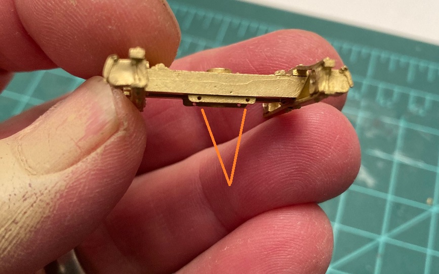
3. If you are intent on keeping the wire mounts for the brake beams, pull each of them in toward the centerline. Your wire to wire distance is currently 0.34". The distance between the two wires that support my cast brass brake beams is 0.26". The current location of the wires limits movement of the wheel set as you are trying to insert it. When you seat one axle in a journal hole, then gently spread the opposite side frame to seat the other end of the axle, you are actually transmitting force down the length of the axle and spreading the opposite side frame a bit as well. The current wire locations trap the wheel, prevents the axle from moving backwards and requires the one side frame to be spread even further (that's when mine break).
4. I'd widen the flange grooves by about 0.020", 0.010" each way.
5. I would prefer that the bottom of the transoms be printed full width--there is plenty of room for a 2 mm screw head in between. And if you could print 4 divots on the bottom, the same distance from the centerline as the brake beam holes, that would give me a drilling mark for my wire eyelets. Unless . . . the other option would be to print a small flange on the inside surface of the transom bottoms, like on the bottom of the transom of these TLS brass trucks, with the two holes for brake beam wires located so they are flush with the transom bottom:
The holes in the flange take the place of the eyelets--just insert two straight pieces of wire, glue in place, then slip the brake beams in on each end.
Is there any solvent or glue to be used to repair the broken acrylic parts? Is there a solvent that will melt and weld the stuff, like MEK welds styrene together?
Jim
URL: http://c-sng-discussion-forum.254.s1.nabble.com/Type-C-UP-trucks-tp15497p16748.html
Michael, I do love these trucks, just what the doctor ordered! I've ordered two more prints of the current iteration to experiment with.
But they need to be durable to operate, and this iteration, even in S scale, is a bit too fragile. I snapped off another side frame trying to carefully remove a wheel set, so I could prime the truck. The weak point of the side frame are the three "bars" of the archbar, especially the top and bottom, where they attach to the side of the transom.
My suggestions:
1. Beef up the bars. Yours measure 0.012' thick by 0.050' wide. By comparison, Eric's RGM white metal side frames are 0.015" thick and 0.060' wide. PBL's one piece Delrin archbar truck has bars 0.018" thick at front edge and 0.060 wide, but they engage in a bit of trompe l'oeil--the top and bottom bars have a top surface that is flat, but the bottom surface falls away at an angle, creating a triangular cross section. The front of the bar is 0.018" thick but the back surface is 0.025" thick. I like the delicate look of your current arch bars, but similar dimensions probably wouldn't be noticed. Besides, the real eye candy of your trucks are the journal boxes with the beautifully detailed lids and the center plate with its circular cutout, visible springs and tie rods.
2. Do everything possible to minimized spreading the side frames. If possible, spread the inside surface of the side frames about 0.020" total, make the axle holes more shallow by 0.010". The PBL axles fit the current axle hole dimensions perfectly. As long as you don't mount a hinky wheel set, they roll very, very well.
3. If you are intent on keeping the wire mounts for the brake beams, pull each of them in toward the centerline. Your wire to wire distance is currently 0.34". The distance between the two wires that support my cast brass brake beams is 0.26". The current location of the wires limits movement of the wheel set as you are trying to insert it. When you seat one axle in a journal hole, then gently spread the opposite side frame to seat the other end of the axle, you are actually transmitting force down the length of the axle and spreading the opposite side frame a bit as well. The current wire locations trap the wheel, prevents the axle from moving backwards and requires the one side frame to be spread even further (that's when mine break).
4. I'd widen the flange grooves by about 0.020", 0.010" each way.
5. I would prefer that the bottom of the transoms be printed full width--there is plenty of room for a 2 mm screw head in between. And if you could print 4 divots on the bottom, the same distance from the centerline as the brake beam holes, that would give me a drilling mark for my wire eyelets. Unless . . . the other option would be to print a small flange on the inside surface of the transom bottoms, like on the bottom of the transom of these TLS brass trucks, with the two holes for brake beam wires located so they are flush with the transom bottom:
The holes in the flange take the place of the eyelets--just insert two straight pieces of wire, glue in place, then slip the brake beams in on each end.
Is there any solvent or glue to be used to repair the broken acrylic parts? Is there a solvent that will melt and weld the stuff, like MEK welds styrene together?
Jim
Jim Courtney
Poulsbo, WA
Poulsbo, WA
| Free forum by Nabble | Edit this page |