Re: C&S #47, an Sn3 C-16 conversion
Posted by John Greenly on Dec 09, 2020; 1:55am
URL: http://c-sng-discussion-forum.254.s1.nabble.com/C-S-30-a-C-16-conversion-tp15055p16124.html
Okay, here we go.
I apologize for the delay in responding, Jim. I hadn't done my full hand-calculated analysis of these cabs, the way I did, for instance, for the cabooses. With the cabs a difference of 4" or so is relatively small, only 6%, and I really shouldn't have made a statement about those without doing the full analysis. This was getting to be a big job to do the full work for all of them, so I decided to finally take the plunge and get the computer into it. After some research I settled on the Sketchup software package to do what I did before by hand. I got the software and first tried it out on photos of my models, so I knew the real dimensions perfectly well. Once I figured out how, it did an excellent job with those, correct within 1 scale inch or better, so then I went on to the photos in our thread here. I've now done all of them, and here are the results, in the order the photos appear above in the thread.
the photo of #47 in 1910: cab length 6'2", height 6'7" top of floor to upper edge of roof, (not to the peak as before, that's not reliable with the software). So that is indeed a much bigger cab than the folio had, even bigger than I had estimated earlier.
the photo of #21 in 1918: cab length 5'11", height 6'10" to roof edge, again, no relation to the folio, and even bigger than my earlier result.
now to the earlier wood 4-panel side cabs,
first the photo of #22 on the turntable: cab length 5'2", height 6' to top edge. --folio, OK!
the photo of DL&G 162 (C&S 22) with certainly the same cab: cab length 5'2", height 6'. --folio, yes.
and then, two with the sheet metal riveted to the sides:
the closeup photo of #21 in 1909, cab length 5'2", height 6'0". --folio yes.
And finally, the photo I referred to above of #13 at Central City in 1903, length 5'2", height 6'0'. --folio, yes.
So, my summary at present is that the earlier four-panel cabs, which were not original to the South Park engines but were standard by the 1890's, (maybe a UP thing?) were the ones that the folios measured as I had originally assumed and Jim also suggested. At least some, probably many, of those 4-panel cabs received the sheet metal covering that #13 and # 21 show in our photos, with overall dimensions unchanged. But then at some later time larger cabs showed up. The big cab on #21 in 1918 certainly doesn't bear any resemblance to the old 4-panel. The real puzzler of this bunch is the photo of #47. That cab, other than appearing to be much longer, looks like it could have been the old 4-panel with sheet metal. But no, it can't be, it really is much longer.
So, forget about my speculation about inside dimensions, I should have stayed with my first assumption that the cabs had been changed after the folios. I guess I'll go back and caveat my posts above to avoid taking future readers down that wrong speculative path.
Meanwhile, I'll give you an example of how I'm doing these, here's the Sketchup analysis of the photo of #21, to show you how it looks when done:
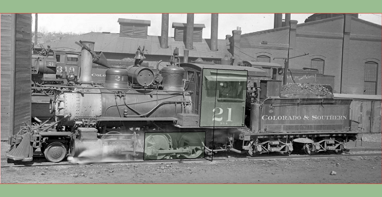
This is done by fitting a 3D axis system to the photo. That's done by hand using the software, by the operator (me). You start by finding a pair of parallel lines in each of two orthogonal directions on the object. The software uses these to determine the vanishing point of the image and thus the position of the camera with respect to the objects in the photo, and this then defines the 3D axes that you can then orient drawn lines to. The computer does those calculations for me instead of me doing them by hand, and that saves a huge amount of time.
Thus the black overlaid lines you see on the photo are not oriented to the flat photo, but to those 3D axes that have been defined. So, in particular, that short oblique line segment linking the rectangle around the drivers to the vertical line up to the cab lies parallel to the horizontal axis perpendicular to the rail. That line is 2' long, which is the approximate distance along that axis from the plane of the face of the drivers to the plane of the side of the cab. The cab side plane is closer to you than the driver plane, so to scale from the known wheelbase dimension to the side dimension you must include this offset. The sensitivity of the result to this length doesn't require it to be exact, but it definitely can't be neglected to get results to within an inch. Real care is needed in accurately aligning the axes, and I found that several iterations were often needed to get the two rectangles around drivers and cab to conform exactly to their respective subjects. Having done this several times now I've gotten a feel for how good this needs to be for accurate scaling from the wheelbase to the cab. It is much better to use as much of the wheelbase as possible rather than a single driver, for an accurate result. This is still not a trivial thing to do, but it is MUCH faster than doing it by hand!!! To do this with buildings or other simpler shapes with mostly plane surfaces and right angles, the computer can choose the edges and define lines by itself, and speed up the process still more. It's a very nice tool. I spend way too much of my life with computers and I was resisting doing this, but now I'm very glad I did, I'm happy to have it.
Cheers,
John
oh, and by the way, the cab letters do measure 18" tall.
URL: http://c-sng-discussion-forum.254.s1.nabble.com/C-S-30-a-C-16-conversion-tp15055p16124.html
Okay, here we go.
I apologize for the delay in responding, Jim. I hadn't done my full hand-calculated analysis of these cabs, the way I did, for instance, for the cabooses. With the cabs a difference of 4" or so is relatively small, only 6%, and I really shouldn't have made a statement about those without doing the full analysis. This was getting to be a big job to do the full work for all of them, so I decided to finally take the plunge and get the computer into it. After some research I settled on the Sketchup software package to do what I did before by hand. I got the software and first tried it out on photos of my models, so I knew the real dimensions perfectly well. Once I figured out how, it did an excellent job with those, correct within 1 scale inch or better, so then I went on to the photos in our thread here. I've now done all of them, and here are the results, in the order the photos appear above in the thread.
the photo of #47 in 1910: cab length 6'2", height 6'7" top of floor to upper edge of roof, (not to the peak as before, that's not reliable with the software). So that is indeed a much bigger cab than the folio had, even bigger than I had estimated earlier.
the photo of #21 in 1918: cab length 5'11", height 6'10" to roof edge, again, no relation to the folio, and even bigger than my earlier result.
now to the earlier wood 4-panel side cabs,
first the photo of #22 on the turntable: cab length 5'2", height 6' to top edge. --folio, OK!
the photo of DL&G 162 (C&S 22) with certainly the same cab: cab length 5'2", height 6'. --folio, yes.
and then, two with the sheet metal riveted to the sides:
the closeup photo of #21 in 1909, cab length 5'2", height 6'0". --folio yes.
And finally, the photo I referred to above of #13 at Central City in 1903, length 5'2", height 6'0'. --folio, yes.
So, my summary at present is that the earlier four-panel cabs, which were not original to the South Park engines but were standard by the 1890's, (maybe a UP thing?) were the ones that the folios measured as I had originally assumed and Jim also suggested. At least some, probably many, of those 4-panel cabs received the sheet metal covering that #13 and # 21 show in our photos, with overall dimensions unchanged. But then at some later time larger cabs showed up. The big cab on #21 in 1918 certainly doesn't bear any resemblance to the old 4-panel. The real puzzler of this bunch is the photo of #47. That cab, other than appearing to be much longer, looks like it could have been the old 4-panel with sheet metal. But no, it can't be, it really is much longer.
So, forget about my speculation about inside dimensions, I should have stayed with my first assumption that the cabs had been changed after the folios. I guess I'll go back and caveat my posts above to avoid taking future readers down that wrong speculative path.
Meanwhile, I'll give you an example of how I'm doing these, here's the Sketchup analysis of the photo of #21, to show you how it looks when done:
This is done by fitting a 3D axis system to the photo. That's done by hand using the software, by the operator (me). You start by finding a pair of parallel lines in each of two orthogonal directions on the object. The software uses these to determine the vanishing point of the image and thus the position of the camera with respect to the objects in the photo, and this then defines the 3D axes that you can then orient drawn lines to. The computer does those calculations for me instead of me doing them by hand, and that saves a huge amount of time.
Thus the black overlaid lines you see on the photo are not oriented to the flat photo, but to those 3D axes that have been defined. So, in particular, that short oblique line segment linking the rectangle around the drivers to the vertical line up to the cab lies parallel to the horizontal axis perpendicular to the rail. That line is 2' long, which is the approximate distance along that axis from the plane of the face of the drivers to the plane of the side of the cab. The cab side plane is closer to you than the driver plane, so to scale from the known wheelbase dimension to the side dimension you must include this offset. The sensitivity of the result to this length doesn't require it to be exact, but it definitely can't be neglected to get results to within an inch. Real care is needed in accurately aligning the axes, and I found that several iterations were often needed to get the two rectangles around drivers and cab to conform exactly to their respective subjects. Having done this several times now I've gotten a feel for how good this needs to be for accurate scaling from the wheelbase to the cab. It is much better to use as much of the wheelbase as possible rather than a single driver, for an accurate result. This is still not a trivial thing to do, but it is MUCH faster than doing it by hand!!! To do this with buildings or other simpler shapes with mostly plane surfaces and right angles, the computer can choose the edges and define lines by itself, and speed up the process still more. It's a very nice tool. I spend way too much of my life with computers and I was resisting doing this, but now I'm very glad I did, I'm happy to have it.
Cheers,
John
oh, and by the way, the cab letters do measure 18" tall.
John Greenly
Lansing, NY
Lansing, NY
| Free forum by Nabble | Edit this page |