fabrication techniques: soldering

123

123
Re: fabrication techniques: soldering

|
Jim,
The term "white metal" covers a multitude of sins- er, that is, alloys. Some that are used for casting melt below the boiling point of water, and some, like the zinc-aluminum-magnesium-copper alloy called zamak that used to be (probably still is) commonly used for die cast models, melt at nearly 400C. Many white metals are not eutectic alloys and have a wide temperature range between fully solid and fully liquid, so when heated just above solid they don't immediately flow, they are kind of goopy like grease, or maybe peanut butter, and you can sort of blend two parts together without added solder. But that's a pretty risky method! I had no idea what the Railmaster kits were made of and I was curious so I looked around a bit. Derrell Poole has a nice article on his 7th St shops site about building Railmaster kits, and he says that 275 degree solder can be used (presumably Tix) but only with great caution because the metal melts not much above this. There are other solders that melt even below 100C, and Derrell mentions using one of those, didn't say which alloy. As to flux, I assume water-soluble acid flux like Stay-Clean or Tix, but I don't know for sure. I dimly remember trying to solder zamac when I was a kid and failing to get solder to wet it, but that was probably with rosin flux. One caution: a lot of the super-low melting alloys, solders and white metals, have nasty stuff like cadmium in them. Very not good to breathe the vapor from the liquid state. John Note added: I didn't see Paul R's post until after I finished this. Thanks for the supplier info!
John Greenly
Lansing, NY |
Re: fabrication techniques: soldering. Carrs solders
|
|
This post was updated on .
At Paul's suggestion, I googled Carrs solders:
International Hobbies carries the full line: http://www.interhobmodels.com/id17.html 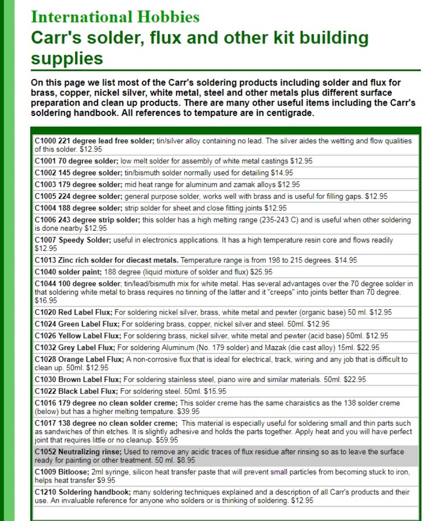 Located in California, you can order by phone or email, they take Visa, MC, AMEX. 530-268-8715, interhob@gmail.com And C&L Finescale, a Brit firm, has a table of recommended Carrs solders and fluxes per planned uses: http://www.finescale.org.uk/index.php?route=product/category&path=453. Scroll to bottom of page. All kinda' neat stuff here -- thoughts folks?? The C1016 179 degree C solder cream looks interesting for those nickel silver etchings. The C1044 100 degree C looks to be perfect for white metals.
Jim Courtney
Poulsbo, WA |
Re: fabrication techniques: soldering. Carrs solders
|
|
This post was updated on .
Jim, yes, I found the same things last night, this is very interesting, many thanks to Paul for this!
There is on that Finescale site also a brief guide to soldering with some nice discussion: http://www.finescale.org.uk/index.php?route=information/information&information_id=29 I note especially that this strongly emphasizes my earlier point about avoiding paste fluxes. But also, it says that model work seldom uses 60-40 tin-lead solder. I still use it because it has such excellent wetting and flow properties, protects the iron tip, etc. Other lead-free solders I have tried just don't work as well, but if one of these Carr's solders is as good in that melt temperature range I'd be happy to switch. That article mentions an important property of 60-40 solder, namely the narrow temperature range between fully solid and fully liquid. Some alloys are eutectic, meaning that the melting and freezing temperatures are identical (60-40 is very close, the eutectic alloy of tin and lead is about 63-37), while others have a wide range, the full melt temperature is higher than the full freeze temperature, and in between the material is in a pasty, gloppy state. If the joint is disturbed mechanically, moves slightly while the solder is cooling through this state a "cold" joint can result, weak and brittle. So eutectic or near-eutectic solder alloys are advantageous for this reason. Stay-brite and Tix are both very good this way. as well. The first solder on their list, the C1000 221C tin-silver solder, is probably identical to Stay-Brite. The C1002 145C solder melts only 10C above Tix, but I would still suggest trying Tix because it has such nice working properties. There's a reason it's been a standard for jewelers for so long. Don't get too fixated on melt temperatures, the other properties are really important. I think I'll get the C1210 soldering handbook to learn more. One other thought. That solder cream does sound very interesting. I wonder about two things. Can it be applied thin enough not to have an excessive amount of solder and flux between two close-fitting surfaces? You need, and want, only a tiny amount of solder. And what happens when you melt it: when you feed in solder from one edge of a joint, the flow pushes the flux out the other side and makes a perfect joint. What happens to the flux, and any air pockets, in a joint prefilled with the cream? Maybe you put on the cream and squeeze it out the edges before you heat? Maybe it's just right, I don't know. British modelers have been doing exquisite things with brass for a very long time, so I'm going to follow up on this! Again, Paul, thanks for putting us on to this!! John and, I just ordered myself some Tix, thanks again to Pat for reminding me!
John Greenly
Lansing, NY |
Re: fabrication techniques: soldering
|
|
This post was updated on .
In reply to this post by South Park
S.P.,
those turn signals with the arrows are perfect. If only they would be bigger than 1/32" across in HO scale, I'd add them to my model of your truck for sure! John 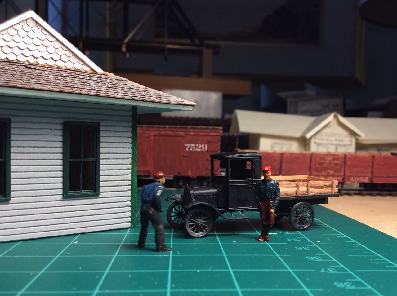
John Greenly
Lansing, NY |
Re: fabrication techniques: soldering. Questions . . .
|
|
In reply to this post by John Greenly
OK John, I've ordered some Stay-Bright and Tix solders and fluxes. Will likely call about some of the Carrs products tomorrow.
Now for some stupid soldering questions: Tips on tips -- I have two Weller irons and a PBL resistance soldering set. The 35 watt Weller iron I use for assembling track switches in the Fast Tracks assembly fixtures. The other Weller iron is temperature adjusted 350-850 F. I use a fine conical tip on the little Weller iron, to heat the rail at the web using the fine tip, heating the fluxed PC copper tie beneath as well. I have a larger conical tip on the adjustable iron. Your photo shows that you use a larger chisel shaped tip. Does that allow a greater amount of heat transfer to the work, without fall off in the iron's tip temperature? What do you recommend? Tinning -- How do you tin your irons? Before, during or after the work? I use the tinning paste that comes in the little can with soldering stations. What is the best way? The Fast Tracks guy suggests plunging the hot tip into acid paste flux, then whipping it off on a roll of paper towels, adding solder back to the iron. Is this stupid? Castings -- How would you attach substantial lost wax brass castings to a locomotive boiler (ie an air pump, or a generator)? I use my PBL soldering tweezers on the high setting, to heat up the entire casting, with flux and small amounts of solder on the joining surface to "tin" the casting. After it cools, I then position the part onto the fluxed boiler area with the tweezers, apply current with the foot petal, hold everything still until the solder melts and flows in the joint. I cut off the current and continue to hold things perfectly still until the solder solidifies completely. Holding everything in perfect alignment for 30-40 seconds while things heat up and cool down can be challenging, and the part may drift or float out of alignment when the solder is in the liquid state. Adding brass locating pins of 0.020 or 0.025 wire tends to help keep things aligned. Is there a better way? Do you use an iron to heat the castings? Does a torch work better? Thin wire solder -- Fast Tracks sells a 60-40 solder in 0.020" diameter; PBL sells a lead free solder of 0.015" diameter. Are there others? Filling holes -- There are times when one wants to remove a part or move a part to another location on a boiler, or say grab irons on a brass caboose body. That leaves a hole in the brass to fill. Can solder be used to fill said hole? Does one need to put a piece of thin brass sheet inside the boiler, under the hole and build up solder on that base? I've been experimenting over the years, still haven't mastered this skill as yet. (As Derrell Poole once remarked, "The only thing that sticks to brass is fingerprints."). Rather than re-create and evolve my own wheel, I'd appreciate any and all advice, from you, Pat, Paul, et al.
Jim Courtney
Poulsbo, WA |
Re: fabrication techniques: soldering. Questions . . .
|
|
Jim
For castings, say changing a head light, my best success is using a the larger Weller soldering gun. Lot of heat in a short time. For filling a hole, I solder a piece of wire oof the same diameter of the hole and clip off the excess, the file / sand smooth. I've seen some work where the hole was filled with solder, my luck is that I end up with a dimple on the finish side. Also the solder fill can fail from heating to attach another detail nearby, whereas the wire fill hasn't failed me. Do the heating from the wrong side when possible. Tinning the tip. Not necessary for a resistance unit. Others, tin before use. Apply a little flux, the melt a little solder. I keep a very small steel brush handy to clean the tip of excess solder or burnt flux, a few strokes and the iron is ready again. Solder size. I basically match the diameter of the solder with the joint size. Most of the details we attach, the 0.020' or there about is sufficient. A head light with an integral mounting pin through the boiler, I'd go to a size approximately the size of the mounting pin. On comment about choice of solder to use. If there's a chance the that the position of the attachment may need to be tweaked or I may need to disassemble and start over, I stay away from silver solders and used tin-lead only. Silver makes the joint too "permanent". Like welding, too little heat won't work. Getting started is harder than doing. Practice on something that is a throwaway. Apply some hand holds to piece of brass sheet, join some pieces of brass tips, etc. Pat |
Re: fabrication techniques: soldering. Questions . . .
|
|
This post was updated on .
In reply to this post by Jim Courtney
Jim,
I'll add a few bits to Pat's good advice. As to your specific questions, Tips: Yes, you saw that I used a chisel-shaped tip for the water hatch. My general rule is to use the largest and shortest tip that can fit where it needs to go. The reason is indeed for best heat transfer from the iron. Short and fat is good to conduct heat faster from the heating element, and the flat of the chisel shape can, depending on the shape of the work, give a bigger area of contact of tip to work than a round cylindrical or conical tip. The flat also holds a small amount of solder nicely to feed into the joint. But, I use a half dozen tip shapes including conical of differing sizes. They are changeable on my iron in a few seconds while it is hot, and I use the one that gives me the best contact area to match a given piece of work. Tinning: I didn't do a good job of defining tinning in my first post. Tinning a surface just means coating it with a nice, continuous, not spotty, layer of solder. (The term comes from old-time tinkers who coated iron or copper pots with tin to make food taste good. Fancy French copper pots are still tinned). Tin an iron tip by feeding it some solder to cover the surface. The iron tip needs to be tinned to protect it from oxidation that prevents it from wetting, and I hope I have made it clear that a wetted tip is an absolute prerequisite for good soldering. The liquid solder itself conducts the heat from the tip to the work (except for very tiny jobs that need very little heat). To tin the tip it must be clean and not oxidized. If you keep the tip tinned all the time it is hot it will stay good. If you cook it for any time while dry, it will go bad. Using rosin core solder for tinning is okay, you clean and tin the tip at the same time so the clean tip is never bare. Those tinning pastes can do the same thing. If you need more cleaning power, there are numerous methods. You can use paste flux, I mentioned a very good one in my first post. But in all cases, whatever flux or other cleaning agent you have used must be removed right away. You need to get it all off, or it will cook on the tip and wreck it eventually, and also you don't want any to get on the work. Wipe flux, and excess solder, off completely with a folded up paper towel and immediately re-tin. Lots of people including me use a damp sponge to wipe on after flux has been applied- the steam helps dislodge it. Or wipe on one of those copper things that look like a pot scrubber. I like those too, but not needed unless you cook flux on. Use a sal ammoniac (ammonium chloride) block - this is amazingly wonderful for reconditioning an oxidized or not-wetting tip. Do all of the above as necessary. Keep the tip tinned all the time, then no worries! So the answer to your question- tin before, during or after?- is: Yes. Attaching castings- I don't have experience with resistance soldering so I have no opinion about it. I like to use the butane microtorch for several reasons. First it can provide heat at a very high rate so you can solder at one spot before the rest of the assembly gets too hot. Second, no physical contact means that parts don't get nudged out of position. The flame can be directed to heat the casting, but if you don't heat the mating part adequately too you won't get the solder to flow on that surface and a bad joint will result. The torch flame can be directed to do both simultaneously. Another important reason for fast heating is to avoid evaporating or burning away all the flux and oxidizing the surface before it's hot enough to flow the solder. Sometimes it's necessary to re-apply flux to a large workpiece as it heats. Think about how heat will flow within and between the parts you're working with. Generally you want to apply most of the heat to the part that has the larger thermal mass. For instance, to attach a grabiron to a hefty end beam, tin the grab, then heat the beam. As the beam heats the grabiron follows along, and when the tinning melts the job is done. I illustrated this with the hinges and the handle on the water hatch. With an air pump, you'll have to heat both it and the boiler. The boiler tube may be thin, but it's conducting heat away over a large area, from the joint to the larger surrounding mass: a heat sink. Another important reason for fast heating is to avoid evaporating or burning away all the flux and oxidizing the surface before it's hot enough to flow the solder. Sometimes it's necessary to re-apply flux to a large workpiece as it heats. I like tools that have more than enough power to do the job. That's why I use a 36-grit 7 inch disc grinder to do initial fairing on boat hulls. One slip and you've destroyed it, but the job gets done fast! The torch is a bit like that for soldering. I don't know about the resistance tool, but your description sounds hopeful to me. Lots of heat with that in a well localized area, yes? But does it apply heat to a very small area, and is that prone to overheating and oxidizing? The torch is very flexible, you can move it around fast to cover exactly the area you want. It takes practice but it's a great instrument, you can play any tune on it. Locating pins are good, as we agreed before, to make accurate and strong mounting. I'm usually too lazy to do that though. With the torch, and suitable orientation of the work, good old gravity can often hold the part happily in place, as long as (here I go again) you don't give it too much solder to float around on. Thin wire solder- yes. As I mentioned, I use .020" solid core tin-lead solder (actually 63-37 tin-lead, I somehow came upon a one-pound roll ages ago, a supply for the next few lifetimes). The Stay-Brite and Tix are larger diameter, but as Charles or Pat pointed out, you can flatten them out thin and cut off tiny pieces easily. If you have small solder you can always use more of it. If you have larger solder it's harder to use less of it. In any case, I seldom feed solder from the roll onto the work, too hard to limit the amount melted just right. The solder is either already on the part, or on the iron tip before it's applied to the work- both of which I illustrated with the water hatch fabrication. The plumber's "flux it and feed it" regime is not for us makers of small things. Unless maybe you are modeling a foundry floor, with great puddles of spilled molten metal.... That sounds like fun! I visited an aluminum foundry once, it was dangerous because molten aluminum is not red hot, it looks just like cold aluminum, so you couldn't tell whether spilled stuff was liquid or cold. Don't try to pick up an interestingly shaped drip! Filling holes- Pat's got the best method. If you just try to fill it with solder, you get an untrustworthy dimple, exactly as he says. And especially note his advice to solder from inside- or whichever side can't be seen. Then you can make a nice big strong fillet of solder to hold the wire best. Finally, I beg to differ with Derrell. Au contraire! Fingerprints and other such nasty surface-befoulers are what keep solder from wetting. Cleanliness and flux-iness are the answer! You've never known how attractive brass can be to solder until you've used Stay-clean flux (or Tix or other similar). Instant-flowing solder and complete happiness will follow! Why am I using all these exclamation points? and, yes, do practice, and do it on parts of the same thickness and size as the real thing, to learn how to manage heat as you want. I should have said right in the beginning that a proper solder joint is defined by the surfaces being wetted. Just like how water wets a surface rather than beading up. That's what you're aiming for. If it's not happening, then the surface isn't prepared or fluxed properly. John
John Greenly
Lansing, NY |
Re: Fabrication Techniques: Soldering. An ongoing tutorial??
|
|
John and Pat,
Thank you for all the educational points that you've shared with respect to the art of soldering. This may be the most useful thread thus far posted. I'd like to suggest that we regard John's thread as an ongoing tutorial for fabricating model parts from metals with soldering. If anyone of us takes on a project requiring soldering and find ourselves stuck, not sure how to proceed, perhaps we can post a "Dear John" letter and ask John, Pat and others for help, suggestions, etc. Might even make a good "sticky" thread, Darel. I'd love for John to post more illustrated "how to" descriptors as he continues to work on his C&S Rhode Island and F&CC locomotives. How he plans to add window frames to the inside of the cab, attaching castings, etc. Once I stock up on the necessary solders and fluxes, I'd like to press on with a project of my own. I don't yet have the courage to take on the Cooke 2-8-0 project from Bill Meredith's nickel silver etchings just yet. But I do have the largest collection of disassembled Overland Sn3 C&S locomotives in the known universe . . . and I've been collecting S scale brass castings that might be useful for backdating C&S locomotives wherever I have found them (Precision Scale, PBL, Theo Berlyn, The Leadville Shops, etc). So, time to start putting them back together! I think this will be my first project, starting with an Overland C&S B-4-D number 65: 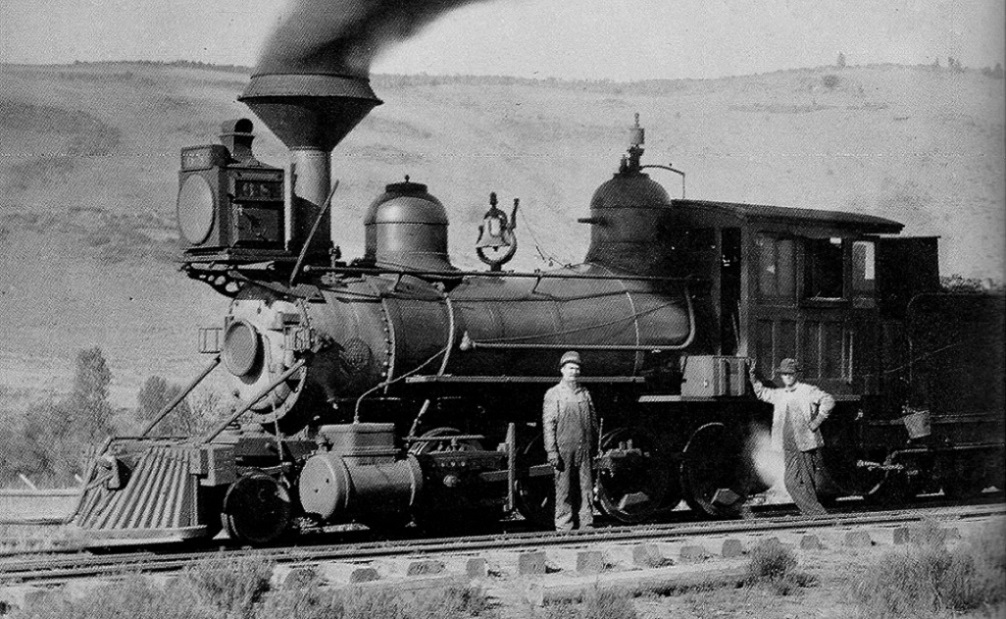 Parlins, c1901, C&S number 68. Digerness, The Mineral Belt, Volume 2. I'll post photos and ask questions as I go along or get stuck. It will be a nice to alternate work between the printed HOn3 RPO 11 project and working in brass.
Jim Courtney
Poulsbo, WA |
Re: fabrication techniques: soldering. Questions . . .
|
|
In reply to this post by John Greenly
Kelley Morris had some good articles on detailing brass locomotives in the Gazette back in the 1980s. I started working on brass models back in the mid 1970s with a 25 watt iron and a Microflame torch. Most of the work was done with the torch using several size tips available at the time. I also got into resistance soldering in the late 70s or early 80s. It works well but you sort of have to use different techniques than with an iron or torch. PBL sells a DVD on soldering for $25 that has a focus on working with resistance units and on models. You have to be careful with resistance because you can melt castings and wire. You can also get pitting from arcing if using poor technique and tips that need filed clean on tweezers.
Today I use the resistance unit and a Weller temperature controlled station. I mostly use an 80 watt handpiece with a variety of tips. There are probably about 20 different tip sizes and shapes for the handpiece. The tips last a very long time but only cost about $5-$6 each. These setups are a few hundred dollars but you can handle a huge range of soldering tasks. I solder leads to nano LEDS, turnouts, decoder installs, and model components. The 80 watt handpiece with a larger tip can put out a lot of heat quickly. There are also smaller and larger wattage handpieces available too. The iron coming up to temp only takes a few seconds. Depending on the control station you can even run several handpieces at the same time or switch back and forth. You can also program several different temperatures which can be selected by pushing a button on the control station. I highly recommend this type of station if you are serious about soldering. Consider it a quality tool you will own and use for a long long time. I find it easier to teach people to solder with quality equipment. One thing I used to often do especially with using a torch or the resistance unit is to cut small slivers of solder and heat them on a carbon block or other non stick solder surface and let them form small spheres of solder. These small balls can be placed with the tip of an xacto knife or tweezers on a seam you want to solder with the flux holding it into place. Apply heat and the flux will melt and the solder will flow. I think the big mistake people use is using too large of diameter solder and getting too much solder that then looks bad and needs more cleanup time. I notice a lot of people soldering track tend to end up with globs of solder. I have even soldered HO scale etched Proto87Stores.com tie plates to rails using my resistance tweezers. It can be done fairly easily. I use a lot of 0.010 diameter rosin core solder. It makes it easy to not get too much solder. If I need more and larger diameter solder I just unroll a couple feet of this very fine solder and fold it back on itself once, twice or more and give it a twist to make a larger diameter solder. I have also used Stay Bright solder and flux in the past. I tend to not get to concerned with the melting temperatures as I sort of learned to use technique in the days when not a lot of solders were easily available, at least in my world. Hemostats can also be used as heat sinks as well as using locking tweezers and alligator clips. The resistance tweezers are also nice as you can hold things in place, heat and then hold while the joint solidifies. Also it is important to remember that solder flows toward the heat. One can use that to your advantage if you keep it in mind. I have several tips for my Weller handpiece that have an 0.008" tip point. It is impossible to apply solder to that tip without it migrating up the tip seeking more heat... PBL offers some nice solders and fluxes also as well as solder wick. Solder wick is handy for removing excess solder with an iron. I use All-Spec in North Carolina for soldering supplies, they have a website and number you can call. Jewelry supply houses are also sources for soldering equipment, mainly torch based stuff though. |
Re: fabrication techniques: soldering. Questions . . .
|
|
Pat and Todd,
Do either of you find much use for the carbon probe that is part of the PBL resistance soldering set? I've owned mine for 10 years and only seem to use the tweezers. If you use the probe, for what specific uses?
Jim Courtney
Poulsbo, WA |
Re: fabrication techniques: soldering. Questions . . .
|
|
Jim, I don't find myself using using the probe very often. I would probably look at using it for some heavy soldering like doing frame soldering or heating a large casting like a pilot or compound air pump. The inconvenience is that you have to clip the other strap to the model too to complete the circuit. I have seen Bill Peter clamp a model into a panavise and attach the clip to the vise and use the probe. The probe to me feels more like welding than soldering. It is good to have but the tweezers are my go to for most work. The tweezers will turn red hot at high settings pretty quickly...I have the 300 watt unit. It can be a good idea to have some wet cloth or paper towels as large castings can hold a lot of heat for longer than people think. I got my fingers burned by a cross compound air pump a couple times in the early days. So, having a wet towel to drop on the work can help cool it faster.
I recommend people check out the PBL soldering DVD if they are interested in resistance soldering ...it is only $25 and I think they credit it if you buy a unit from them. It comes with the new units perhaps too. For the more budget minded you can build your own unit. I think Craig Symington, who writes for the Gazette, did his own based on a battery charger. I gave him a 74 from Wesrside that was a project I started and didn't finish. He was going to do it as RGS 74. Maybe he will do an article on it some day. |
Re: fabrication techniques: soldering. Questions . . .
|
|
This post was updated on .
In reply to this post by Todd A Ferguson
Todd, thanks for your great contribution to the thread!
A couple of additions, and a question: Your use of tiny balls of solder reminds me that a company called SRA sells solder spheres of a variety of sizes for exactly the purpose you described, that is to accurately meter the amount of solder supplied to the joint so that you don't have excess. Here's a link to one of their range of sizes: https://www.amazon.com/Sphere-Solder-Balls-0-25-63/dp/B00P76G5JM/ref=sr_1_2?ie=UTF8&qid=1546130819&sr=8-2&keywords=sra+solder+balls I haven't used them because I do this by cutting off tiny bits from wire solder as necessary. But I imagine it would be quite convenient to have spheres of uniform size. Especially if you were doing multiple iterations of the same job, you could get very exact results. SRA also makes a wide range of different solders and fluxes and sells other good soldering supplies and tools. I understand what you mean by saying that solder "flows toward the heat". Solder is less viscous at higher temperatures so it spreads faster to hotter areas, and of course won't spread at all to areas below the melting temperature. But your statement might be a bit confusing to a beginner, because solder does of course also flow wonderfully well away from the heat source, like the iron tip, into a properly fluxed joint, by capillary action. So you can heat one edge of an assembly and the solder will flow to fill the joint, as I illustrated in my water hatch post, as long as the whole joint area is above the melt temp. My question is this : I'd be extremely grateful if you, or someone else among us who has also mastered resistance soldering, would post here a brief introduction to the art. How does it work? Heat is generated as current flows through a resistance. But where is that resistance in the soldering setup? Do the tweezers themselves heat up, or the contact point between the tweezers and the work, or the joint between the parts, or the parts themselves, or all of those? Where heat is generated depends upon the resistivity of the materials in the circuit- the tweezers and the parts between them- and the resistance of the contact points- poor contact could I imagine result in intense very localized heating or even arcing. I assume that the carbon probe acts as a resistance element and would itself heat, and act like a soldering iron tip, except that it wouldn't wet with solder? How easy is it to get heat applied over a desired area, versus at a very localized point? So, I'm wondering, how does resistance soldering really work in practice? I'd love to hear your insights. many thanks, John
John Greenly
Lansing, NY |
Re: fabrication techniques: soldering. Questions . . .
|
|
John, I am not sure I have any great insights into resistance soldering but I do recall seeing an article on the brass builders processes in the Far East and one thing that was interesting was that IIRC the author said that none of the builders he had ever worked with used any resistance soldering. I recall in part it was because it was too slow and inefficient compared to the large copper irons that seemed to be preferred.
It always seemed to me that the brass models that I worked on over the decades seemed to be soldered with what I would refer to as soldering paste. Many brass models especially the ones from the 60s and 70s are very rough looking on the inside or unseen areas. It in many ways reminds me of the great American furniture of the 18th century...beautiful on the outside and often very unrefined on the interior and unseen areas. Woodworking is another of my hobbies... I do recommend the PBL DVD as a worthwhile investment of $25. Plus good soldering equipment is an advantage in my view. There are also some good videos on YouTube that get into electronic soldering and some knowledge can be gained by watching how soldering of small electronic components and chips is done, especially rework of boards or mil spec soldering which is quite precise and labor intensive it seems. As to,a bit of your question about resistance I can tell you that the current flows from one tip of the tweezers to the other. If you just touch the tips together and apply current the tips will turn red hot very quickly. I believe the tips are perhaps ni-chrome wire. If you don't touch the tips together and apply current with the foot switch, no current will flow through because the circuit is broken and no heat is generated...no resistance so to speak. As you use the tweezers the tips get flux and oxidation on them an that reduces the ability to complete the circuit cleanly and I take a mill file and pull it between the tip ends to get a clean surface and restore the conductivity. The tips can also be bent and formed fairly well. I try to make sure that they are meeting each other pretty evenly and will sometimes file the ends to help them match up to each other well. The probe is similar in that the current needs to flow and complete a circuit to generate heat. The clip is one side of the circuit and the probe, usually a carbon or carbon with cladding, is the other side of the circuit. The resistance occurs where the probe touches the model or part to complete the circuit. I find the fairly large diameter of the probe to be less than an advantageous unless you are soldering heavy castings. I use the tweezers most of the time. It also takes some practice and experience to learn how the different power settings produce heat in coordination with how long you cycle the foot switch. The PBL HotTip units have 5 or 6 discrete power level settings while some other brands may have a more variable power level setting. I believe some home built units use light dimmer switches to vary the power level. Of course it also depends on the watts of power your unit puts out. One thing to use for learning is to just take various sizes of brass wire and hit it with different power levels for different periods of "on" time. The wire will heat up, become annealed and then just burn if it gets hot enough. You can also hold a penny in the tweezers and apply various power levels for different times and see how long it takes to turn red hot. Just be careful not to drop it and burn yourself...and it can still be very hot even after it appears to have cooled. Brass castings can also act this way...still hot when they appear to have cooled... But don't ask how I learned this decades ago... Some people may be tempted to buy and use the Weller gun type soldering units. They are fairly cheap, but I find them fairly useless for any quality soldering. But if you do want to used such a gun I can tell you that you can save some money by not buying the premade tips. Instead you can take 10 or 12 gage copper electrical wire and bend your own tips for pennies each in a couple minutes. You can also bend wire to shapes and use them as foam cutters if that is used on your layout. You can also form wire to shape and mount in in wood blocks and connect it to the resistance unit outputs and cut foam with that too. I recall an article or two on doing this in the modeling press in the past. Best, Todd |
Re: fabrication techniques: soldering. Questions . . .
|
|
In reply to this post by John Greenly
As for the solder balls, I find that if one is using solder of a consistent diameter you can cut slivers or lengths of solder and just by heating them with a small torch form them into pretty consistently sized spheres. I used this solder ball technique more when I used the microflame torch as it was quick to slice off a few lengths and ball them because the torch was on. The flux will usually hold the balls in place at a joint or seam. Of course pre tinning can also be a very effective technique too.
The balls may also be able to be formed by a heat gun if it doesn't blow them across the room. I have a Weller heat gun with tips that is for doing heat shrink primarily. But it puts out 800 degree F air so you can in fact solder with it too in theory. I have tried it just for grins and it can be done, but it is not very efficient or all that effective. In the electronic soldering world hot air soldering is much more common as well of course the oven heating of boards that are screen printed with solder paste and then oven heated to activated the solder joint forming. This is how DCC decoders are soldered. |
Re: Fabrication Techniques: Soldering. An ongoing tutorial??
|
|
In reply to this post by Jim Courtney
I hope that you mean to do it as it is in the photograph.What about a Rhode Island and a bigger Baldwin with a short smokebox?
|
Re: Fabrication Techniques: Soldering. An ongoing tutorial??
|
|
Don't have any spare Rhode Islands, Robert. They are slowly being re-detailed for the year 1909, with shotgun stacks.
Yes, I plan to redo one of my Baldwin B-4-D's to c.1901, just as in the Parlin photo. Parts are in hand, just need to get my courage up, and better fluxes!
Jim Courtney
Poulsbo, WA |
Re: Fabrication Techniques: Soldering. An ongoing tutorial??
|
|
Have you seen some of Darrell Poole's custom parts on the 7th Street Shops website?
|
Re: Fabrication Techniques: Soldering. An ongoing tutorial??
|
|
Yes Robert,
But most of the parts I will need are available in 1/64th scale from The Leadville Shops: http://www.theleadvilleshops.com/164-details 
Jim Courtney
Poulsbo, WA |
Re: Fabrication Techniques: Soldering. A wire frame
|
|
What with all this talk about soldering, you inspired me to fire up the iron and assemble the canvas cover for a truck I bought a while back.
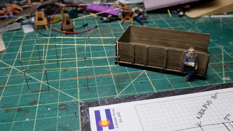 Thanks for all the tips!
Keith Hayes
Leadville in Sn3 |
|
|
Keith, that's dainty work, did you use clamps or fingers to hold while soldering? Paul R.
|
«
Return to C&Sng Discussion Forum
|
1 view|%1 views
| Free forum by Nabble | Edit this page |