Modelling stub switches
123
123
|
Great pictures of the Rockwood wye stub switch (albeit D&RGW) here:
|
|
This post was updated on .
Jeese, sometimes I think I'm getting senile! (A few years ago I was worried that I was developing early symptoms of Alzheimer's--then I forgot what the symptoms were and stopped worrying).
I've been reading this thread with interest since Jeff started it. Today, I was going through my filing cabinet to find some drawings that I wanted to scan into my computer. I spied a folder titled Colorado & Southern, Common Standards: Track and Bridges. Within the folder, I found several C&S track work drawings from the Office of the Chief Engineer, all dated 1910. I don't know how long they've been quietly hiding in the folder, perhaps from the late 1970s or early 1980s. I don't remember from where I acquired them, perhaps from the late John Maxwell? Perhaps they would be of interest in this discussion.  Evidently, the "standard' 3 foot gauge C&S stub turnout was a number 8 1/2. 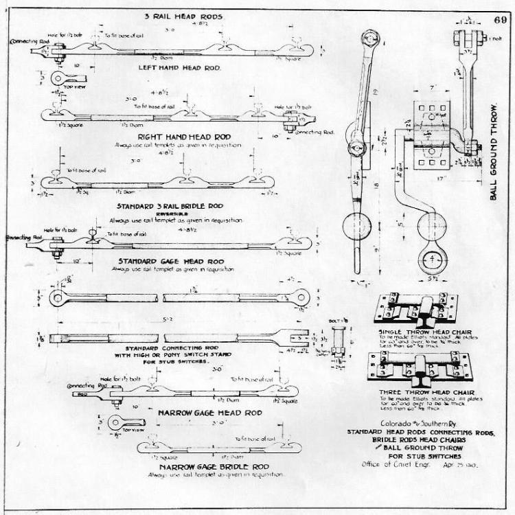 This one is for you, Chris.  I don't seem to have a similar drawing for a stub turnout. 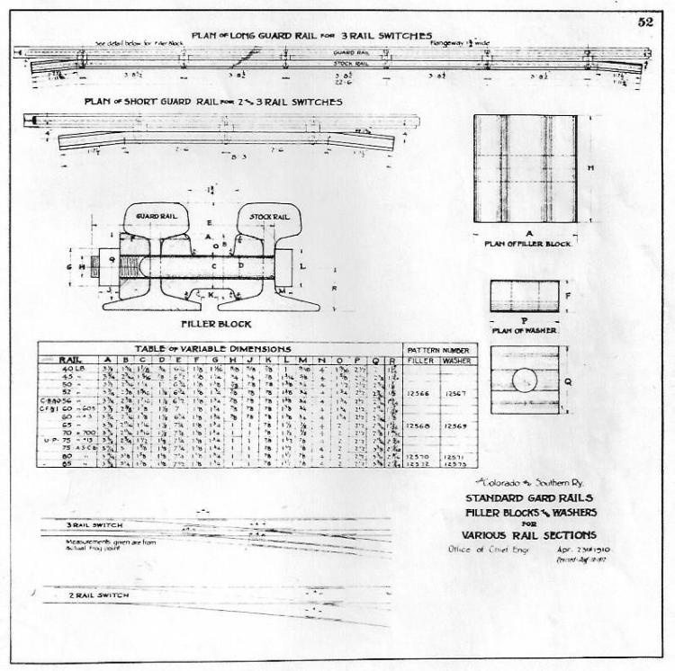 PS: I worry that many of us who post to this site are getting older and that much of what we have collected during our lifetime, about our favorite narrow gauge railroad, will get lost as our lives wind down. Perhaps it's time to clean out our file cabinets and post as much material here as we can, where appropriate, for the use of others.
Jim Courtney
Poulsbo, WA |
|
|
In reply to this post by Jim Courtney
OH ! MY! A C&S Ball Ground Throw !!!

Thanks Jim, I just have to have one of those. I really like that Eyelet on the handle! The Gilpin also had one on their Enginehouse trackage very similar but with a rectangular weight. I need another on my tramway, I built a West Side Lumber version a couple of years ago and really like it; by standing on the crank and puting my weight on the throwrod clevis, I can up-end the lever without bending over to throw the Stub.  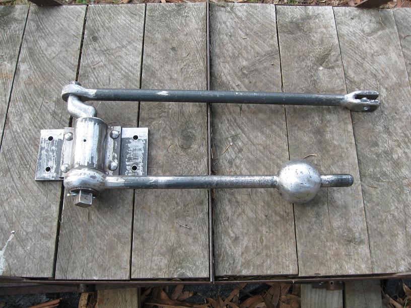
UpSideDownC
in New Zealand |
|
This post was updated on .
Finally got around to making some progress on this front.
Ties glued down, with extra-wide PC-board headblock. (Copper has been filed off headblock everywhere except where the fixed rails and stops will be soldered down.) 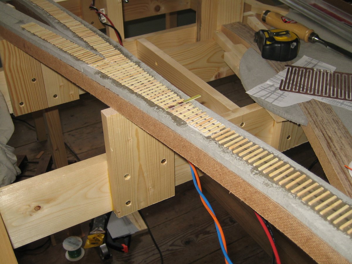 Head rod carrier and 3 bridle rod carriers. A prepped PC-board tie (ready for soldering) can also be seen. Note that the head rod carrier is a bit wider (as it will have holes drilled in it for the switch machine and switch stand). All the carriers are made out of thin PC-board (1/32") so they will slide easily under the rails. Head rod carrier is a HO-scale standard gauge tie, while the bridle rod carriers are HO-scale narrow gauge ties. 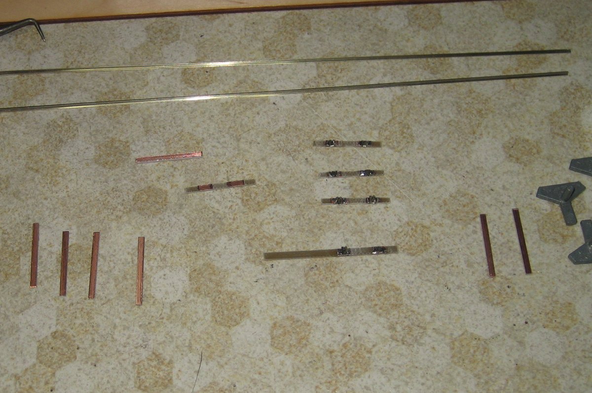 The rail joiner thirds were considerably harder to work on than expected. They're just too dang small to grip, move, hold, etc. Another lesson I learned the hard way: the rail joiner third needs to be pretty much as wide as the PC-board, otherwise you risk getting solder between the PC-board and the rail used to hold the rail joiner in gauge while soldering. The tops of the carriers still need to be covered in dirt, and the (styrene) rods glued in on top. Cheers, Jeff. |
|
In reply to this post by Bill Uffelman
Here is a link to the files Lee Kleidon put together regarding stub switch geometry and construction for the '98 narrow gauge convention clinic he did. This is some of the best info on stub switches that I know about to date. I visited Lee's Sn3 layout and he used stub turnouts only, including several 3 ways. You may need to join the yahoo group to see these files as PDFs. Or I can copy and post over here if someone can tell me how to post files here.
https://groups.yahoo.com/neo/groups/Sn3/files/_Trackwork%20-%20Real%20and%20otherwise/Stub%20Stuff/ Best, Todd Ferguson Harrisburg, NC |
|
In reply to this post by Jeff Young
Jeff and others,
Did the C&S use tie plates on all the turnout ties? Most narrow gauge didn't seem to use tie plates very often. Only slide plates under the moving rails and some strap plates under the frogs if I recall from my photos of the salvaged RGS stubs at the CRRM. I was curious when I saw you using the Proto 87 tie plates. Their throwbars might make good bridles in HO too. They work well once you get the hang of them. I think they make an HOn3 size too... Also look up turnout construction photos by Tony Sisson on the web. He made some very nicely detailed turnouts and did clinics at RPM meets back here on the east coast. Some interesting ideas he used too. Worth a look I my view. Best, Todd Ferguson Harrisburg, NC |
|
No, the C&S didn't use tie plates much. I've seen rail braces at frogs, and slide plates under moving rails, but that's about it.
I'm not planning on using tie plates (or slide plates) anywhere. ME small spikes are already quite over-scale, so they do give the impression of more being there. (I tried ME's micro spikes, but they're too hard to spike and I don't trust them to hold terribly well, so I plan to save them for trestles.) The original idea was to fabricate a chair block using modified rail joiners, but I'm now planning on using Wolfgang Dudley's simpler method of soldering stops outside the rails to mimic the chair blocks. Aside from that, the only details I'm fabricating are the head rods and bridle rods. (And I'll probably try some Proto:87 rail joint bars 'cause I liked Keith's picy.) Tony's stuff was quite cool, but I'm kind of glad the narrow gauge prototypes were simpler. It'll save me some work. ;) It'd be great to get Lee Kleidon's stuff posted here. I don't have access to the Sn3 Yahoo group.... Cheers, Jeff. |
|
Jeff,
Give the Proto 87 spikes a shot. The HO ones are close to scale, I'd go with the long ones. I use them on some HO track. They are not bad to work with a number 7 lens Optivisor. I also use the 150 percent HO spikes which are a larger version for some HO stuff and Sn3 and On3. They are similar in size to the Micro Engineering Micro spikes but because the Proto 87 spikes are etched stainless steel they are much better shaped and easier to work with in my view. Of course if you are going to paint the ties you could just go with PC ties and solder. IV tried just about every track laying method over the years so if you have ant questions feel free to ask me. Best, Todd Ferguson Harrisburg, NC |
|
In reply to this post by Jeff Young
Here is the last 'active' in situ stub I know of at Rockwood:
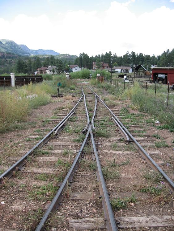 and  Not many tie plates, as you can see. One other thought for you, Jeff. In Sn3, I bought some Details West rail plates, and apply these to the viewable side of the rail on either side of the frog where there would be a joint. What if you got some Evergreen strip, cut it to length and applied some Archer rivet decals? Make sure you paint your rail brown and highlight the joint bars with some rust to make 'em pop. Though a bit labor intensive, for turnouts that are up close and up front, this could make for a nice detail that would not hamper operations! Maybe I will try this on a couple of my own frogs!
Keith Hayes
Leadville in Sn3 |
|
You can get frog, point and joint bar etched details from Proto87Stores for HO code 55, 70 and 83 rail. Lots of nice track related parts at very fair prices. I also like his Mole Switch machines...
Best, Todd Ferguson Harrisburg, NC |
|
This post was updated on .
Headblock soldered up:
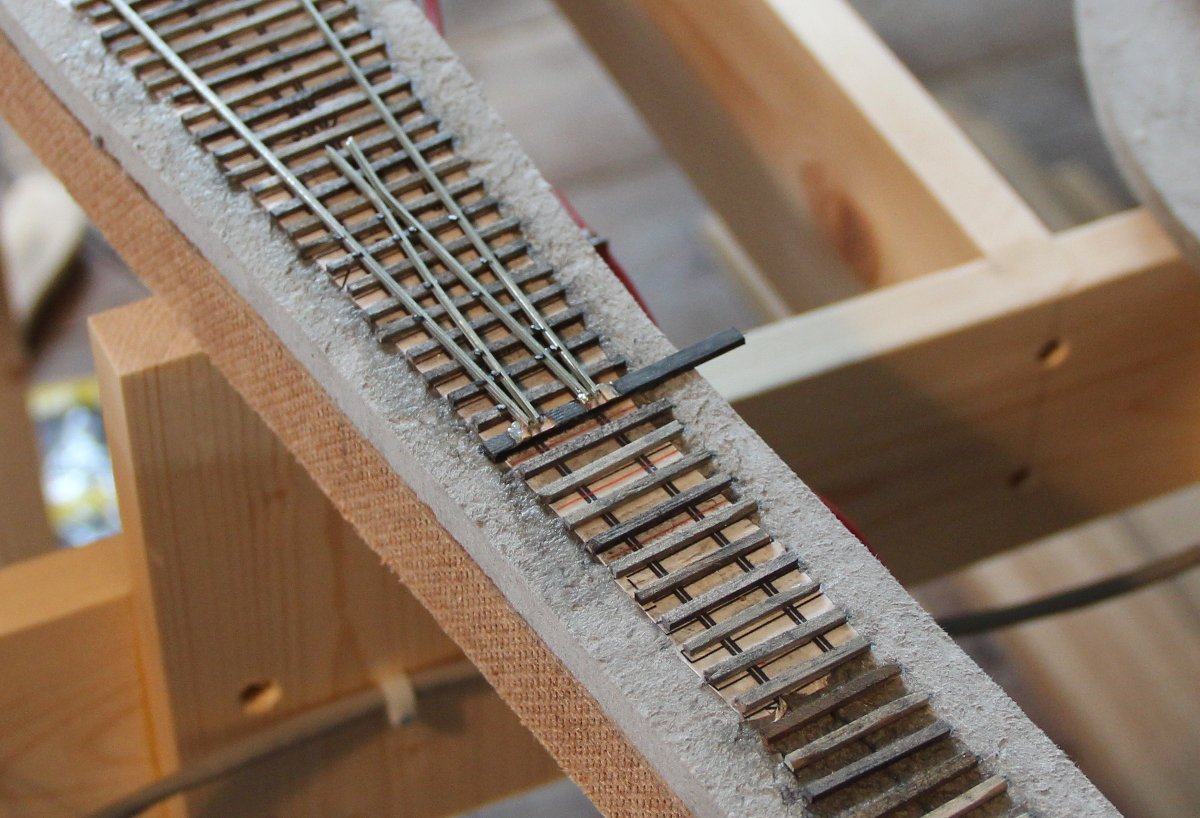 Rail is code 55. Headblock is a shortened S-scale standard gauge PC-board turnout tie (0.141" x 0.0625"). The copper had to be filed off the back to match the height of my Mt Albert wood ties. The outside stops are 0.5mm x 1.5mm brass soldered to the headblock. I'm going to try some NBW castings on top of the stops to match the prototype. Cheers, Jeff. |
|
Back to my bridle rods.
My first attempt to "dirt" them involved painting the PC-board surface with thinned white glue, and then sprinkling them with genuine Boreas Pass dirt. Most of it just fell back off, perhaps because I didn't use any kind of wetting agent. But even where I got a decent layer, you could still see reflections from the bright solder underneath. So round two saw the PC-boards painted with a neutral sand colour (in enamel), and then the dirt sprinkled on while the paint was still wet. This got me a thicker layer, and also got rid of the glinting solder. I then painted a 0.025" styrene rod, and tried to use wicking CAA to glue them down. This resulted in a not very good "stick", and also darkened the dirt near where the glue was applied (which you can see on the throw bar). For the next two (the bridle rods), I used white glue applied with a toothpick, which worked much better (and allowed for less nerve-racking positioning). Finally, the sides of the rail joiners were striped: the neutral sand colour on the outside thirds, and black to match the bridle rods on the middle third: 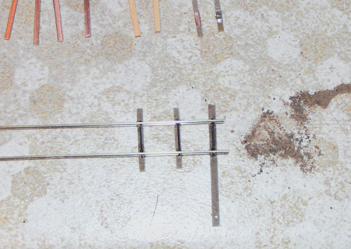 I'm quite happy with the way they look. Sadly, something went wrong in my soldering stage because they're all out of gauge by the same amount.  Hopefully their replacements will go quicker.... Hopefully their replacements will go quicker....
Cheers, Jeff. |
|
Dang Rail Craft/ME track gauges. I used them instead of my Railway Engineering "Rollee Holders" because I figured the heat wouldn't bother the Rail Craft/ME metal gauges, and it might or might not bother the Lucite rollee thingies. Sadly, the result is consistently over-gauge bridles.
I de-soldered one of the bad ones with my fingers on the rails to see how hot they get, and the answer is "not that hot". So I made up another one with the Rollee Holders, and its gauge is perfect. |
|
I trust you are running a truck through this to verify that the flanges clear those spiffy bridle rods?
Keith Hayes
Leadville in Sn3 |
|
Hi Keith,
The bridle rods are glued between the outside edges of the rail joiners, so in theory they should be clear. In practice, one did have to be trimmed because the positioning wasn’t 100%. (I have to run trucks through everything anyway because ME small spikes and code 55 rail are just *barely* compatible. I got one of MicroMark’s HO-scale inspection cars and replaced the trucks with Blackstone HOn3 arch-bar trucks. I might need to narrow the body of it a bit when it comes time to check scenery clearances. I suspect it would work equally well with Sn3 trucks under it….) Cheers, Jeff. |
|
Jeff, I would suggest you take a look at the etched spikes from Proto87Stores. For HO I would recommend the long HO spikes. If you want something a bit larger then the 150% HO spikes are good. These are the finest spikes made for smaller scales today IMHO. Best, Todd Ferguson Harrisburg, NC Sent from my Wacked and Cracked iPad III, OUCH!!!
|
|
I had the same trouble with the Proto87Stores spikes as the ME micro spikes: they pretty much require pre-drilling (or better spiking skills than I have). The ME small spikes I only bend about 1 out of 50.
|
|
FWIW, I have filed the heads of spikes to reduce their size and as a result their appearance and function. It takes time but if that's the only option it's worth it.
Lee Gustafson |
|
Having discovered that the 0.025" piano wire supplied with Tortoises is in no way able to throw a non-hinged switch, I've had to put the switch on the back-burner while I await larger piano wire.
So I went on to the switch stand. I'm using C&S Elliot stands that Rick Steele cast for me: 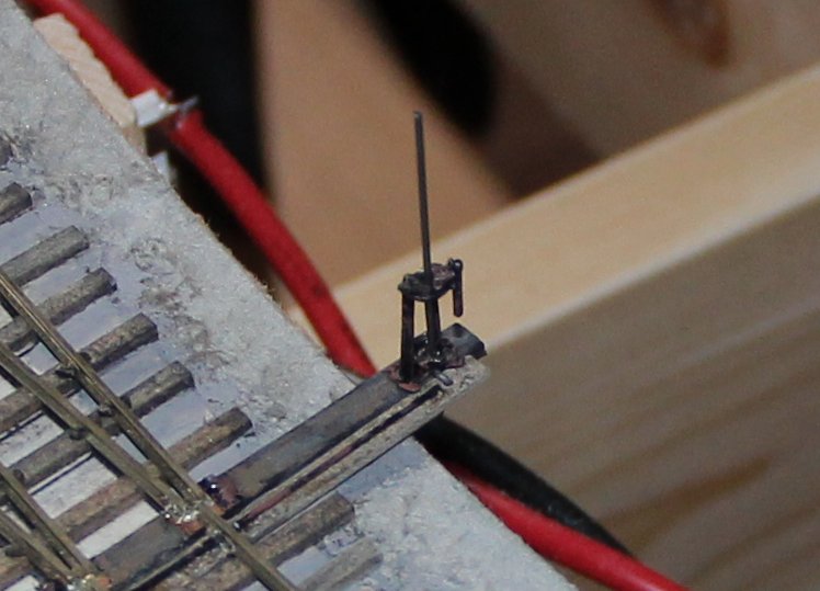 Getting the target to rotate in HOn3 scale is a tricky business. First off, there must be almost no slop in the holes you drill in the switch stand. 0.026" holes for 0.025" rod work well, 0.028" holes not so well. (You will have to file off any burrs/elongation from the end of the rod to get it through a 0.026" hole.) The crank offset is also critical. With a 1.6mm offset I wasn't getting much rotation of the target rod, while a 1.3mm offset gave me binding issues. 1.4mm gives me nearly 90° rotation of the target, so we'll have to call that good enough. 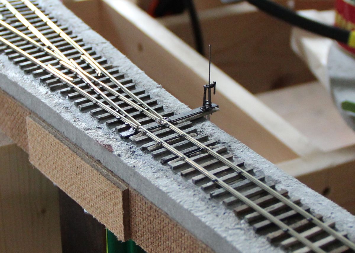  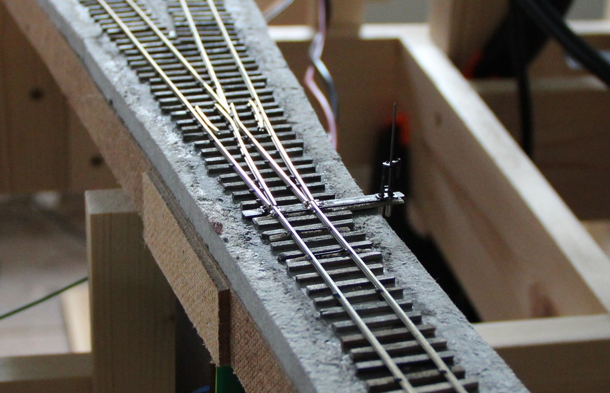 Cheers, Jeff. |
«
Return to C&Sng Discussion Forum
|
1 view|%1 views
| Free forum by Nabble | Edit this page |


