Flanger #015


Administrator
|
As you may recall, I started an On3 flanger last year which was to be more or less a duplication of a similar project I did in about 1985, which was more or less a more modernized duplication of a DSP&P flanger built by Paul Schenk from a Durango Press Flanger kit.
My original flanger was based on both the C&S Folio sheet and also a photo of flanger #015 which was published in both the Narrow Gauge Pictorial Volume VIII and the Pictorial Supplement. There were several things which I decided not to engage in the construction of that model to approximate #015, so I numbered that one #016, and eventually sold it to Rob Smith. This time I felt a stronger pull to more closely model along the lines of #015, especially as it was apparently the only flanger in use as a flanger at the time of the wreck on Boreas in January 1936. #013 had been converted to use as an Idler car in Leadville. Here is the well documented photo of #015: 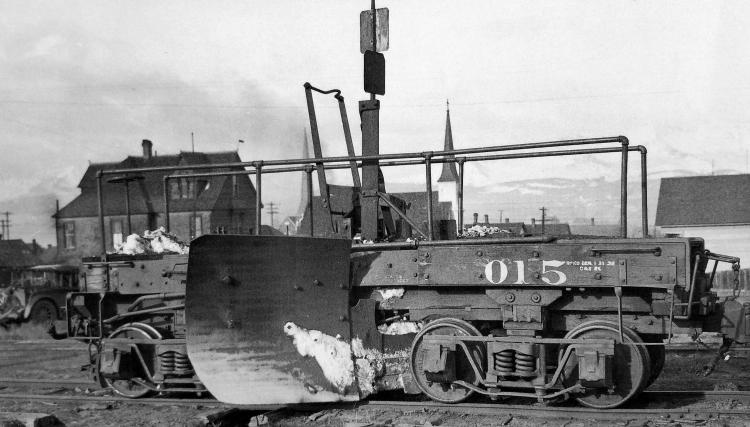 There are many things which are visible in this photo that are clear enough that it is like standing next to it in 1937. The heavy, layered and homemade looking blade, which had been added on to and enlarged more than once it it's life, and countless other things. One of the details that confounded me in 1985 has been resolved through study of this enlarged and photo enhanced version of the picture. That involves the peculiar aspect of the manual blade lever in the raised position, which should actually have lowered the blade, yet the blade is clearly raised well above the railhead. Look at this cropped version: 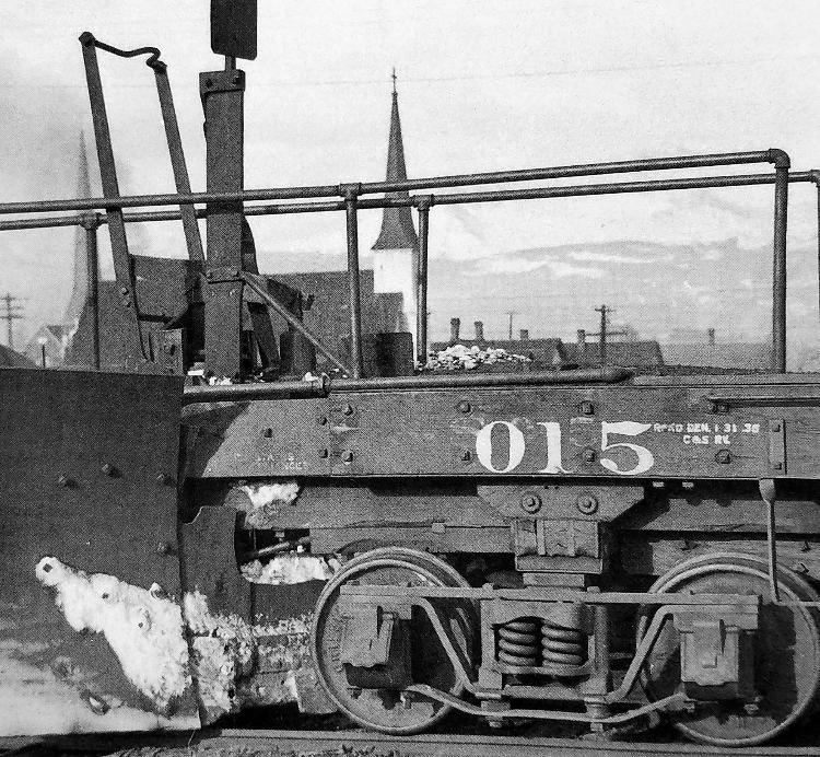 In this photo, you can clearly see that the boot at the bottom of the raised manual lever is bolted to the vertical steel blade support about three inches below a bolt that would clearly have been the location of the boot to be attached to lower the blade. In the lower position, the flanger blade would be low enough that it would have to be raised at grade crossings and turnouts. That the lever is attached in the manner which it is would allow the flanger to be used more as a spreader, pushing snow clear, as the wingspan of that blade is about 11' 6". With the lever in the raised position, bolted three inches below the "normal" blade support location, the flanger could have been easily operated in both freight and passenger service to keep the lne clear from drifts, without having had to continually raise and lower the blade. Almost all of the locomotives had Priest Flangers which were air operated, on the pilot trucks, and the large Butterfly style plows would have been effective clearing snow wide enough for the engine's cylinders, running gear and trucks to pass. Dragging the flanger behind would have added another 4' of width to the path, which would have been a great help in keeping the line clear. You see in the photo that the flanger mechanism has a vertical air cylinder, which the plumbing would have been apparently connected near the right rear step. The air fittings seem to have been removed, leaving only the trainline hoses on both ends. A couple of other details I found interesting are the traces of the original smaller "C&S 015" still visible behind the larger "015", and the reporting date on the brake cylinder repack "Repkd Den 1-31-36 C&S Ry", which was exactly 10 days after the wreck on Boreas when this flanger was coupled between #73 and #75. Or, is that "1-31-35"? I'm thinking '36 because there isn't any reason to imagine they would have repacked the brake cylinder in the middle of winter in '35. Progress on the model should be faster now, the frame and blade assembly are pretty much done. I'll send some pictures later, as progress continues. |
|
|
Mike,
Is it possible that the lifting mechanism has three positions the position in the picture which is the intermediate position, and a lower position and an upper position? The reason I ask is it appears in the photo that the blade extension might not clear the rail head in the position it's in as it travels thru a turnout or is it just the angle of the photo? Thanks for the photo and your observation of lifting level operation. Lee Gustafson |
|
Administrator
|
Hi Lee,
In all of the manual levers I've seen or studied, (this photo of 015 and various D&RGW flangers) there would only be two stops. One up, in which the lever rests solidly attached to the lift bars with the feet pressured flat at the bottom as the blade is lowered with the top of the rail just below the plane of the main blade, with the flangeway in place just inside the rail. This blade also drops on the outside of the rail outside and just below the railhead. That is why the blade would have to be raised at turnouts and grade crossings. The other position is with the lever locked flat into a bracket on the deck for that purpose. So the blade and the lever are either up or down. Normally if the lever is flat on the deck, the blade is raised. The only way the lever can be raised with the blade also raised is that it has been modified to do just what we see here, set to make it impossible for the blade to be lowered. We can see that the lever position has been modified when you see the bolt 3" above where the foot on the lever is attached. It is definitely obvious that 015 was used with the blade movable in previous times. It probably wasn't too hard to covert it back to operate normally by blocking the blade and resetting the manual arm in the lowered position against the deck. Once that was done, it could be operated manually without having to reconnect the air. The angle of the camera makes the blade hard to make out as you are looking straight on. One can see the angle of curvature in the shadow against the sills at the intermediate level of the blade. Otherwise you might have the impression that the blade is flat. This blade assembly is very similar to the width of D&RGW OI. Flanger OD is wider, with a wingspan of about 13'. |
|
Administrator
|
I have completed Car Flanger 015, and I am pretty happy with the results. Happy enough I don't want to build another one!
I'll get around to weathering it eventually, but I'm still waiting to get around to weathering rolling stock I built 30 years ago.... Pictures first.... 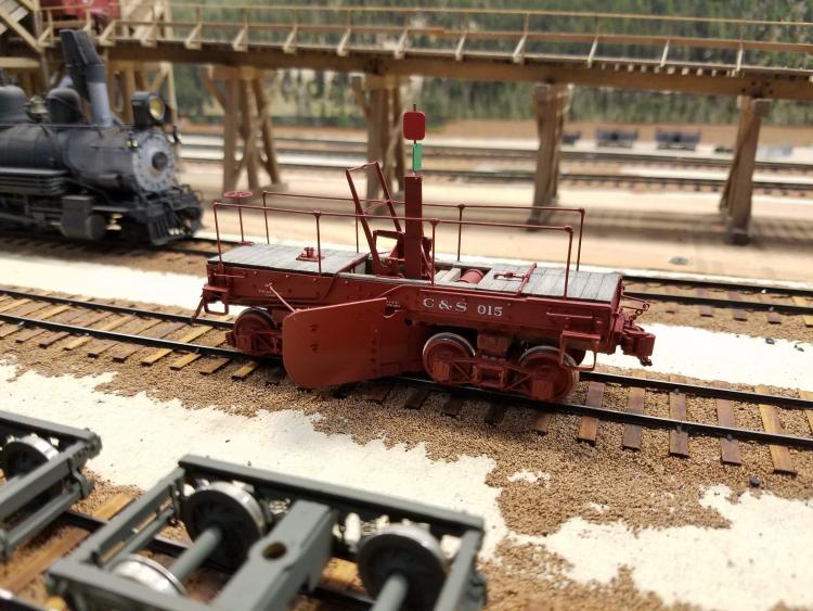  I began using a Wiseman reissue Durango Press RGS Flanger #01 kit, which was what I used to build #016 many years ago. From that kit I used some of the cast parts including the basic trucks and most of the lift mechanism. I also had an unbuilt San Juan Flanger kit, and that also provided several parts, including the basic blade and a few other details that I preferred over the recast Wiseman parts. Much of this model was scratchbuilt, including the body, and the patchwork quilt looking blade additions. The C&S Folio sheet provided basic dimensions, most of the rest of it came from staring at photos and a few conversations, including with Keith Hayes, who spotted some things I'd missed. Many weird things. The steps, fabricated outward with steel welded step plates, sheet iron sheathing over the side sills to the rear steps, and brackets fit over the front ends of the sills. I mentioned above (last year, was it? Seems like it...) the curious way that the hand lever was set in the lowered position despite the blade obviously sitting above rail height, indicating that it was used as a spreader more than as a flanger in the truest sense of the word. At least in later years. Now, having completed the model, I believe that the blade was modified for this use more than the mechanism was. It could still be raised either with air or through use of the manual lever, but as I indicated earlier, it could not be lowered further. Ice, rocks or possibly a high grade crossing might be why it would have to be occasionally raised, but it appears that even in the low position it should have cleared just about everything. Almost all of the locomotives had Priest Flangers, so the need to dig out the flangeways was redundant. At 13' span of the blades, they would have cleared out drifts well beyond the wedgeplows on the locomotives, which were only about 8' wide. This thing was probably used very frequently on Winter trains to keep drifts at bay in the high country, especially on the West End between Como and Leadville. There are even a few photos of them in use on the Passenger Train. I believe they were commonly used behind the road engine in regular use, and coupled between locomotives when running coupled downgrade as #75 and #73 were in 1936 when they were wrecked. Anyway, it was a lot of noodling and work to get here with it, but there it is.  One last thing for what it's worth, veteran C&S engineman Doug Schnarbush always referred to these as a "Car Flanger". |
|
|
Nicely done, Mike!
Cheers, Jeff. |
|
|
In reply to this post by Mike Trent
Mike, it turned out great! Did you take any photos of the process along the way? It would be great to see the sausage making.
Keith Hayes
Leadville in Sn3 |
«
Return to C&Sng Discussion Forum
|
1 view|%1 views
| Free forum by Nabble | Edit this page |