Class B4F in HOn3
12
12
|
Boy! I learned a lot doing these three. Not just about detailing and painting and stuff, but also about what my personal goals and likes and dislikes are in building models like these.
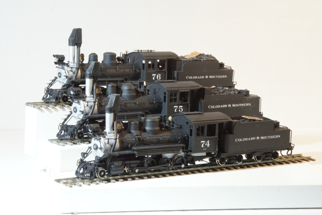 This project started with four HOn3 engines. They were a Westside #74 and two Westside #75s from the late 1970s and a hacked and broken Balboa #74 from the late 1960s that donated parts. I have often felt that the Westside 74/75 is one of the less appreciated and under priced C&S locos on the market today. It was one of the first with a good micromotor and proper gear train. I have always considered my #74 in particular to be one of my best running locomotives out of the box. In the last few years my urge has been to get these things out of the closet, off the shelf, and even though I don't have a layout, to make modern properly running model locomotives out of my dusty old collection of Brass. This means replacing motors and gear trains where needed, install DCC/Sound and LED headlights, and paint/letter them. I stop short of weathering as I have not (yet!?) developed the skills in that direction. So my engines are all freshly shopped. My last project, the #13 involved not only the basic "get-them-running" motor and DCC stuff, but also a lot of re-detailing moving the air tank and generator, new headlight, tender details, etc. This time I told myself that the goal was to handle obvious gross details that were obvious from 2-3 feet away but not to worry about the small bits. Thus, these will never win any contests, but they SHOULD look right running around a layout. Most of the details were OK. The biggest work was making one of the #75s into the #76 by replacing the #75's tender and domes with the tender and Brooks domes from the Balboa #74. The cab windows were modified on the #74 and #76 to remove the cross-sash windows installed by the RGS after the C&S days. I understand that Westside took these details from the #74 in the park in Boulder, but for C&S days the windows should have one vertical sash. The steam turrets between the generators and the cab are right. Half high on the #74 and full hight on the #75 and #76. The running boards are similar enough between the #75 and #76 that I left them alone as well. 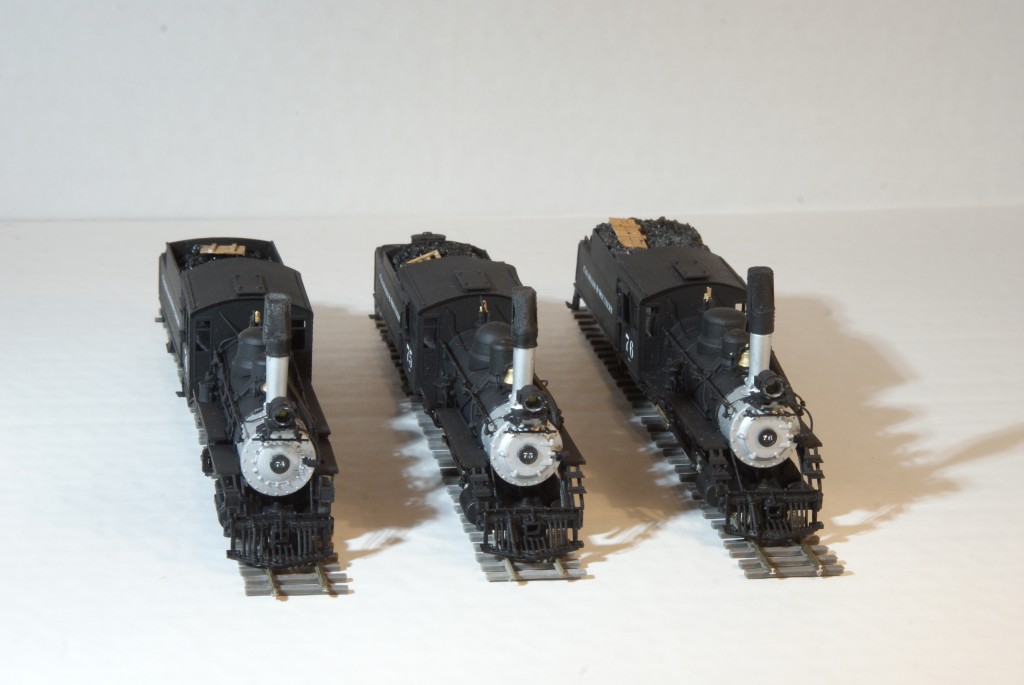 The Westside engines properly captured the different smokebox front of the #74 and the standard UP/C&S 6-lug smokebox front of the #75 and #76. The steps were also fairly right. I stopped short of finding gold lettering for the #75's number plate although I may re-do that and scribe to the brass on the outer ring at some point to properly model the #75s number plate. 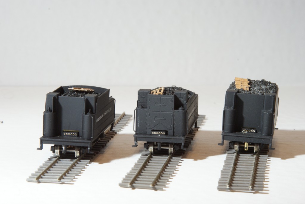 The tenders present some problems. First, the #75 has the lower side boards from it's diagnosed "top-heavy" roll-over tendency. However, the coal boards should be about a foot longer than the #74 and #76. It has the same 5' rear deck as the other two engines rather than the 4' that should be there. But my goal of "get them running" said that its not worth doing surgery on the tender. I notice it if I look, but it is sort of on the border line of being noticed at that 2-3 foot distance. A bigger problem is the donated Balboa #74 tender on the #76. Mike Trent and others have done amazing work in some other threads on the detail differences in the tenders. I was close to digging out the torch and turning the tool boxes on their sides, but again the tender is close enough to right that it doesn't really bother me. Finally, the tenders all suffer from Westside modeling the engine in the Boulder park. I understand that the RGS replaced the open coal bin and its system of wooden coal gates with steel doors. These three tenders all share that bit of design even though both the Westside and Balboa #74s are devoid of any coal gate door detail. I thought about opening the fronts of the coal bins, but on an HOn3 engine running up and down the test track one just can't really see any details under the cab roof. So my tenders have steel coal gate doors with wooden coal gates tossed up onto the coal load. Sigh... 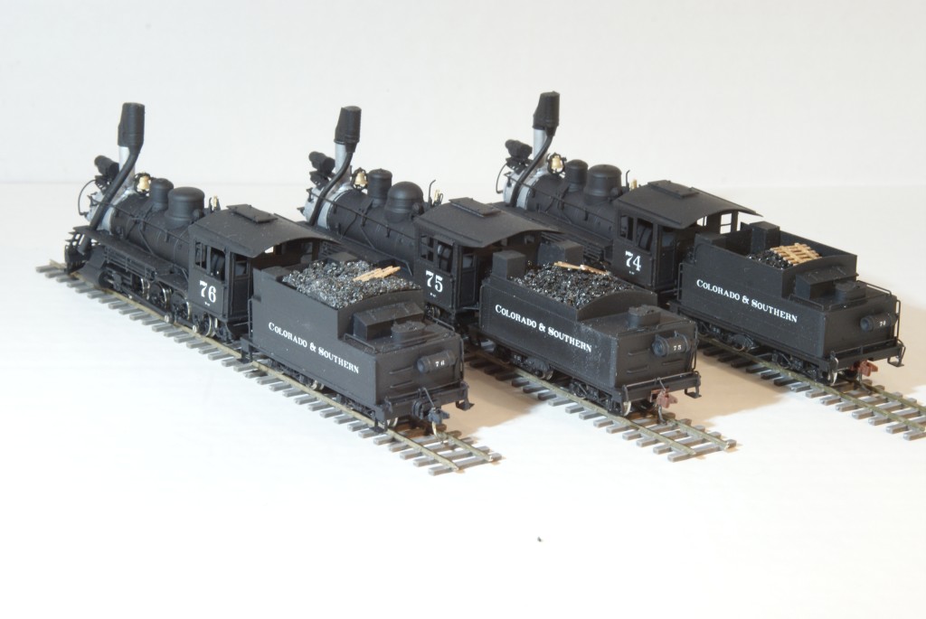 I did add the air reservoir to the back of the #75s tender and added double pipes to the #76. So much for my goal of not re-doing details on these three. But on balance, I think that the tenders are reasonable for HOn3 engines. 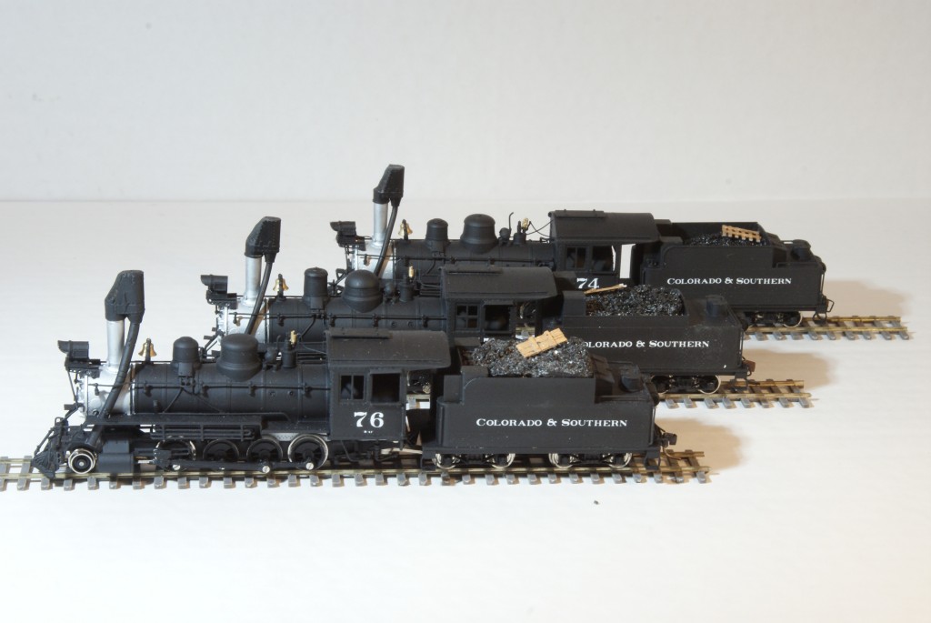 Despite all my disclaimers about not wanting to mess with minor boiler details, there is one nagging detail that has me bothered. I always felt the the #76 looked a little "cleaner" for some reason than her two sisters and I think that I know why now. On the #74 and #75 there is an air line that rolls over the rear of the smokebox going from the pump to the tank. On the #76 this air line is moved back a foot or two onto the first coarse of the boiler. With the pipe painted black (as it seems to be in all the pictures) it becomes quite noticeable there on the 76's smokebox. It just shouldn't be there and it looses the "clean" smokebox that gives the #76 a bit different feel. It is sort of funny that one bit of piping should stick out and bother me, but every other day or so I swear that I am going to strip the boiler, move that pipe back off of the smokebox, and repaint. Funny. So now my request. I've tried to give some of the trade-offs I made in these three models. I think that I have learned that I am at the stage where I really should be doing a bit more detail work. I really like my three sisters, but I also have learned that I am not quite satisfied with "get them running and don't bother with the little details." What details do you folks see that bother you? If you were to guide my hand on the next rebuild, what is the number one thing you would change? Don't worry about sounding critical. I love my three little engines and get a deep happiness seeing them huff and puff up and down my test track. But I also am curious about where my skills will grow and develop on my next project. Thanks for looking and thanks in advance for any comments. Skip Egdorf Los Alamos, NM
Skip Egdorf
|
|
Skip,
Beautiful work and a wonderful trio of B4F's. I've always been confused about the little window on the fireman's side of #74, was that a feature added by the RGS or was it present on the C&S #74? Sister engines #75 and #76 do not have that window, hence my confusion. You should be pleased with your work and stable of engines. Thanks for sharing. Lee Gustafson |
|
Outstanding!
|
|
Administrator
|
In reply to this post by Lee Gustafson
Lee, that little window allows the fireman to see the top of the stack from the rear of the cab. It is well known that #74 was not a popular engine among RGS crews. This was done because of complaints. The large double pane cab windows were, as I had been told, broken out with a brake club by enginemen in Durango because the older wood frames had swollen and would not slide open.
Skip, when I jumped into On3 and C&S (1980), the only two C&S engines that had ever been produced in that scale were #22 and (RGS)#74. I had the extraordinary opportunity to have unrestricted access to the #74 in Boulder which helped a lot in being able to measure any number of details and identify piping, etc. When it was completed, I sought two others for conversion to it's sister engines. At the time, the C&S narrow gauge was gaining a lot of interest thanks to Harry Brunk's series on the Clear Creek Branch. The more I learned about the C&S narrow gauge, the more I came to realize that the Clear Creek branch was different in almost every way from how mainline operations were run on the C&S. So, through the process of creating the other two B-4-F engines, the door opened for me to be able to actually portray mainline C&S operations with those big hogs which were too big to ever go any further than Golden on the Clear Creek Branch. So assembling my collection of "them Boulder engines" was a landmark moment in my C&S modeling career. Nice job! BTW, to represent the brass numerals on #75's number plate, I used decals from a C&S Passenger Car set, and they are perfect in not only size, but in font as well. One thing about those early HOn3 models was that #74 carried a 9 1/2 air pump as the larger 11" pump was removed during scrapping operations for RGS #42. That small pump was simply taken from a junk pile in Ridgway before the #74 was taken to Boulder. Your pics in this thread don't show the right side of the engines, and I can't recall if Westside corrected the pump or not. The Balboa engine for sure had a small pump. Anyway, you are off to a great start with these big hogs on your roster. |
|
Administrator
|
For further reading on these engines and their history:
http://riograndesouthern.com/RGSTechPages/rgstec7.htm |
|
Mike,
Thank you for the link. You're modest. You were a big part of #74's restoration and a historian of note as well as a major contributor of information for models of #74. Thank you for the information and hard work. I am going to re-read the #74 history several times as she was quite a boomer. It would be nice if she can be restored to steam at the museum or even the Loop. Again, thanks. Lee Gustafson |
|
In reply to this post by Mike Trent
Mike, Thanks for the comments. This was exactly the sort of thing that I had in mind when I posted the Pictures. The Balboa engine from the 60s did indeed have the smaller pump. 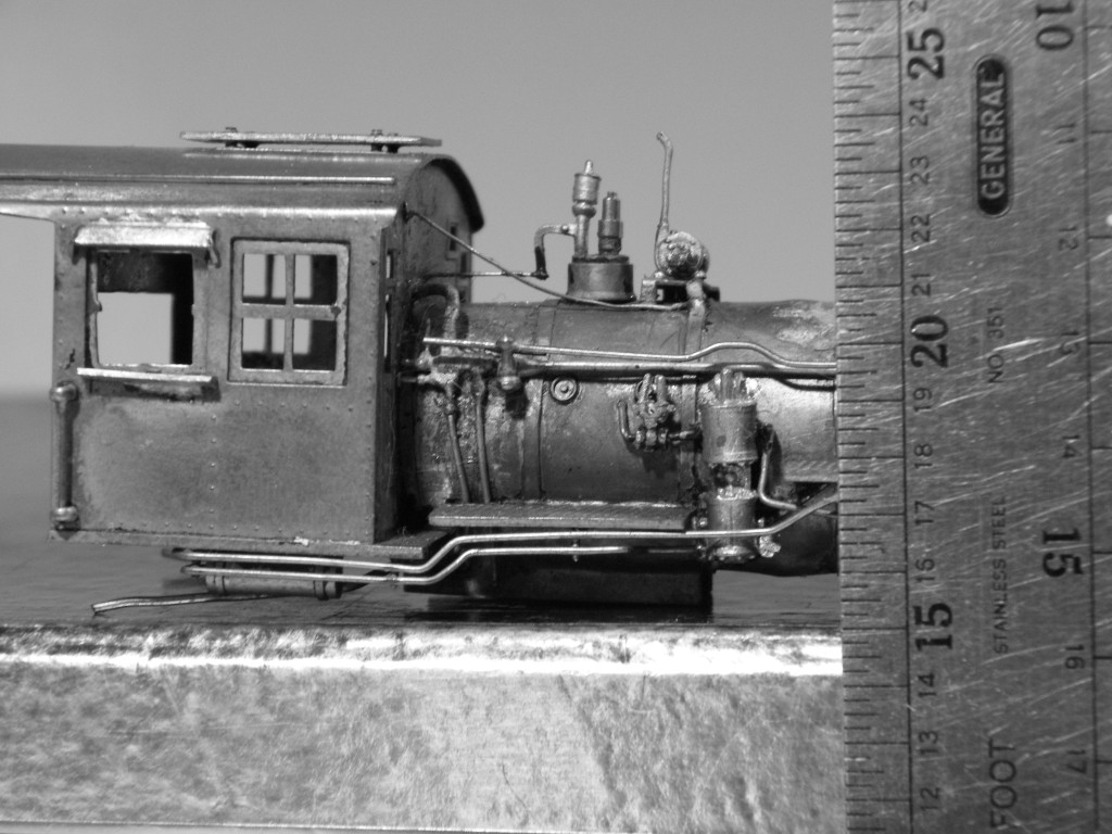 The Westside 74 and 75 both seem to use the same pump casting and it seems to be an 11". It is certainly larger than the Balboa casting. So that is one thing that I don't have to strip-paint and re-solder. 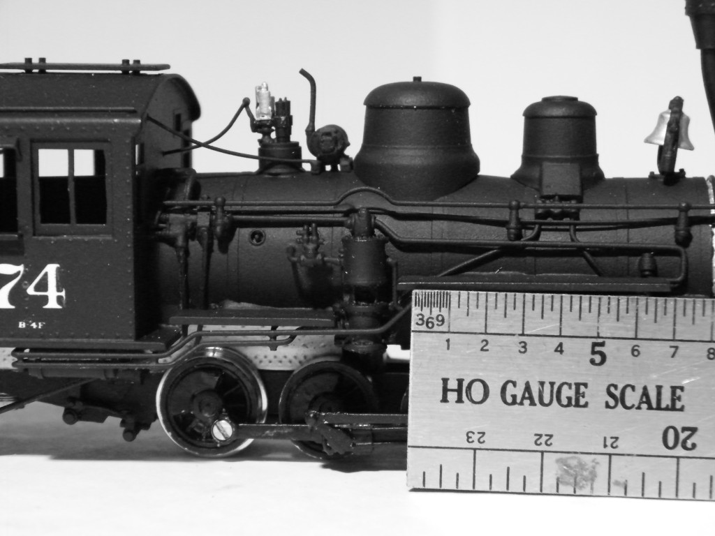 And here, for completness is the #74's right side in all her glory. Looking at the close-up photos makes me realize that I would like to figure out how to make a removable cab and put at least a few bits and pieces onto that naked boiler. OK, Deep breaths Skip. You have lots of other projects before redoing these three... 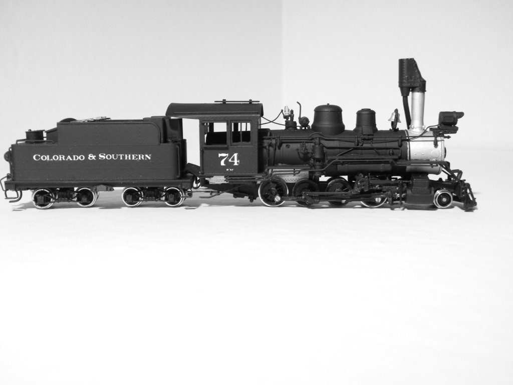
Skip Egdorf
|
|
Administrator
|
Hi Skip, yep, that looks like an 11" pump on your #74. Thanks for posting the picture of that Balboa engine. The guy who did the drawings for that project was a Boulder guy named Billy Bowen. He had gone down and measured and photographed the engine down in Central Park. I was, as I recall, just going into Boulder High School, that would have been the Fall of '66. Erick Nelson and I were in the same class, and were both members of the original Boulder Model Railroad Club, which actually had a layout in the basement of the Boulder Theater downtown. Billy Bowen was a member, but only an occasionally attending guy. One evening several of the members were at our basement and Billy showed up with the finished drawings of that #74 for Balboa. When he announced to the group that it would be produced in HOn3 I was as excited as I have ever been, and sure enough I got one for Christmas the following year, in '67. By then I already had one of the United 2-8-0's, and when I got that #74, I felt like I was really off to a great start. I guess I was, because I have spent a lot of years studying, researching, and modeling C&S equipment. Despite many and considerable distractions over the years, I've always "come back home" to the good old C&S, where my roots have always been.
One thing I might suggest, and this should be pretty easy, carefully take off that Whistle and armature complete with the rod to the cab from the Balboa engine and put it on your Westside. You can remove that one on the Westside with a Dremel, and don't worry about damaging it, it's now just a spare part. That one on the Balboa is exactly like #74's whistle and armature. The whistle is actually stamped #65, as I recall, but the one it had when #65 was still in service was just like it in pictures. Probably was the same one, it was likely swapped out during an overhaul somewhere along the way. The cab roofs are sort of a cross between the RGS extension which was bolted to the original roof to provide better protection to the fireman, and the original. But the trade off is that your tender is coupled a little further back than the prototype, so it probably looks better than it would if you cut it off. Besides, that would be a messy and probably fruitless task. The tender end beams evolved over the years. In years before '37, the rear beams were tapered, afterwards they were cut square. My #74 and #76 have squared beams, but #75 has a tapered beam as it would have had before the Como fire. You have that high round steam dome lid, so the square end beam would be just fine. That beam was probably replaced as it was being repaired after the fire. Anybody can find stuff to nitpick, but sometimes you just have to go by "feel" and follow Bob Stull's Rule #1, it's your railroad! Nice engines, Skip, they have the right family look. |
|
Administrator
|
Skip, another thing you can do to help out your coal gates, even though you have black painted brass in there now, you can still add for #75 and #76, three 2X6's (1X6's might be better, as you don't need them to be anything more than representative) across the lower part between the water legs, with a half length on the left side at the bottom. Just glue them to the front of those brass "doors". You can also add the upper gate if you choose. There was also a curved steel plate welded to the bottom of the water leg and the floor on the right (engineer's side) where the fireman could push his scoop against as he worked. That curved plate was probably about 8" high, and extended to the front of the water leg. Not enough to trip over, but just enough to push the scoop against. On one of the three, you might want to add the upper gate, so you can show how they were used.
Somewhere along the line, something must have happened to the cast bracket which held the upper 2X6 on one side of #74. We know this, because a picture or two of #74's upper gate shows that it was much longer, with two or three slats shorter in width so it could extend down to the 2nd 2X6. I've never seen another one that was like that, just another detail that made #74 different. The upper gates were normally only wide enough to reach between the boxes at the front, and the boxes usually left a couple of inches or so of a ledge so the upper gates could rest on them. That's why the lower slats of #74's upper gate were narrower. I don't know how the boxes were made on your engines, but it sure isn't worth wrecking what you have to fix them. I'm pretty sure I've posted how I made them, and the gates, for my engines. #76's boxes were completely different. They were a couple of inches shorter than the bunker sides, and were the full width of the water legs. We know this because the upper gate on #76 is both shorter in width and in height than the others, but that is also not worth fixing on your tender. It looks just fine as it is. If you add those lower coal retainers, you'll be surprised how good they look, because you can see them. You could also add 1X4's on the inside, opposite of where the one facing the cab is, to show how the gate looks at the top from the inside if the upper gate is in place. With some sooty black dust on top, the upper gate might look a little thick, but it still would look good. After that, make up a few fire tools to hang here and there, and maybe a water bag and you are ready to go. I have an extra scoop hanging on the side of #75's tender where one is pictured on the final run out of Denver in 1937. 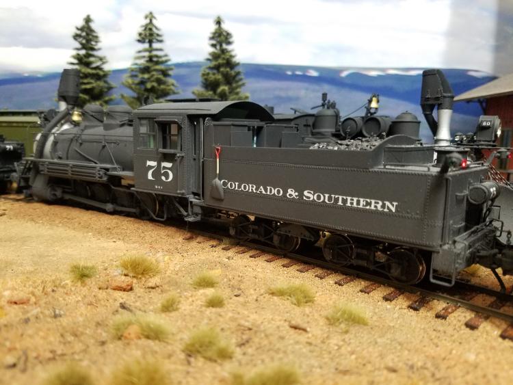
|
|
Administrator
|
In reply to this post by skip
Thanks Lee, for the comments.
Back in the late 70's and 80's, when I and others, mostly from the Boulder Model RR Club undertook our efforts with "Old No 30" in Central Park, we were mostly concerned about deterioration abatement as years of weather and neglect began to take a serious toll. Things led us to be able to play a big role in moving the train further away from Boulder Creek, and we were able to actually build new track for the train closer to the bandshell. One of our group, Mike Rowe, had an insatiable desire to one day restore the engine to operating condition, but most of us simply wanted to stabilize it as long as possible with the hope that the train could one day be properly and professionally preserved. That has happened, and we are all glad that both the locomotive and Coach #284 are displayed at the museum in Golden. But the locomotive already needs paint again, and the Museum probably doesn't have the means to undertake it's maintenance as it is still owned by the City of Boulder. So a similar effort may be necessary as was done earlier, to care for the engine, even if it means using mostly our own money as we did years ago. Over the winter, I will look into this, and we'll see if we can't get something organized to continue to preserve the locomotive so that it can be passed down to future generations without having to through any craziness, including begging for permission and money every time something needs to be done. |
|
In reply to this post by skip
Skip, great models.
Mike, thanks for all the back story. I had heard the RGS created the window so the fireman could see the stack: a clear stack was sign of good steam and the right fire. When PBL did their models, I never thought I would own all three myself. I started with the purchase of 75, which I selected because it seemed to me to be the shyest of the three. I now know why: 75 spent a lot of time in the shop. 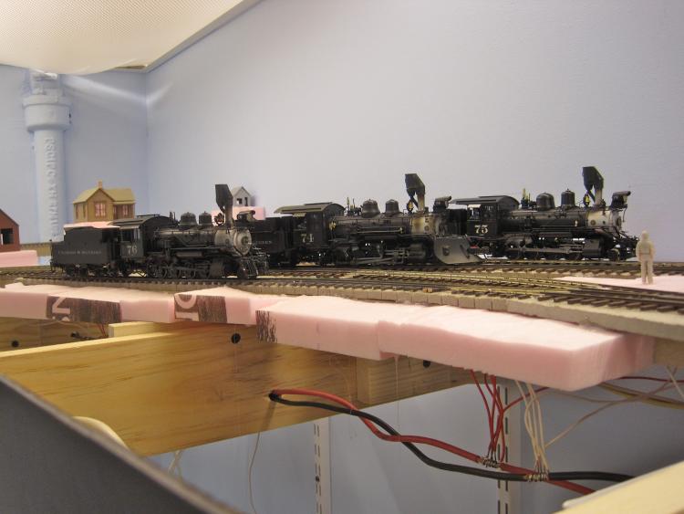 Through chance, the other two came my way. Shortly after the last one arrived, I took this portrait near Hemlock Street (then under construction). Some in these parts don't think of the B-4-Fs as true C&S locomotives. They were latecomers and lack the boiler mounted air tanks. But they were good haulers and anyone modeling the twilight of the South Park needs them as they were good for an extra carload on the 4%, and a lot more on the flats outside Denver. Now that I have 71 and 60 on the layout, it is true that they have more of the unique quirks that make a C&S engine. One detail I find fascinating is the C&S standard to place the air pump on the engineers side. This has the effect of creating a really complex look on this side of the engine, as it is where all the piping is (which is neat). The fireman's side (and view) is pretty clear, save for the ash tube. Evidently the DB&W (or perhaps Brooks) standard was to have the air pump on the fireman's side, and it was D&RGW practice too. In fact, I think most SG locos place the air pump on the fireman's side. I expect this is to provide a clear line of sight for the engineer? Why did 9th Street go so against the grain? I think the thing that bugs me the most about the models is the ash tube from the spark arrestor. On earlier locomotives, the C&S shops mounted the bell on top of the air tanks between the domes, and there is room between the stack and the dome for the ash tube to extend down and around the side of the boiler. On the Brooks' the bell is in the way, and none of the castings seem to get the look quite right to my eye. Maybe I need to study the prototype more closely? Mike can you please post a drawing or image of the lower coal boards and that piece of steel on the deck? I trust the steel was used to contain coal and scoop against. An interesting detail indeed.
Keith Hayes
Leadville in Sn3 |
|
Keith,
I doubt the airpump gets in the driver's line of sight, since the running board extends out to the smokebox front, that being the deciding factor. This wouldn't be any different to running longhood first in a Diesel. There is a picture in C&SNG taken from the gangway showing what I mean. Anyone riding and waving hand signals from the pilot will present outside the runningboard line and usually the driver will be looking out the cab side window. If seated and running out on the line, anything obscured by the runningboard is already mush. 
UpSideDownC
in New Zealand |
|
Administrator
|
In reply to this post by Keith Hayes
Hi Keith, actually, the practice of engineer side mounted air pumps goes all the way back to DSP&P days. So does the wood coal gates. What we refer to as "C&S" tender trucks go back to UP times on the UPD&G and DL&G.
The idea that the B-4-F class weren't true C&S engines is complete nonsense. None of the engines on any C&S narrow gauge roster were built for the C&S. Case closed, and isn't even worth arguing. It would be as pointless as the evolution from box headlights. No one says the B-3-C class weren't true C&S engines after they were rebuilt by the C&S. Well, the C&S shops also rebuilt and did all of the mechanical work on the Boulder engines before they were owned by the C&S and afterward as well. |
|
In reply to this post by skip
Keith ,
Part of the problem with the cinder catcher is that the down tube comes out of the bottom of the collector straight down . On the prototype the tube comes off at an angle above the boiler and then curves around the boiler. On all of the C&S models the down tube forces the Ridgeway Cinder collector to be mounted too high on the stack so it can be removed. If you look at a side view of 74,75,76 prototype photos the Cinder Catcher sits much lower in comparison to the sand dome just behind it . The routing of the down tube is a comprise at best and simply doesn't look right compared to photos of the prototypes. Charles McMillan |
|
This photo of my #537 shows the angle that I am talking about .
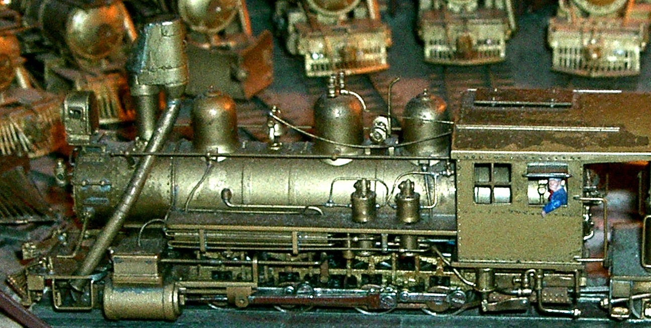 Charles McMillan |
|
Administrator
|
Nice job on the #537, Charles.
Keith, I think the diameter of the tube itself is somewhat undersized on the PBL models. The PBS castings I used on my big engines #74-#537) look to be about 9" in diameter. I don't have access to my Maxwell drawing he made from the C&S originals, so I can't provide anything else at the moment. |
|
In reply to this post by Keith Hayes
It's hard to find photos that show this area well. I think this photo from 1982 shows the piece of steel your'e referring to (it's just above the white baseball cap - Mike Trent seems to be staring at it as though he knows it will come up in future discussion): 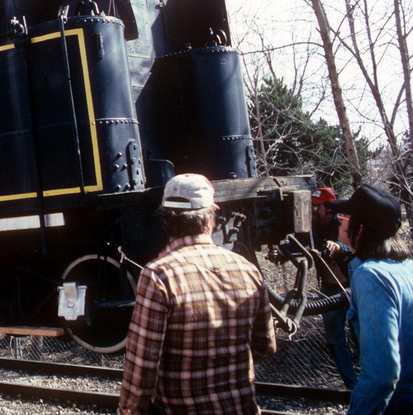 I don't have anything showing the lower coal boards, but this photo of #69 showing the wood coal grate that was typical of what was used on C&S narrow gauge locomotives may be of interest: 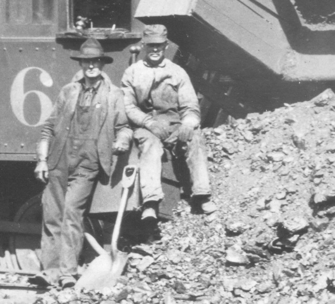
|
|
In reply to this post by Mike Trent
Keith, Mike, Not just the PBL, but the Westside tubes are undersized. If you look at several of the shots of my three in the original post, the #74 and #75 have obviously undersized tubes. You see when I got my second Westside 75 I wondered why I got such a tremendously good price. And why did the former owner give such a chortle while rubbing his hands together as he ran down the alleyway? Turns out that on examination for this project I noticed that the etching used for the collector had been turned upside down when cut out. The hinges were on the top, sliced crookedly where the screen met them... QA in Japan must have been a little lax that day and the first owner found a rube with some cash in his pocket to fix his mistake. In any case, I had one of Precision Scale's casting sets on the shelf and swapped them. The Precision unit has a much more proper tube size to my eyes. I probably should have swapped out all three. Skip Egdorf
Skip Egdorf
|
|
In reply to this post by Todd Hackett
Todd,
is this plate on #60? I wonder if it was for the Water Barrel to keep it clear of blows from the scoop? As per Rick Steele's post here http://c-sng-discussion-forum.41377.n7.nabble.com/Love-me-tender-With-apologies-to-Elvis-tp499p570.html
UpSideDownC
in New Zealand |
|
In reply to this post by Charles McMillan
Charles, You're right about that. The Westside engines shared this problem. The tubes exited the collector straight down. I spent some time trying to get the exit angle a bit better and the corkscrew straightened out to a bit more prototypical form. My problem is that, like you, to me the stacks just look too high for some reason. I think that I have measured mine and have them reasonably correct in height when I actually measure and compare to the prototype photos. But my stacks still LOOK to high to me for some reason. Haven't puzzled it out yet. Skip Egdorf
Skip Egdorf
|
«
Return to C&Sng Discussion Forum
|
1 view|%1 views
| Free forum by Nabble | Edit this page |

