C&S Boxcar Questions
12


12
|
Hi Everyone,
I have a couple questions about the C&S Boxcars that I think people here will have the answers to. - We have all heard the different boxcars referred to as "Phase 1 and 2 and 3". Now is the correct term "Phase" or is it "Type" as in "Type 1" and "Type 2"?? or is it "Phase 1" etc.??? - I'm assuming these Type/Phase terms were created by the railfan/modeler community and NOT by the C&S themselves. Is this correct? If so, did the C&S use any terms to describe the different car?? or did they just use car number blocks?? - Does anyone here have any good drawings and/or pictures of the cast steel car bolsters that were used on a Type 2 car?? Thank you all for the help. |
|
This post was updated on .
Hey Tim.
The "phase designation'" was invented by Harry Brunk in his NG&SL Gazette articles to describe the visual differences in the C&S boxcar fleet. Derrell Poole suggested that a more accurate scheme would be to list them by builder, year(s) of build and source of major hardware (trucks, bolsters, roofs, etc). To combine the two, "modern" C&S boxcars can be described as: 1898-1899, St Charles built, St Charles arch bar trucks, plate bolsters, wood frame / truss rods, wood roof with inside metal Murphy roof (Phase 0). 1907, C&S built, AS&F arch bar trucks, AS&F bolsters, wood frame / truss rods, wood roof with inside metal Murphy roof (Phase 1). Essentially, these were C&S copies of the St Charles boxcars, using purchased AS&F hardware, as first used on the 1902 coal cars). 1907-1908, C&S built, Bettendorf trucks, Bettendorf cast bolsters, wood frame / truss rods, outside metal roof with 13 ribs and small retaining tabs. (Phase 2). 1909-1910, C&S built, Bettendorf trucks, Bettendorf bolsters, Bettendorf steel underframe, outside metal roof with 13 ribs and small retaining tabs. (Phase 3). This 2015 thread has losts of discussion and photos of the C&S boxcar fleet: http://c-sng-discussion-forum.41377.n7.nabble.com/How-long-did-C-amp-S-boxcars-stay-in-service-td3293.html#a7473 The Bettendorf bolsters on the Phase 2 boxcars were the same as on the Phase 3, SUF boxcars. Bob Stears drew plans recently published in the Gazette--Jan/Feb 2019, pages 50 and 51. You didn't state what scale you are model building in. Styrene kits are available for the Phase 2 boxcars in both Sn3 and On3. HOn3 cars could be kit-bashed from the Grandt (now San Juan) Phase 3 SUF kit.
Jim Courtney
Poulsbo, WA |
|
So, what you're saying is, this "Phase 1-2-3" business is actually Brunkspeak ?
"Duty above all else except Honor"
|
Yep. My little bit of Brunkdom are these Elliot switchstands Rick cast for me from Brunk molds: 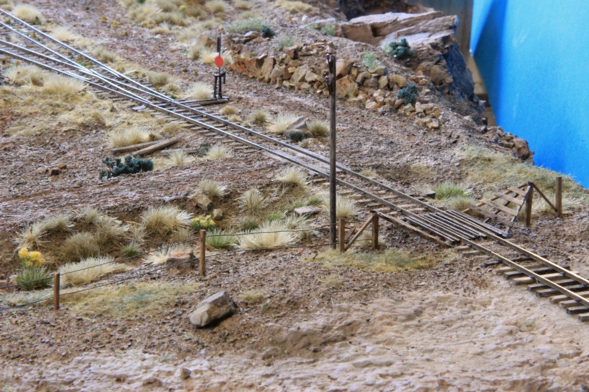
|
|
I will go on record that the bolsters between phase 2 and phase 3 boxcars are not the same. the bolsters for the phase 2 cars include truss rod supports, while the phase 3 cars are an all steel under frame and have no truss rods. I have not seen photos of the phase 2 bolster, but Derrell detailed this including a drawing in fine scale railroader magazine several years ago (I do not have the date handy but it has been posted before.
Al P. |
|
In reply to this post by Jim Courtney
We've been Brunked!
(Jim, I think Tim models at 1:1). 
Keith Hayes
Leadville in Sn3 |
|
"My little bit of Brunkdom are these Elliot switchstands Rick cast for me from Brunk molds"
===================================== As usual, your work is Brunktastic ! Even the Brunkmeister himself would be impressed.
"Duty above all else except Honor"
|
|
In reply to this post by South Park
Tim is "Modeling" in 1:1 scale as Vice President of the South Park Rail Society in Como. We have a couple"Kits" arriving soon that need a few parts. More on them shortly :)
Jerry |
|
Yes; Keith and Jerry are correct. We have some interesting projects coming up in Como that require us to complete our research on the type 2 boxcars. We don't have good drawings of the type 2 cast steel bolsters but it looks like the CRRM may have them on file.
Since we can't find any surviving type 2 bolsters it looks like we will need to make them. The current debate is if we should cast them like the originals or fabricated them like the Friends of the C&TS did with their "Wing" bolsters for their passenger car projects. Either way, detailed drawing are needed. I had heard that the H beam bolster used on the type 3 was also used on a type 2. I didn't think this was correct but I have only been researching these cars for a few months now so I thought I would check in with you guys that have been doing C&S research for years. Like Jerry said, we will have more about this project out shortly but suggestions on doing a restoration "correctly" are always welcome from the people here. In my experience, the modelers pay a lot of attention to the details and to do a prototype restoration correctly, we need a few "rivet counters" to help guide us in the correct direction and to complete the best restoration we can. |
|
In reply to this post by Jeff Young
Are these static or does the target rod rotate? I had static APAG cast white metal harp stands to dress up the stub turnouts on my On3 Alpine Tunnel layout. Fascia mounted rotary switches ala an MR article moved the stubs and powered the frogs. First open house for Mid Atlantic NG group a guest handed me one of the harp stands and said this one isn't working. Another attendee rotated the rotary switch and destroyed the mechanical stops and wiped the 12 position rotary around the clock - the joys of an open house. Bill Uffelman
|
|
Target rod rotates.
I’ve been lucky so far with visitors (other than the top of a tree). I’ll keep my fingers crossed. ;) |
|
Lucky man - or more sophisticated visitors.😁😁😁
|
Re: C&S Boxcar Questions -- Phase 2.5 Reefers of 1909
|
This post was updated on .
In reply to this post by Al Pomeroy
Al is of course, correct.
The Bettendorf bolsters on the "phase 2" boxcars of late 1907 to 1908 differed from the subsequent bolsters as a part of the Bettendorf underframe "kit" that was applied to all subsequent freight cars, beginning in early 1909 with the reefers. Not only did they have attachments to accommodate truss rods, but the attachments to the side and center sills also had to differ; the phase 2 boxcars had 9" tall side and center sills, while the phase 3 SUF cars had shorter 7" side sills, the center sills replaced with a steel I-beam. I looked through my files for any good drawings of the phase 2 Bettendorf bolsters -- no luck, nada. But, I did run across this C&S oddity that might help. I realized that this little C&S factoid has never been posted here. Years ago, I purchased all the C&S related drawings that the late John Maxwell then offered . . . 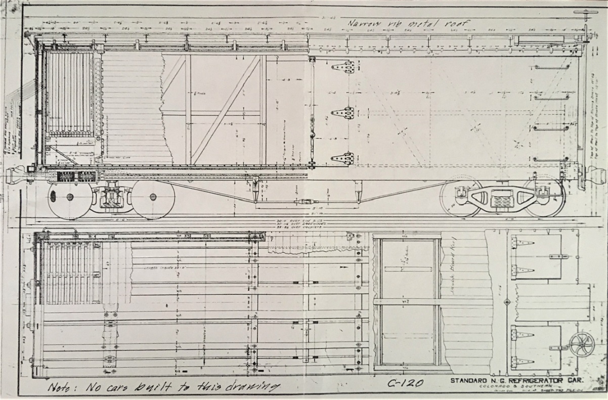 This the C&S Car Department's drawing for the new reefers to be constructed in 1908-1909. The date at the bottom right is barely legible, but seems to be "11-xx-07". As originally planned the modern reefers were to be companions to the "phase 2" boxcars, with wood underframe, truss rods, Bettendorf bolsters and trucks, the same coupler striker plates as used on the phase 2 coal cars (1907) and late batch of phase 2 boxcars (1908). The reefers were also to have the same 13-rib outside metal roofs as the phase 2 boxcars. Evidently, by late 1908, with the car building program going full steam, the C&S became so enamored with the new Bettendorf products that they went full in and began applying the new steel underframe to all subsequent cars built. Thus, the reefers represent an intermediate phase of the switch to the new Bettendorf steel underframes. They required shorter side sills of 7" height vs 9" height on the truss rod cars. But to retain the use of the phase 2 striker plates (maybe they still had 20 or so on hand), the end beams had to be 9' tall. This explains why the bottom of the sides are 2" higher above the rail than the bottom of the ends. It required those odd corner irons with the angled lower corners on the outside of the side mount, to transition up 2" from end to side. For what ever reason, the reefers actually built and delivered in early 1909 reverted to a inside metal roof with outside wood sheathing. Perhaps perforating the new outside metal roof with the four ice hatches presented problems?? Anyways, the above drawings does include details as to the phase 2 Bettendorf bolster in cut a-ways: 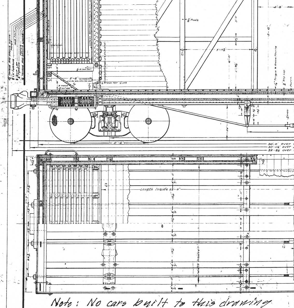 And here is the original end drawing, modified to show the application of the new steel underframe as well as the outside sheathed metal roof: 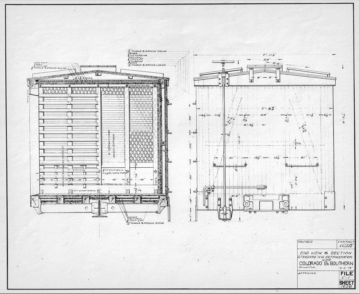 The original 1907-1908 cast striker plates were retained for the reefers of 1909, replaced with new cast striker plates of two designs on the 1909-1910 boxcars, stock cars and coal cars. Note the 4 board roof walk, typical of the new cars of the first decade.
Jim Courtney
Poulsbo, WA |
Re: C&S Boxcar Questions -- Phase 2 Bettendorf Bolsters
|
I finally found drawings of the Phase 2 Bettendorf (BAC) bolsters.
The drawings were traced from original C&S erection drawings by Derrell Poole and published in the Feb/Mar 1995 issue of Outdoor Railroader. As the drawings are copyrighted by Derrell I don't think it appropriate to scan and post here. Tim can email me if he'd like a copy.
Jim Courtney
Poulsbo, WA |
|
In reply to this post by Jim Courtney
Thanks Jim. I guess that settles the question about the Phase 2 bolsters being the same as the phase 3s. They are not the same. The drawing doesn't show the phase 2 bolster in much detail but it does show enough to confirm they are different then these Type 3s.

|
Re: C&S Boxcar Questions -- Phase 2.5 Reefers of 1909
|
Tim,
if you do find the real drawings at CRRM, please advise how others can get a copy of same from them. often times they have items of interest, but are sometimes hard to find due to the description assigned in the data base. the other though was that I could offer cad services for the manufacture of the new bolsters. I recently did a drawing package for a centerplate that had cracked in service. 3d cad was generated, followed with 2d drawing, documented several manufacturing options, alongside the original design. Al P. |
|
For those who may be interested, some more details on the new "Type 2" boxcar restoration project has been posted on the NGDF post.
The South Park Rail Society has teamed up with the Narrow Gauge Preservation Foundation to bring the only two surviving "Type 2" C&S boxcars that we know of back to Como. The Narrow Gauge Preservation Foundation has generously awarded the SPRS a matching grant of $10,000.00 This means your donation to this project will be doubled! So now your $100 donation means $200 will be going towards the project. I would also like to Thank the members of this board who have already helped with the research needed to restore this C&S boxcar correctly. Direct Link to Project Page |
Re: C&S Boxcar Questions -- Phase 2.5 Reefers of 1909
|
I hope this time you'll be lettering the boxcars correctly not like that "LGB" rendition done on the #8027.
UpSideDownC
in New Zealand |
Re: C&S Boxcar Questions -- Phase 2.5 Reefers of 1909
|
Chris,
While i don't know where Jason received his information concerning the 8027's current paint scheme I doubt it was LGB :) what would be the most appropriate scheme for the 8027 ? Jerry |
Re: C&S Boxcar Questions -- Phase 2.5 Reefers of 1909
|
Jerry,
thanks for your reply, I haven't brought this up since the majority of NGDF readers are not exactly interested in the C&S and reflect such. I also have great respect for what Jason does, and has done, even if he has erred badly with the lettering. Do not get me wrong on that score. I am aware it would be a lot of dollars to correct some of the hardware errors such as finding full airbrake components, seating the truss rods against the Queenposts or adding the missing corner plates, positioning the mid-carbody Grabiron's upside down as it should be per C&S practise. The jury is still out in my mind as to the roof, the C&S did redo some rooves with metal that looks like corrugated iron in several photos. Jason's comments seemed to give me the impression he believes it was added after railway use. As for the lettering, the Button scheme is correct unless you wish to display an earlier time period such as the Block or earlier Script, but there are a number of glaringly obvious errors in Jason's rendition. This car sits as your centre piece for all the public to see. The &S above the road number has been done in the extended font found on Locomotives, Rotary and Passenger cars not freight stock. The data appears to be from the photograph too large and widely spaced out. I've never seen any C&S boxcar with the LENGTH data encroaching the Doorstop castings as portrayed on the #8027. To me it looks like the data is 4" when it should be 3" or later post-1935 some received the 2" Data often referred to as the Leadville scheme. Some cars got in the 1930's a DEN WT in 4" added, an employee shortcut I presume, since there aren't many showing in photos of the period, but at least enough done that way to get two coupled together in one shot. 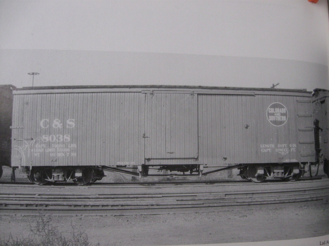 Lad Arend Photo: Narrow Gauge Pictorial volume viii pg30 This photo shows the proper lettering inc the Den Wt even though it is applied to a Phase 2 car, remember that Button paint scheme was applied after all phases were constructed and in service, the repaints didn't vary in application to different Ph. Boxcars like it did on the Coalcars. 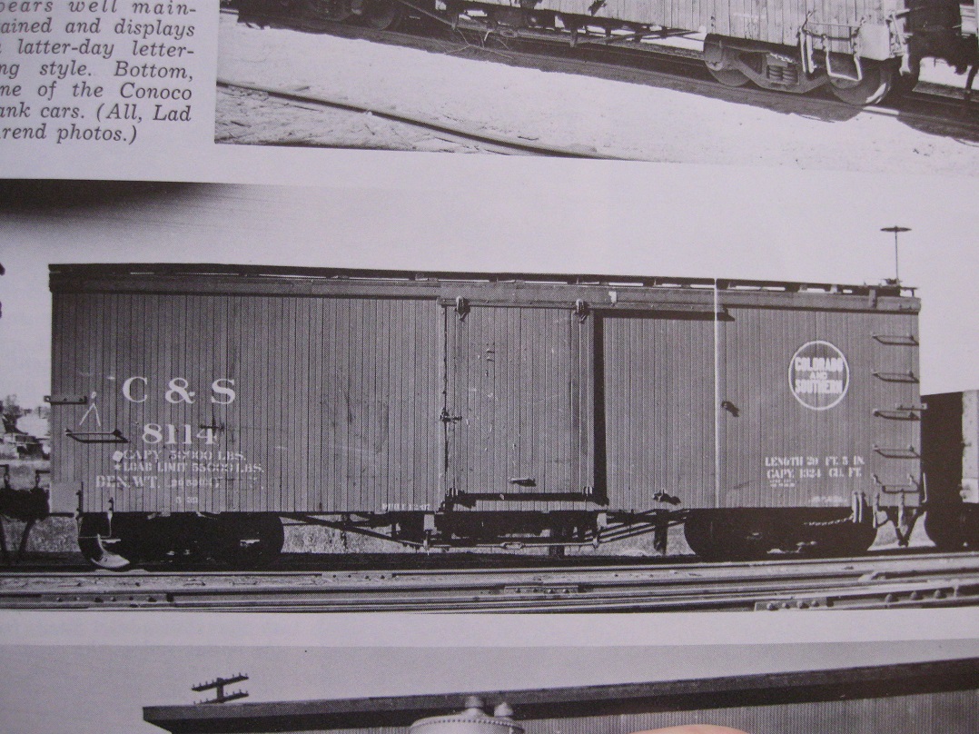 Lad Arend Photo: CRRA#12 South Park Line pg189 FWIW You aren't alone is having lettering errors either! It seems to proliferate in the recent narrow gauge restoration attempts.
UpSideDownC
in New Zealand |
«
Return to C&Sng Discussion Forum
|
1 view|%1 views
| Free forum by Nabble | Edit this page |


