Building Leadville Designs Coal Car / Flat Car / Cinder Car Kits in C&Sn3
Building Leadville Designs Coal Car / Flat Car / Cinder Car Kits in C&Sn3
|
Since folks have been receiving their Leadville Designs kits this past week, I thought we should have a new thread for construction of these guys.
I've looked through the kits and have started a-building 4 cars (making it 4 times as likely that I'll never finish). Mike McKenzie, on the other thread, asked about trucks: The 1898 St. Charles coal cars used the St Charles rigid/trussed 4' wheel base trucks, formerly offered by Cimarron Works in Sn3. The 1902 C&S built copies used ASF 4' wheel base trucks on ASF cast bolsters, these were also offered by Cimarron Works. The Cinder Cars were converted from St. Charles coal cars in 1904, numbered 0100-0108, so would have used the St. Charles trucks. An additional cinder car was constructed in 1909 from a Peninsular 30' coal car (4786) and was numbered 0109. It would have used the so-called type "B" 20 ton truck, offered by Leadville Shops in brass. I'll post some photos of the trucks that I'm using in a day or so. Having looked through the kit, it looks like you 1920s - 1930s C&S folks are in luck, as Bill has burned grab iron holes for all the USSA grab irons. DISCLAIMER: Let's get this out of the way. Probably 99% of the folks building this kit model the C&S the 1930s. I only know of 3 people who build C&S stuff in the first decade. Besides myself there is Steve Guty, working in HOn3, and Geoff Hamway working in Sn3 (true, Geoff models the RGS in 1905, but has been known to build a C&S freight car or two). I purchased 6 kits to build up: 1. An as built 1898 St. Charles coal car for my 1901 roster. 2. Three as-built 1902 C&S built coal cars, and 3. Two as-built 1902 flat cars, the coal cars and flat cars for my 1909 roster. I will likely deviate from the kit design significantly, substituting some parts, fabricating other parts. All those laser burned grab iron holes are a problem for me. More to follow in the next couple of days Please feel free to post photos and questions of the construction of your kits here as well.
Jim Courtney
Poulsbo, WA |
Re: Building Leadville Designs Coal Car / Flat Car / Cinder Car Kits in C&Sn3
|
Administrator
|
This post was updated on .
Well Jim, it's not one of these nice new kits. But for inspiration, here are some pictures of an Sn3 cinder car scratch-built by the late great James Finnell. Mind you, this car was probably built 40 years ago and can still hold its own. It's one of the few pieces I've kept in my collection. I will enjoy watching your progress. Good luck with your builds!
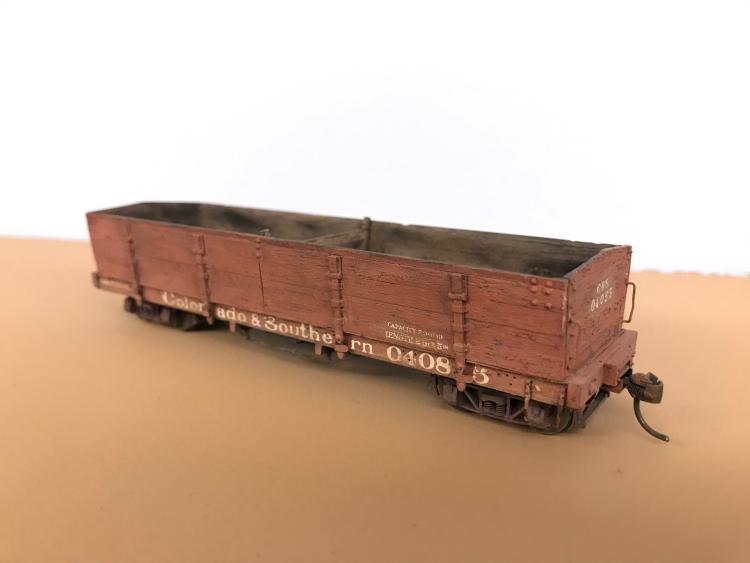 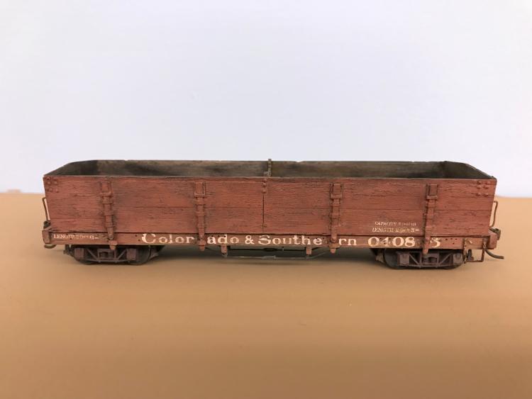 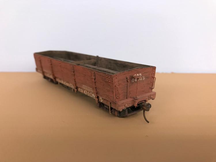 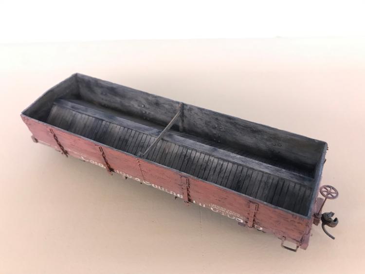 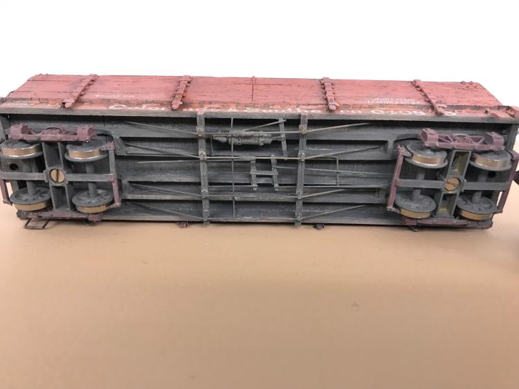 |
Re: Building Leadville Designs Coal Car / Flat Car / Cinder Car Kits in C&Sn3
|
This post was updated on .
Inspiring photos, Darel!
I started working on the Leadville Designs coal and flat car kits about a week ago, finally enough to begin sharing. First, some tools that I now consider essentials, in addition to the usual modeling tools (knives, drills, tweezers, etc.):  Clockwise from top: JLC razor saw and miter boxes; Mini-architects scales, Skinny fiberglass eraser, Pocket machinist's rule. JLC Razor Saw: A very thin (0.005" thick) blade with tiny teeth on one side, very tiny teeth on the other with wood handle (https://umm-usa.com/onlinestore/product_info.php?products_id=35&osCsid=a0ed3cd1dd5066706b1694627e236860, extra blades also available https://umm-usa.com/onlinestore/product_info.php?products_id=50&osCsid=a0ed3cd1dd5066706b1694627e236860. A great little saw for cutting wood, styrene and brass. A micro miter box set is also essential: https://umm-usa.com/onlinestore/product_info.php?cPath=21_28&products_id=8706&osCsid=a0ed3cd1dd5066706b1694627e236860. With the razor saw and miter boxes one can cut stripwood and Evergreen styrene strip and achieve precise cuts that are square in two dimensions, through the width of the strip and the depth of the cut. The adjustable stops on the micro miter boxes allow multiple, identical parts to be cut. Mini-Architects Scale Rules: Transferring dimensions from 1/4" scale plans to S scale models can be tedious. I've been using an architect's scale for decades (3/16" scale is one twist from 1/4" scale). With these little guys, I no longer knock things (like open bottles of paint) off the workbench with the free end of a 12" rule. https://www.amazon.com/Mr-Architectural-Pocket-Engineer-Engineers/dp/B0885RP8PK/ref=sr_1_3?crid=245EF846VSTB7&dib=eyJ2IjoiMSJ9.LTMYU8ASTxy_EX6tKv1dtOTzwbSXlYm1LmEmH3ibbeKC3iu_Ej9APjqhDJgvUfHtkjQCTgrKkWfbsfA8D9rwweoXpPOQgAdfEl3Q4ruIUohbMM_j0VHHGrhnTWmSYJ1B9mPuknx-uLRTIP2hwWC8UzTagCYuSIybx8-pZm0OzzExgGH_D8BU40i2mett9SV3bk4XuzGcVuf5s3QuO66GHfajtf3-CiKreXIlJXNXkdf53nVFp4bNISIm8WjrJq1WpMzH6X-TKV_WKi5L9QsZqiGf3yDf7hC_cD-up10XsJ8.B8pciK4vKo_Y3dEKsT03T_MWIMjLjZ8LFJV_ge5m7II&dib_tag=se&keywords=mini%2Barchitectural%2Bscale%2Bruler&qid=1722719646&sprefix=mini%2Barchitect%2Caps%2C182&sr=8-3&th=1 Skinny fiberglass eraser pen: Back in the 1990s, a Gazette article made "scratch weathering" popular. PBL marketed a fiber glass eraser brush for same. I could never get it to work until my friend Dale Kreutzer recommended this little guy. It is good for removing adhesive stains (MEK on styrene and ACC on wood). It is also very handy in cleaning up solder joints on brass assemblies. Brush: https://www.amazon.com/Extra-Fiberglass-Scratch-Brush-BRS-290-00/dp/B002RMCFZM/ref=sr_1_14?crid=1IFXYC55QV7HV&dib=eyJ2IjoiMSJ9.SMYcRl4yexvqcZodEra_oLxlmyWjxGaKbj-yX5NyOIBEFyIVhrtTxZoWy41bR6p44aCWwHXAD_exaDc81BHDuDsEg1NaJ7Vza0g7maF4gANehb26UcD0uvWLfzTZlv_Xdw7bEW0E7dXtcdlMOyDaMp_3AzjdvhptgT-ZytJDUqUzQqz5Fpg_0dkfkZtt-mhCvy41x8fAy-poS1c5DPEL6iKmfwbgkmsN08Fm3I91pDwW67mTMkXmZAisA0uBmBNpXsKqrpXS-fCowD5BkZW_wnxZnu5dt-X-BqZKhHNnGsM.fSsqekNCYLF_JHdZmAtpVDwOKbjm3QH4tYLaXq8gh_s&dib_tag=se&keywords=fibreglass+eraser&qid=1722719552&sprefix=fibreglass+eraser%2Caps%2C173&sr=8-14 Refills: https://www.amazon.com/Extra-Fiberglass-Scratch-Refills-BRS-290-01/dp/B002RMFOE6?psc=1&pd_rd_w=9JCmi&content-id=amzn1.sym.55c0153f-1fb7-42ff-8241-d1c0f3732289&pf_rd_p=55c0153f-1fb7-42ff-8241-d1c0f3732289&pf_rd_r=HYMTVQ1WN5WS60WR6RVN&pd_rd_wg=1ZKYp&pd_rd_r=c13a9135-fd0a-4f14-afcf-503ff93c8a16&ref_=sspa_dk_detail_img_1 Pocket machinists' rule: This little 6" rule has divisions of 1/32nd and 1/64th. Since S scale is 1/64"=1 scale inch, the little rule allows measuring in scale inches. The sliding pocket clip has a square upper edge, that can be used like a T-square, to lay out measures for grab iron hole locations from top or side edges. Also useful for measuring car frame height above the rail. https://www.amazon.com/General-Tools-300-Precision-Stainless/dp/B00004T7SW/ref=sr_1_2?crid=1ZH72OVLDVUZX&dib=eyJ2IjoiMSJ9.kkp_IIu6-cHfo0hjncHRG-pAVMrGz7oFzcuTrNetfeJKmuFMbx2hoJs5Tq4i2F9PF8aZ9DAvYGbYD4o65-e39BhlYlfYvNyoJgcX3DPpFy-EJk-Tvh8KBp3WSfbPCQTqDmyR_sfSFKbJM7XRg8BRxerPd7baVM2U3I_Xcrr_Xx1AeXOs-ia9IPs3aTK1y70RKP6ib58GBs0pWSHRfMAtxbUBwDeT1H-DfFBjBUvtF1ijnX2nXxlE4RWhiheszAFswxP5yoLK9X-JyK_UNLq1WS-HQBFKUQsl9j133zW0nCo.dlFhclfjHKkr5VStkFmJVA1EFKV8ASz8MRSQ62Mkiow&dib_tag=se&keywords=pocket+machinist+rule&qid=1722719683&sprefix=pocket+machinest+rule%2Caps%2C175&sr=8-2 Okay, on to kit building. Reference plans: For the coal cars and flat cars, I'm using Derrell Poole's 1/4" plans, PK006 (2 sheets) for the 1898 St. Charles coal cars, and PK003 (3 sheets) for the 1902 C&S built coal and flat cars. Contact me off group if you have trouble finding them. Robert Stears also published plans for the St. Charles coal and cinder cars in the Jan/Feb 2018 issue of the Gazette. Adhesives: I prefer to work in styrene. I've built some laser wood kits but I'm still not comfortable with the medium. I don't like wood glue. No matter how sparingly and carefully I apply it to the parts, some glue always oozes up from the joint. I end up smearing it into the wood grain or don't notice it until after I've painted the model--I hate that. For this project I'm using a method that Bob Stears showed me at the Denver NNG Convention several years ago. All pieces of wood will get a couple of light coats of Testor's Dullcote (rattle can). The exception is any wood that will be stained for weathering, like the floor tops. The parts will then be assembled using thin ACC. Trucks: While forming a plan of assembly, I assembled six pair of old Cimarron Works truck, a pair of 1898 St. Charles trucks and five pair of 1902 ASF archbar trucks:  1898 trucks on left, 1902 ASH trucks on right. I substituted code 88 wheel sets for the original wheel sets. Cimarron Works is long defunct, but Paul Vaughn, at PVC acquired the tooling and still offers the trucks for sale in Sn3: https://pvc-sn3.com/rapidcart-2/ The 1898 trucks are TK05 and the 1902 trucks are TK01. Floors: Bill's floor pieces are exquisitely cut from high grade 1/32" thick basswood. All grain runs the width of the deck, with no grain "swirls" on my pieces. The grooves between the planks are laser engraved, top and bottom, and staggered a bit to suggest shiplap planks. There are engraved lines on the bottom to locate the center and intermediated sills. The floors were taped topside down to cardboard and given two coats of Dullcote. I'm going to try to stain the raw wood top of the floor after the frame is assembled, to prevent warpage / swelling. Intermediate / Center Sills: These pieces are cut from 1/8" thick basswood for 4" x8" sills and brake hanger blocks. The right and left sides are connected like Siamese twins. They are fragile and care must be used to remove them from the thick carrier sheet. These parts also got the Dullcote treatment on all surfaces. Side Sills and End Beams: These pieces are cut from 3/32" basswood (6 scale inches thick), from side to side. When removed from the carrier sheet, I knew these pieces were going to be a problem for my as-built models. Bill has burned holes for stirrup steps and grab irons, OK for you post USSA modelers, but wrong for 1902. And the top and bottom edges have a significant taper from the laser cutting such thick wood. I felt that I would need to sand at least the top of the side sills back to a near square relationship with respect to the sides, lest the sills "toe out" when attached to the floor piece, possibly interfering with the side stake attachment. I never found out, as I decided to do something different--cut replacement notched side sills and end beams, so no holes to fill, nor surfaces to sand! I decided to make a cutting jig for each of the pieces. For the side sills I used S scale Evergreen 4x12 strip and a top piece of 0.060 x 0.25" strip to form a channel that would fit snuggly around the Kappler S scale 6x12 in my strip wood stash. A NWSL "true sander" was used to sand the ends perfectly square and to adjust the length to exactly the length of the floor / deck--exactly 5.43". The squared ends of the channel would serve as a fence for my razor saw for making the 9" vertical cuts for the notches. Lengths of S scale Evergreen S scale 3" x 8" strip were attached to the bottoms edge of the channel on edge, to create a fence for the horizontal cut of the notches:  After a couple of test cuts, in about 20 minutes I was able to cut enough identical, notched sides sills for this 4 car project and a spare: 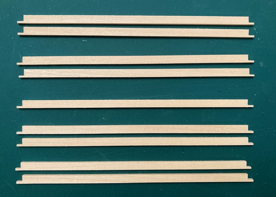 Another styrene jig was constructed to cut the 9" deep notches in the end beams. A stop was set up in my micro-miter box to the precise width of the floor and end beam blanks were cut from the 6x12 scale stripwood. The cutting jig allowed me to cut the two 9" vertical cuts for the notch, then a new, sharp #11 scalpel blade was used to carve out the wood between the two cuts, and the bottom of the notch was filed flush to the top of the scale 3" styrene strip with a small pillar file: 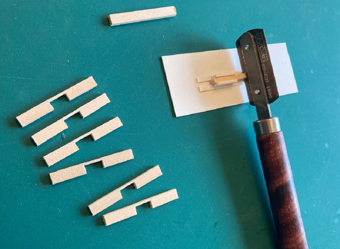 The new side sills and end beams got the Dullcote treatment, and then . . . Assembly Begins: The side sills were carefully aligned to the bottom of the floor, careful to keep the outside of the sill flush with the inside of the stake pocket cutouts and flush with the ends of the floor. The sills were tacked into position with thin ACC using some small brass wire as an applicator, then ACC run down the inside sill to floor seam. When dry, excess ACC was removed from the wood with the skinny fiber glass eraser: 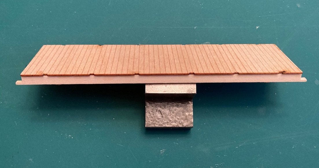 Next, the two halves of the center/intermediate sills were separated and carefully positioned per Bill's locator markings, tacked and glued with ACC, again removing excess when dry. Bolsters: The kits include a pair of ASF bolsters cast in brass. The CAD design for these pieces was done by our own Steve Guty, co-sponsor for the HOn3 kit. Bill has pre-drilled the bolster holes with a tap drill for 0-80 screws (but didn't both to tap them). As I prefer metric screws, I drilled out Bill's holes with a tap drill for 1.4 mm metric screws, then tapped them for the same. There is an annoying brass sprue from the brass casting process that attaches to the inside vertical edge of one of the L-brackets for the side sill. The instructions say to carefully remove all this brass with needle files . . . nope, that will take forever. I simply cut the sprue off flush with the outside edge of the end of the bolster casting with a jewelers saw. I then used my micro razor saw to cut into the sprue, using the inside of the L bracket for the vertical cut and the inside bottom of the bracket as a fence for the horizontal cut and the residual sprue just fell out. The L-bracket was then dressed with a small pillar file to match the other. With the frame upside down, I tried to install the bolsters between the side sills, but they didn't want to fit. No fault of Steve's design, as he drew the bolsters to precisely fit between 5" side sills, while the side sills for the kit are 6" thick. This may or may not be a problem for the On3 and HOn3 kits. So more filing of the L-brackets to remove more brass and finally they (snuggly) fit in place: 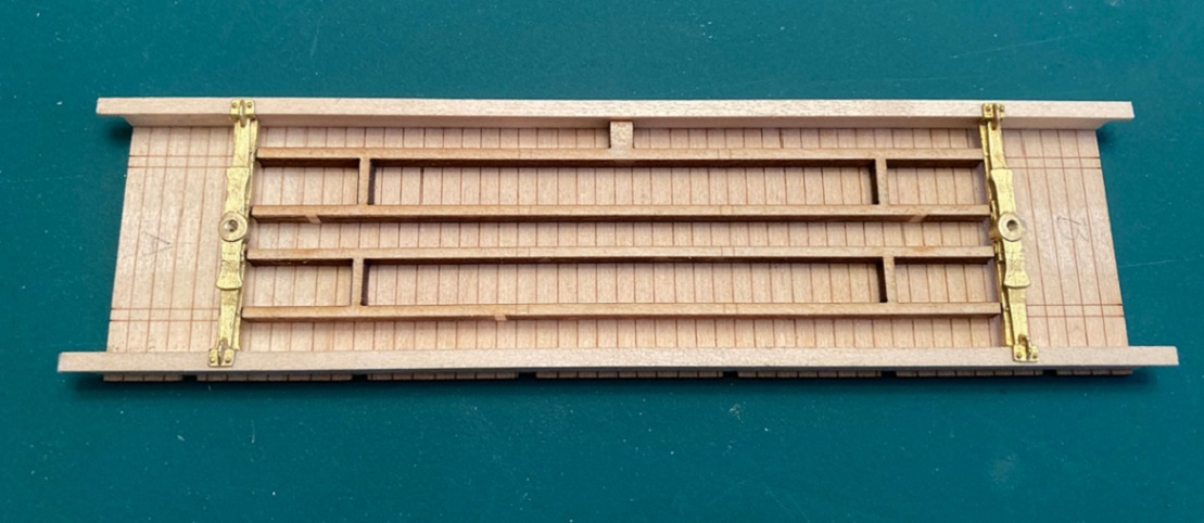 Mounting trucks and adjusting body height: The 1898 and 1902 coal cars are real "low riders". The distance from bottom of side sills to rail top was 20" on the 1898 cars and 21" on the 1902 copies. I find this "hunkered down on the trucks" look to be very appealing. But when the ASF trucks were mounted to the bolsters of my car, the car sat on the trucks about 4 scale inches too high. The major issue is the height of the truck bolsters, taller than prototype to allow mechanical assembly that is sturdy. My only solution was to use a flat mill file and file the car bolster bearing disc down flat, to the same height as the rest of the bolster center (sorry Steve!). This lowered they car by about 1.5 scale inches. So then I had to resort to filing the truck bolster bearing and the square plate below it off the top of the truck bolsters. This corrected the car height to 21 scale inches, rail head to bottom of side sills, just right! 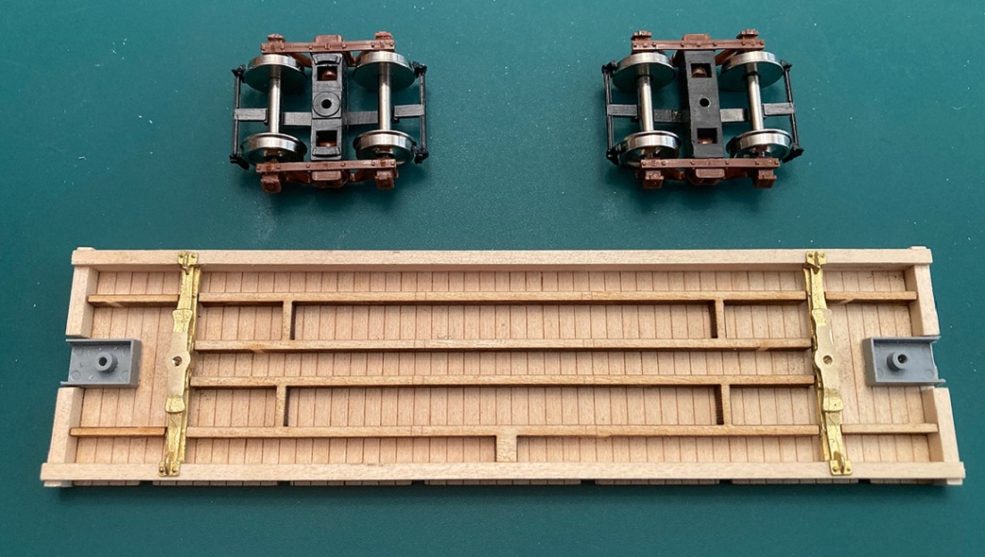 Stock truck bolster on left, modified truck bolster on the right. Note that coupler draft gear boxes have ben test fitted with double sides tape. With the bolster / truck mounting complete, I added the 4 small laser cut intermediate sill extensions from bolster to edge of floor with ACC. Then the end beams were mounted into the notches of the side sills and against the floor, tacked into place with ACC, then carefully secured with ACC. Any part of the lower side sill that protruded beyond the end beam was cut flush with the end beam. The 6"x12" end beams stick up a bit above the top of the floor. This is good, as the real ones were 6" x 11". The top of the end beams were sanded flush with the top of the floor using sand paper on a flat surface. Coupler mounting: All of Bill's kits make the same provision for couplers. A notched end beam (with or without end sheathing) with the bottom of the notch flush with the bottom of the floor and and empty space from bolster to end beam and between the intermediate sills. As all C&S freight cars had floors the same height above the rail (trust me on this), I've come up with my own system for mounting couplers: 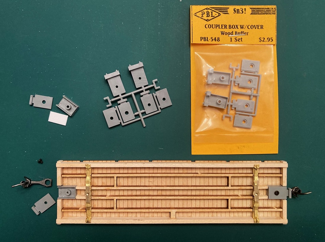 I use PBL part 548, "coupler box with covers". I use the razor saw to cut the D&RG striker block from the front of the draft gear box. Evergreen 0.030" x 0.25" strip is cut to the same length as the box and glued to the top of the box, centered. A short 1.7 mm screw is screwed into the hole in the stem of the box to cut it's own threads. I use the long cover plate with the carrier iron (to keep the coupler from drooping). The box is then glued to the underside of the floor, the front edge just a wee bit in from the outer edge of the end beam, being careful to keep the draft gear box centered (to the floor, not the notch. When dry, I insert Kadee #146 couplers (standard head, whisker couplers with long center shank) into the box, screw on the cover plate, and remount the trucks. Testing, the couplers match the same height as all my other C&S cars. Don't be concerned that the coupler head protrudes too far from the end beam. The striker block will fill that gap. Striker blocks: This is a laser cut part, again 6" thick, again with bevel on the cut surfaces. Bill has provided an etched brass striker plate to glue onto the front surface. This may be okay for the 1898 car, but for the 1902 coal car it didn't look right. I have never seen a clear photo of the 1902 coals as built, but our late friend, Doug Heitkamp, posted this photo of one of the 1902 flat cars after automatic couplers were installed: 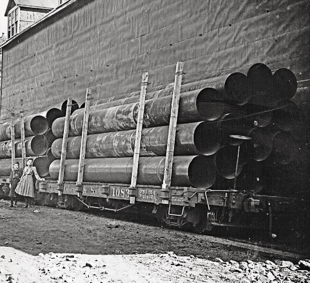 And another photo of a 1902 flat car taken about 1912: 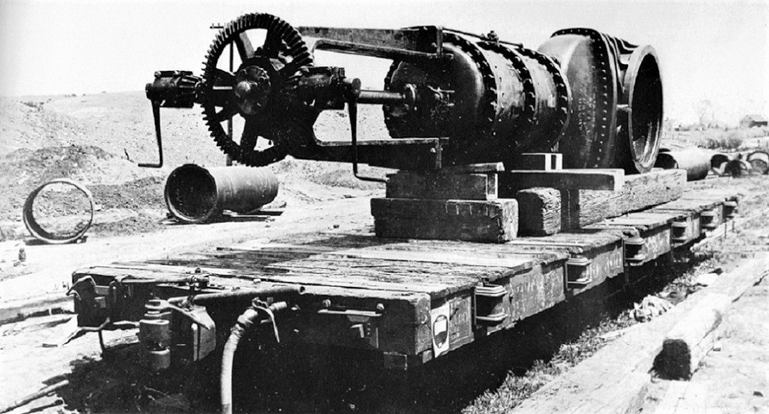 As the 1902 flat cars and coal cars left the C&S shops at the same time, I'm assuming that the end beam details are identical. The draft gear striker plate looks taller here, with the truss rod NBW below the bolt head securing the striker plate to block. As I'm still working on several of Bill's C&S boxcar kits, I have already worked out construction of the striker block in styrene, and have a large stash of precut parts: 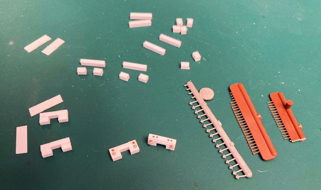 The blocks are 3 pieces of 0.080" thick styrene glued together, then sanded flush at the ends. A piece of 0.010' x 0.156" styrene is then glued over the front of the block to represent the striker plate, the opening cut out with a sharp knife, and squared up with needle files. The truss rod NBW is Grandt #93, while Tichy rivets were used--0.030" for the striker plate, 0.025" for the four bolt heads atop the block. Before attaching the blocks to the end beams, I located and drilled out a vertical 0.020" hole for the brake staff in one of them--it is much easier to do this now than after the part is attached to the car. Finally, the striker blocks were attached to the end beams, making sure that the one with the vertical hole was glued to the "B" end of the car: 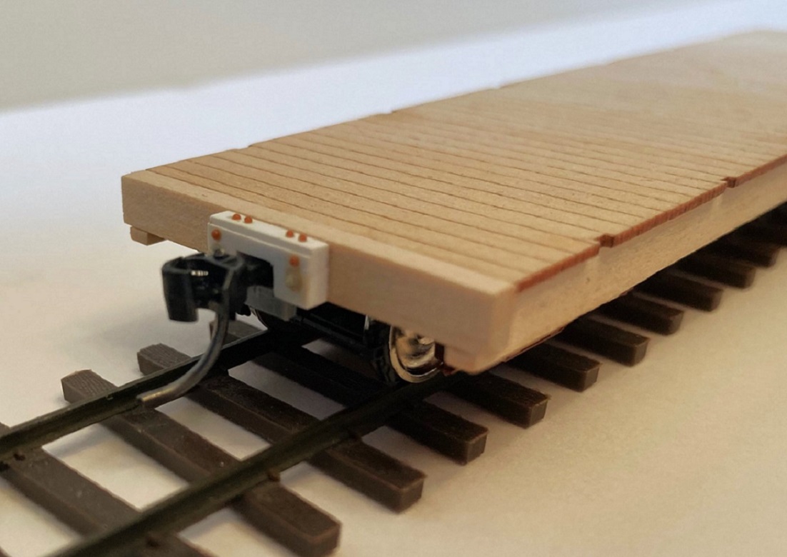 Whew! Such a long post, hope ya'll find this helpful. In the next week or so, I will finish building up the other three kits to this level of construction, so I can stain all the decks at the same time. Then, moving on with underframe detailing (plumbing / brake rigging and such) and finally the open box body and side stakes.
Jim Courtney
Poulsbo, WA |
Re: Building Leadville Designs Coal Car / Flat Car / Cinder Car Kits in C&Sn3
|
Thanks, Jim! Very informative. My cinder cars are en route.
I found some of my recent trucks have a casting issue. 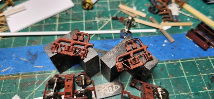 I reported this to Paul, and he is checking his stock. I have not seen these cracks on the older trucks cast in brown Delrin, but had it crop up in the new black material. Paul is working on replacements.
Keith Hayes
Leadville in Sn3 |
Re: Building Leadville Designs Coal Car / Flat Car / Cinder Car Kits in C&Sn3
|
In reply to this post by Jim Courtney
I received my cinder cars today. Thanks, Bill.
And thank you, Jim withe rhe illustrated guide to assembly. I need to serve my two kits aside so I can focus on the helix next. I am getting behind with two stock cars, a Pullman and baggage car to assemble! Thanks to all of you out there: we are keeping the NY air brake cylinders, C&S brake wheels and 5" queen posts in production!
Keith Hayes
Leadville in Sn3 |
Re: Building Leadville Designs Coal Car / Flat Car / Cinder Car Kits in C&Sn3
|
This post was updated on .
Some progress over the past week. I've been slowly building up the other three kits so that the floor/frame/trucks and couplers reach the same level of completion as the first kit, above. I've been using the same assembly sequence, with one major exception . . .
1898 St. Charles Bolsters: The cast brass bolsters in the kit represent the cast bolsters that the C&S shops purchased from American Steel & Foundry, along with the ASF arch bar trucks, for the 1902 construction of the coal cars and flat cars. The coal cars built by St. Charles in 1898 used the St. Charles double plate bolster: 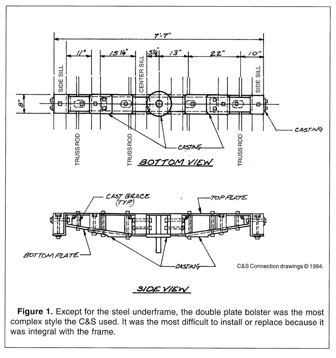 Derrell Poole drawing, published in Outdoor Railroading, 1995 As I'm building one of the four kits as an 1898 St. Charles coal car for my 1901 freight roster, I decided to build up the bolsters from styrene. To avoid having to modify my Cimarron Works St. Charles trucks, I used Mr. Micrometer to calculate the height of the needed bolster, from bottom of car floor to lower bolster bearing plate, by my estimation 0.190". I used S scale styrene 4x8 strip to extend the intermediate sills from the end of the wood sills to flush with the end of the floor. Then the end beams were added as in the last post, and the tops of the beams sanded flush with the top of the floor. The modified PBL draft gear boxes were then attached, again as above. Then more of the 4x8 strip was cut to extend the wood center sills to the draft gear boxes. A piece of S scale 8x8 was cut to fit between the two center sill extensions as a pad for mounting the truck screws. The 4x8 center sills have an actual height of 0.13". I cut styrene 0.040 x 0.125'' strip to width, over the outside edges of the center sills, as a bolster build up, bringing the central height of the bolster to 0.170". Finally, a bearing plate was cut from 0.015" strip to form a 10" square and centered over the bolster block. The entire assembly was drilled and tapped for 1.4 mm screws and the trucks were mounted. Though the entire bolster build up was only 0.185", the car height seemed right on! 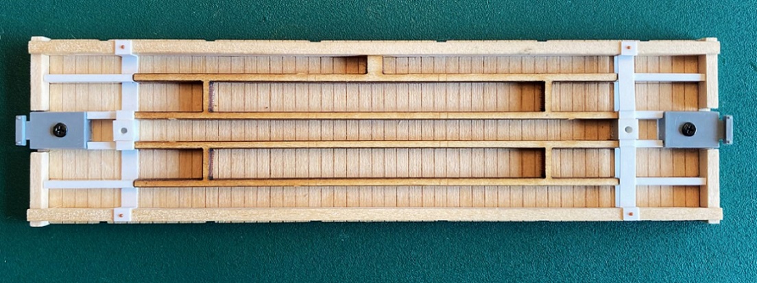 I built up the double plate bolster using 0.015 x 0.125" strip for the bottom plate, against the floor, and 0.010 x 0.125" strip for the L-bracket under the side sills (above, left). Then the bottom plate was cut to length, by trial and error, from 0.015 x 0.125" strip and attached (above, right). 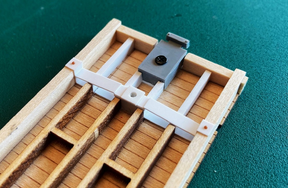 The deep side sills and mounted trucks make the center of the bolster impossible to see, so no time was spent trying to detail that part of the bolster. I did add Tichy 0.030" bolt heads to the bottom of the sill bracket. All that can really be seen on either type of bolster is the bottom of the sill bracket--the 1898 bolster had a single bolt head, while the 1902 ASF bolster had two bolt heads separated by the semicircular fin. I built up the end striker blocks and face plate with the precut parts described in the last post. I used this photo of the end of a St. Charles coal car, c1900 to detail the striker plate, one of many great photos posted on the Forum by our late friend, Doug Heitkamp: 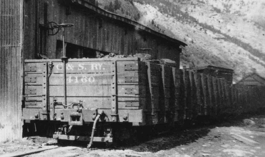 The 1898 cars did not use nuts on washers to secure the truss rods to the ends, rather the truss rod ends were about 2.5" square bolt heads--evidently, the truss rods could only be tightened with the turnbuckles. I cut the square bolt heads from 0.010 x .0.40" styrene and used Tichy 0.030" rivets above. Don't forget to drill the vertical hole for the "B" end brake staff before attaching the completed striker block/plate assembly to the ends! Once the end striker blocks were attached I decided, since I was cutting square bolt heads, to attach the vertical rectangular washers and bolt heads to the outboard of the end beams: 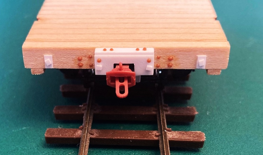 To further test the ability to use MEK to attach styrene details to the Dullcote sealed wood, I decide to add Tichy rivets for the brake hanger attachments. So far, so good. Nothing has fallen off yet! The link-n-pin couplers are O scale parts from Foot Hill Model Works. They are small logging couplers in O scale, just about right for TOTC C&S couplers. Hopefully, the next post will have all four kits up to speed, ready for weathering the deck boards and proceeding with further construction. 
Jim Courtney
Poulsbo, WA |
Re: Building Leadville Designs Coal Car / Flat Car / Cinder Car Kits in C&Sn3
|
This post was updated on .
Work this past week brought all four kits up to the same level of completion:
Frame, bolsters, trucks, end beams, couplers and striker blocks. Today I stained the decks of all four cars, the coal car decks turned out well: 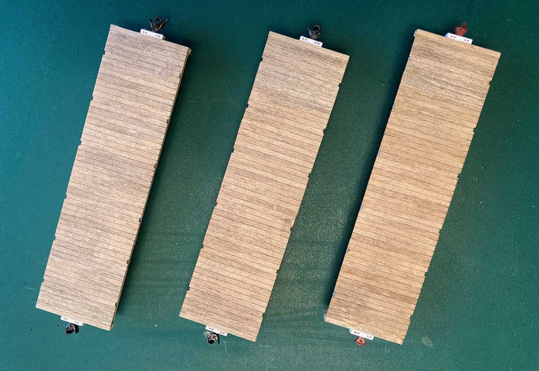 I use black and brown leather dyes in very dilute washes thinned in 70% isopropyl alcohol. I give each deck first a wash of black and then a wash of brown, to warm up the decks, so it doesn't look like bleached driftwood, Then, using a small sound brush, I re-stain random boards with black, others with brown, some with both. Happy to report no warping of the wood. But things didn't go well for the deck of the 1902 flatcar, proving the premise that "bad luck" always befalls any model building project: 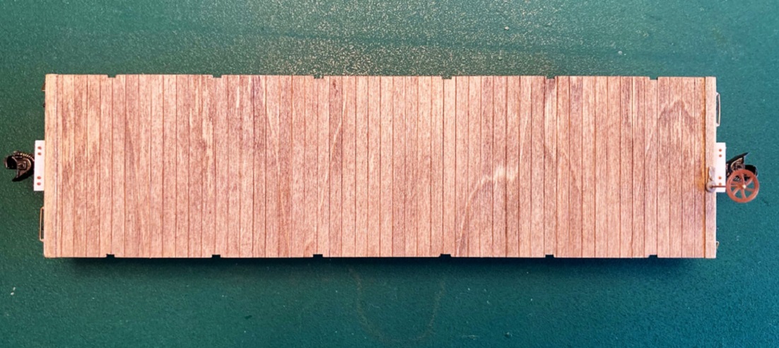 I stained this floor in an identical fashion, only to find annoying "grain swirl" appear. Only I would pick the bare cut floor with all this swirl (I really couldn't see it as bare wood) for the flat car build. I had intended this floor to be left empty, or perhaps a small partial load. But now, there is no fixing this. My 1902 flat car is destined to have its deck covered with a full load, perhaps a load of large diameter pipe, as in Doug Heitkamp's photo. Speaking of Doug's photo, I decided to go ahead with detailing the flat car end beams.  The square washers in Bill's kit are etched brass, measuring 6"x6", agreeing with Derrell Poole's plans. But Mr. Micrometer says the square truss rod washers are more like 8" square. So I used Grandt O scale castings instead. The 18" grab iron was laid out on the right of the end beam, the small 6" diagonal grab on the extreme left end of the end beam. The brake staff on the coal car did not go through the draft gear striker block, rather down through the end beam. The brake staff/wheel/ratchet and pawl are not yet glued into place. The retainer is from my parts box, the brake hanger bolt heads are Tichy 0.030" rivets. Still need to add the coupler lift rods. 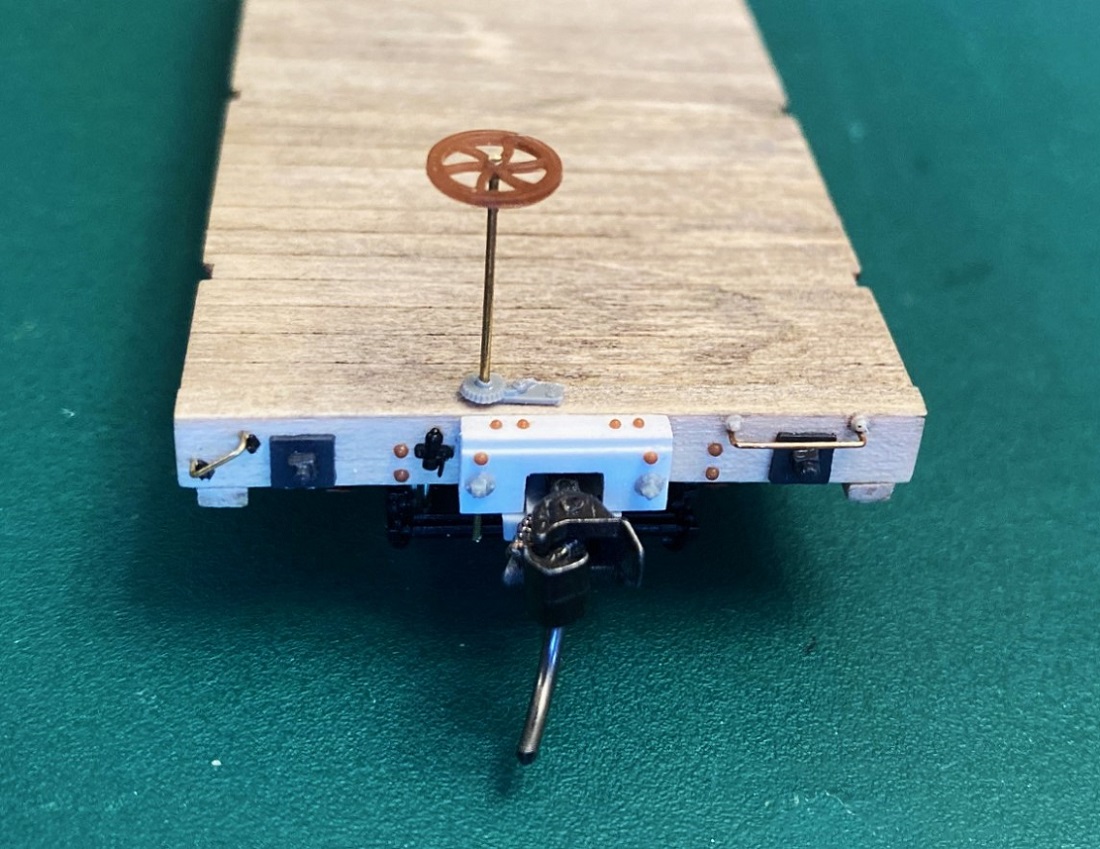 I've spent an hour this evening looking at all my collected photos of 1898 and 1902 coal cars (all grainy and out of focus). I can find no evidence that the coal cars had any grab irons on the end beams or on the side sills. I thought the mix of the little diagonal grab and the full length horizontal grab on the 1902 flat car end beam to be a curious anomaly, but then this may have been a common first decade convention for C&S flat cars: 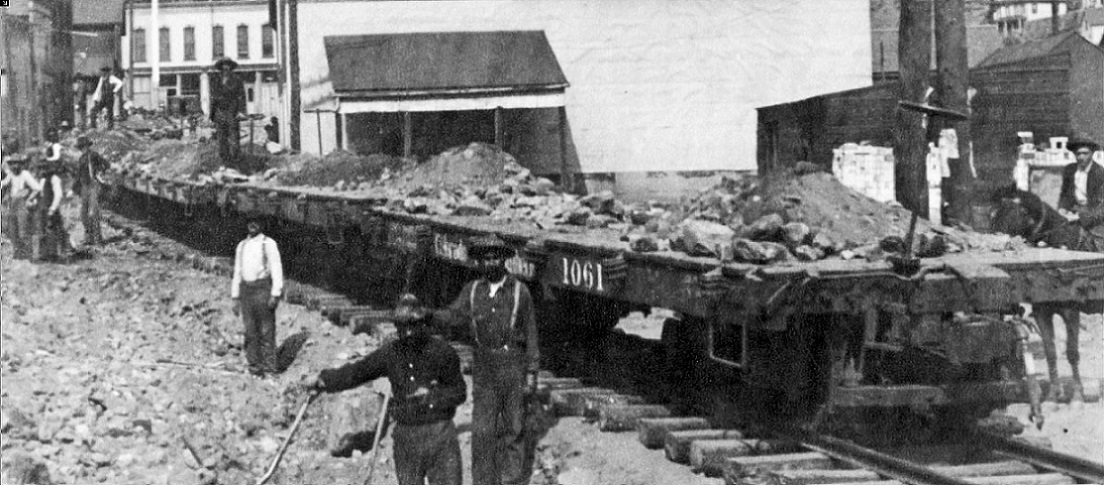 Flat car 1061 was an 1884 Peninsular flat car that has been shopped in the late 1890s or earlier in the first decade, with new straight, notched side sills. It has the same curious little 6" diagonal grab iron as the 1902 flat cars above. So, up next, finishing the end beams on the coal car bodies (square washers/nuts, braked hanger bolt heads). Then stirrups (only 2 per car). Maybe I will finally get to adding stakes to the sides and begin building up the open box bodies. 
Jim Courtney
Poulsbo, WA |
Re: Building Leadville Designs Coal Car / Flat Car / Cinder Car Kits in C&Sn3
|
Slow but steady progress on the four car build project.
Stirrups: The DL&G and subsequent C&S car shops (actually the same guys) fabricated their own unique corner stirrups for the narrow gauge freight cars. Instead of using steel strap, an iron or steel rod was used, about 1" in diameter, bent into a shallow squared U-shape. The left vertical was flattened at the top and bolted to the side of the car, while the right vertical was flattened on the top and then bent back 90-degrees and bolted to the bottom of the side sills. Doug Heitkamp's flat car photo is a good illustration of this type of stirrup, in common use by the DL&G/UPD&G/C&S shops until the 1907 building program began:  Both the 1902 coal cars and flat cars used these stirrups, 2 per car on the right end of each side. The 1898 coal cars, built by St. Charles, also used a steel rod for the stirrups, but both verticals were flattened and bolted to the side of the sill, as illustrated in another photo that Doug shared with us: 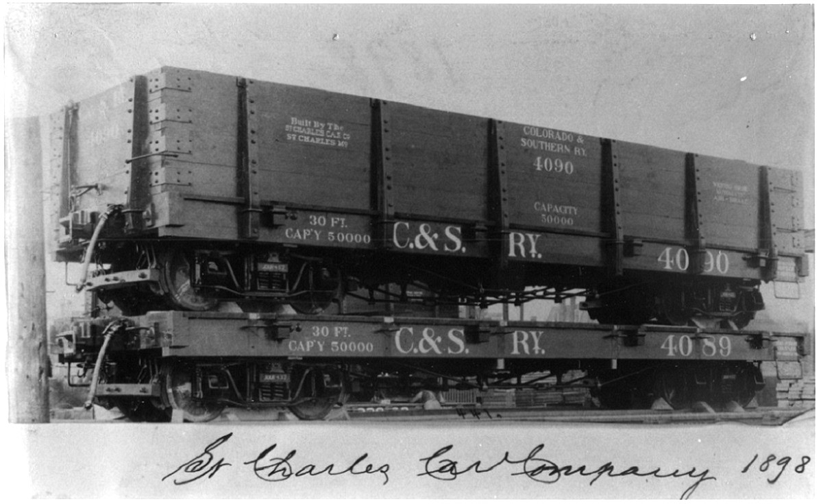 To make S-scale stirrups I use the following procedure: 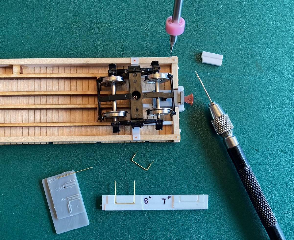 I use 0.015" brass wire, bending up square "U"s on a grab iron bending tool on 21" centers. I constructed a top bending jig from styrene, place the stirrup in the jig and bend the tops back about 45 degrees. I use a bit of 0.010" styrene glued to a thicker piece to make a scribing fence, and using my micro-awl (sewing needle in a pin vise), I scribe a line parallel to the outside of the side sill just 0.010" in. I locate the position of the holes for mounting the stirrup and drill into the wood sill at a 45 degree angle, first with a number 80 bit, then enlarging it with a 78 bit. When the two trimmed ends of the brass stirrup are inserted into the holes and seated to where the bend reaches the bottom of the sill, the wire is glued in place with ACC. The wire stirrup is then carefully straightened so it is vertical relative to the bottom of the sill: 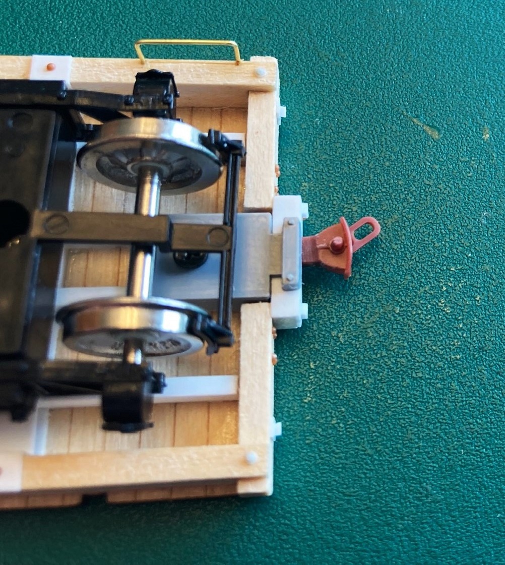 The outside of the brass wire ends up within about 0.003" from the edge of the side sill. I use the top of a PBL or Berlyn cast stirrup for the vertical attachment to the side of the sill, Evergreen strip for the fastener on the bottom of the sill: 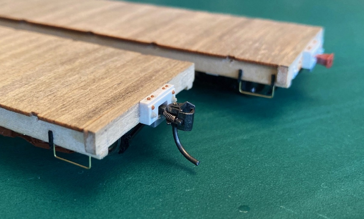 Stakes: There's good news and bad new about the stakes in the kit. Good news, Bill Meredith has included two complete sets of 3-D printed stakes in the kit for modeling different cars. Most folks will use the straight stakes with square cross section (4x4) to model the replacement stakes applied when the 1902 cars were refurbished for all of the Climax mill expansion business in the early 1930s. Coal car 4360 is a good example: 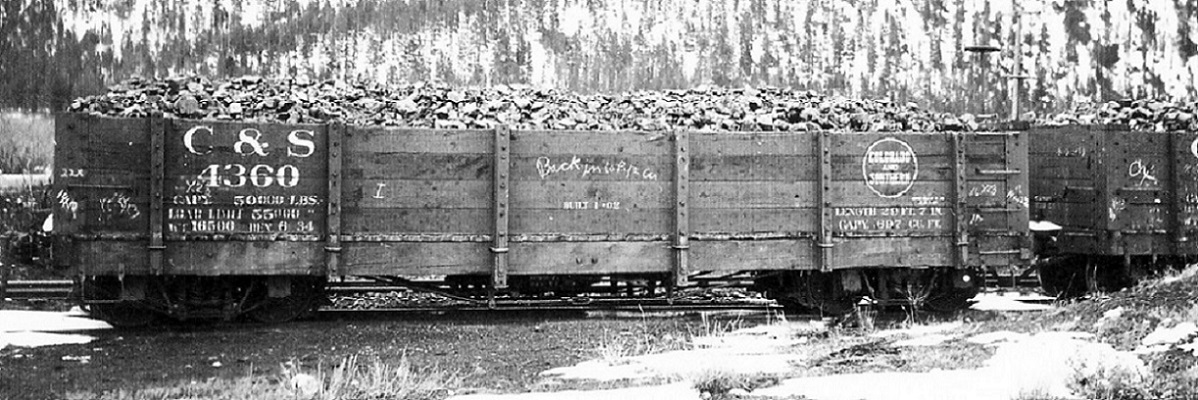 Also included is a complete set of stakes for the 1898 St. Charles coal cars, including end stakes for the as built versions. The St. Charles stakes (as noted in the builder's photo above) had a square cross section at the bottom, but above the level of the top of the deck, they tapered toward the top. The bad news is that Bill neglected to provide the original 1902 C&S stakes. They were similar to the St. Charles stakes, but were fully tapered from bottom to top. Of course, half of this project is c1909 coal cars of this type. Back in 2016 (eight years ago!  ), when we first began discussing the building of these cars, Mike McKenzie designed Shapeways prints for all three types of stakes. I have a large stash of the 1902 original stakes and decided to use them for accuracy's sake. Up until the Shapeways bankruptcy last month, Mike offered all three types of stakes, in all three scales, in his Shapeways shop. Perhaps we need to create a "C&S 3-D Printing Consortium" to get all of the neat parts that Keith and Mike and others have designed back in production--discussion best left to another, new thread. ), when we first began discussing the building of these cars, Mike McKenzie designed Shapeways prints for all three types of stakes. I have a large stash of the 1902 original stakes and decided to use them for accuracy's sake. Up until the Shapeways bankruptcy last month, Mike offered all three types of stakes, in all three scales, in his Shapeways shop. Perhaps we need to create a "C&S 3-D Printing Consortium" to get all of the neat parts that Keith and Mike and others have designed back in production--discussion best left to another, new thread.
Mike's stakes have mounting pins printed into them. I worked out that to accurately mount the stakes vertically on the side sills, holes needed to be drilled 0.030" below the bottom of the deck and centered in the stake cut outs on the floor piece: 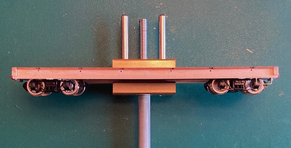 Another neat tool is my "Mini-bench vise": https://micromark.com/products/brass-mini-vise-1-1-2-inch-capacity?keyword=83441 I could carefully clamp the entire care frame in the vise, and it was heavy enough that it didn't move while marking and drilling. I used my micro-awl to locate drilling points, drilled first with a 76 drill then enlarged the holes to 0.031" with a 68 bit. Mike's stakes, after cleaning with Bestine, have a translucent/milky color and details are hard to see. I primed all the stakes with Tamiya Fine Grey primer, to make sure I didn't accidentally attach a stake that suffered from congenital malformations--all turned out fine. The stakes are a snug press fit. I squared each one up with a small machinist's square and used ACC to attach them. I then added the final details to the end beams and the side sills, including bolt heads for the bolster and air cylinder mounts: 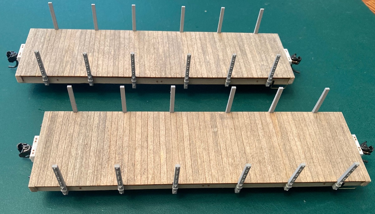 The mounting of Mike's stakes turned out so well that I decided to use his 1898 St. Charles tapered stakes as well. I will be saving Bill Meredith's printed a stakes for another project. The 1898 car has also had the St. Charles accessory stake pockets applied using San Juan/Grandt S scale single U-bolt stake pockets, located per the plans: 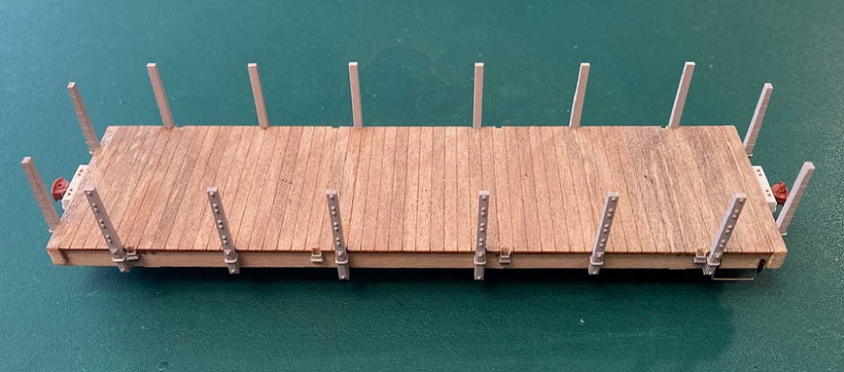 The end stakes on the 1898 car have not been glued into place yet, will save that until the side boards are installed. The 1902 Flat Car: The kit includes some beautiful 3-D printed stake pockets, actually correct for this car, a first in all scales. But, they are tedious to work with. I used a PBL "very fine" sprue nipper to carefully remove them from the printed stems. I again used my "mini-vise" to hold the car while positioning the individual pockets: 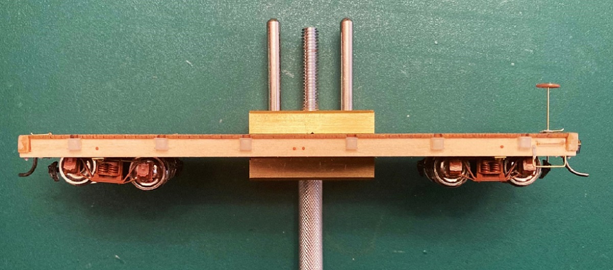 MEK does nothing to the printed resin, but it did make the Dullcote layer on the side sills tacky, so the little stake pockets would stay still for a minute after they were positioned. Then some very thin wire was used to apply ACC to the inside of each stake pocket, from the bottom, to secure them. After the remaining side sill and end beam details were applied, the flat car is pretty much complete from the bottom of the side sills, up: 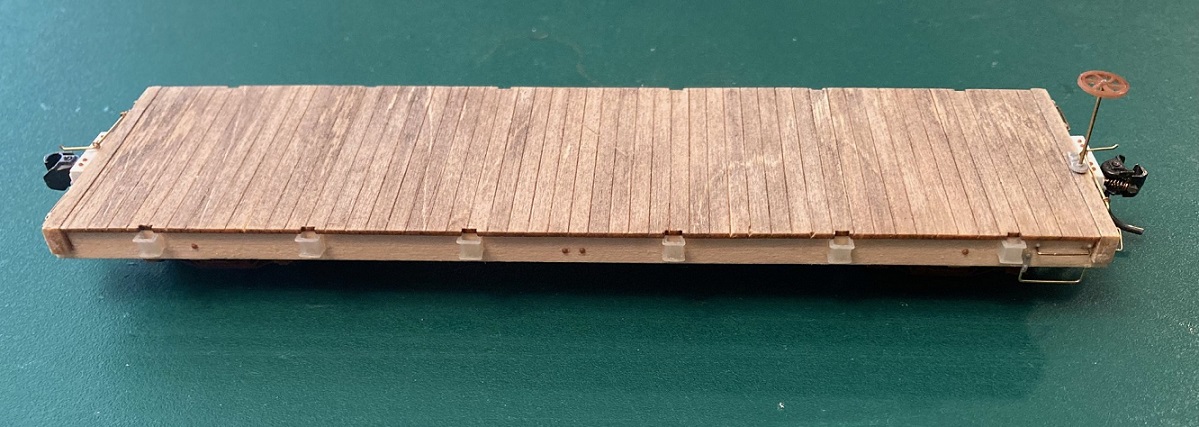 This week I'm working on the wood sides of the three coal cars and will turn the flat car upside down and start the underframe detailing . . .
Jim Courtney
Poulsbo, WA |
Re: Building Leadville Designs Coal Car / Flat Car / Cinder Car Kits in C&Sn3
|
Wow, it's been 3 weeks since I last posted . . .
 I had hoped to further along in this project by now, but, hey, life got in the way. Sides: Before tackling the sides, there was one chore that had to be done. Drilling holes in the floor for the side tie down bars--those little folded, inverted U-shaped straps on the top side board connecting to a rod that ran down the inside of each side wall, through the floor and side sill and anchored with a NBW on the bottom of the side sill. The rods were 4" from the nearest stake. On the 1898 coal car they were always toward the car end from the adjacent stake. On the 1902 cars they were all toward the car center relative to the adjacent stake. I located and drilled out the holes with a #78 bit. The sides in the kit are nicely engraved with four side boards (four 2x10s) on inside and out, with location engravings for the stakes on the outside. I wasn't happy with the six laser cut holes for the post-USSA grab irons and NBW, so tried filling them with plastic wood and sanded them smooth. After staining as I did for the floors, the results weren't satisfactory--the plastic wood took the stain differently, so instead of a vertical row of 6 holes, there was a vertical row of 6 dots. And the grain pattern on several sides crossed multiple boards. So, I got out my stash of Kappler 2x10 strip wood, added grain with a wire brush and stained them randomly as I did the floors. When dry, I cut them into 6" strips and chose the best looking boards for the interior of the walls: 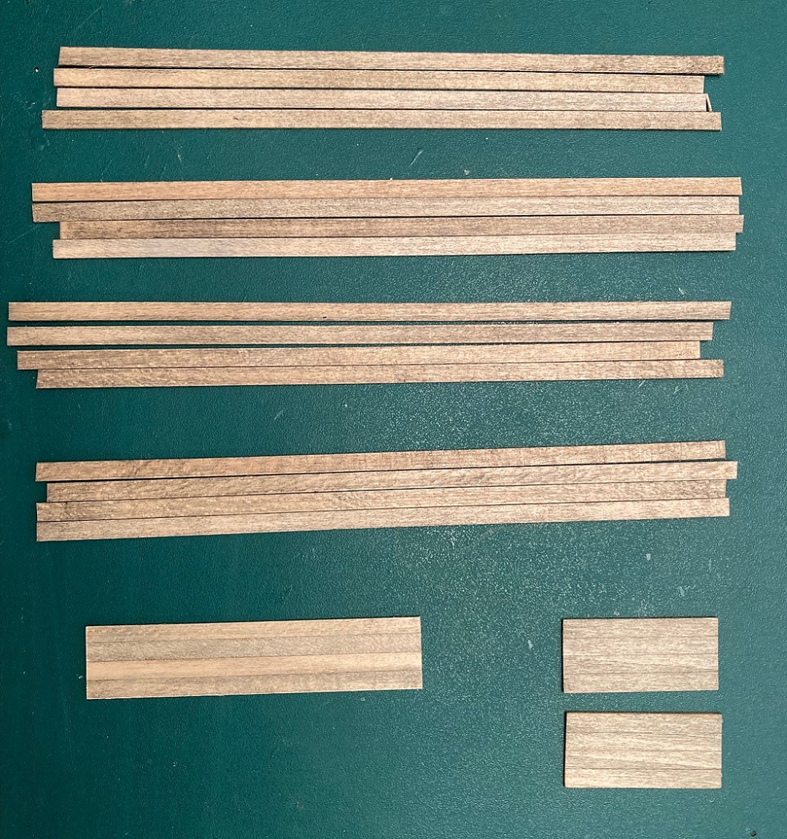 I also stained the ends from the kit. I very carefully used wood glue with 0.010" wire as an applicator to glue the four side boards for each side on edge. I used left over strip to make a wall section to cut ends if I need them. Before attaching the sides I needed to seal the outside of the wood walls, but instead of Dullcote, I used Tamiya fine grey primer, so I could examine the exterior surface for glue oozes or smears-sure enough, there they were! More sanding ensued. Test fitting the sides, they were taller than Mike McKenzie's stakes--Mike's stakes are the right length, but the thickness of the floor is about a scale inch thicker than the prototype. So, I set out to sand the bottom board of each side down about 0.015-0.020". I used my NWSL "True Sander" with the 90 degree side of a large drafting triangle as a mitre gauge, to keep the bottom, parallel to the top: 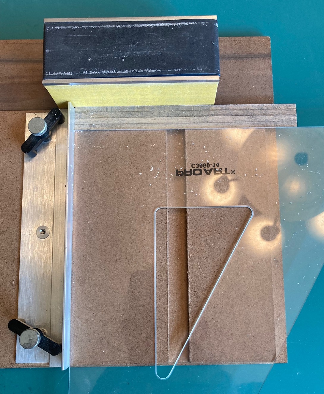 When the sides were test fitted to the floor and stakes and were the same height as the stakes, I measured the total floor length over the end beams with my micrometer and cut the sides a wee bit oversized. I then again used the True Sander to square up the sides and sand the ends to exactly the car floor length (each car varied a bit). To attach the sides, using my loops, I carefully positioned each side so that both ends were flush with the end beams and clamped it to a stake to keep it in position: 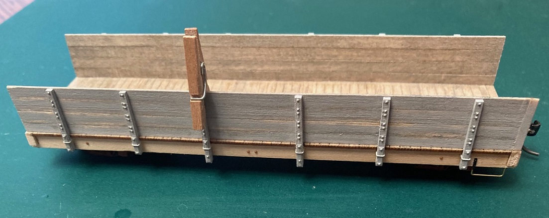 For clamps, I used "Doll House Clothes Pins"--I bought a bag at Michael's for a few bucks. They don't have teeth that might mar the wood surface. Note that I followed the rule of "measure once and cut twice" on the clamped side wall, one side wall too short and had to add some 2x filler to the end. Fortunately, this is a 1902 car and the filler will be covered by the corner iron. With the sides clamped in place, I first ran thin ACC to the joint between the bottom of the side and the floor, using a piece of thin wire as and applicator, keeping the bottom of the side pushed against the bottom of the stakes. When this joint was dry, I used clothes pins at each stake to hold the sides approximated, and ran thin ACC along the joint. The end pieces were weird--each end space was slightly different in width between the side interiors. Must be from how I located the side sills in the first step. On the 1899 car, the ends in the kit were too narrow, so I cut ends to fit from my extra side wall. On one of the 1902 cars the kit ends fit perfectly, while the other requires a bit of 2x2 filler on one end, sanded down. I positioned the end walls so that the outside edge of the bottom was flush with the end beam and glued the end bottom to the floor first. I then pulled the tops of the sides to approximate them to the side edges of the ends and ACC'd them into place. Finally, the end stakes of the 1898 car were glued into place. This completed the basic wood build up of the kits. To celebrate this construction milestone, I masked off the interiors of the coal cars, as well as the top of the flat car floor, and gave each car a couple of light coats of fine grey primer: 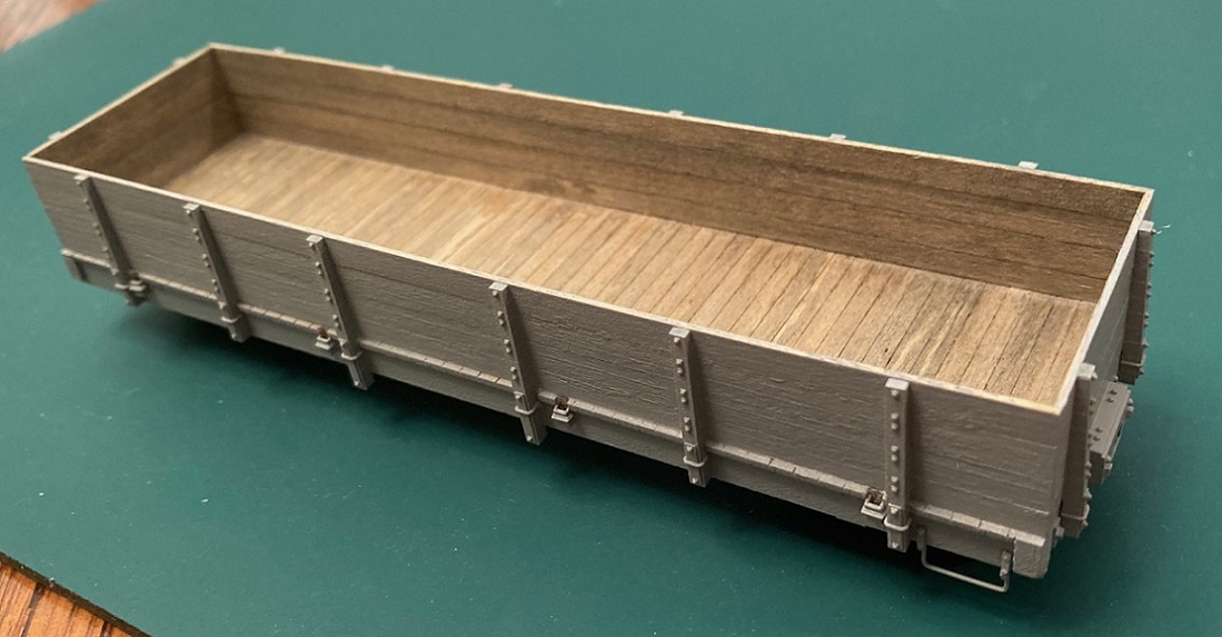 1898 St Charles coal car 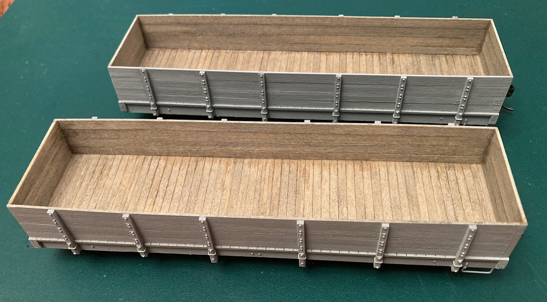 1902 Coal Cars 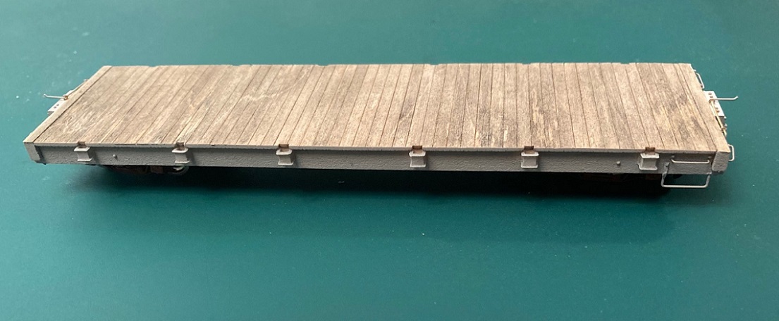 1902 Flat Car Corner Irons and Grab Irons: The corner irons for each variation that are included with the kit are very thin etched brass, with finely rendered tiny bolt heads. However, there are no fold lines on the back! The instructions say to "grasp the corner irons in your pliers, as close to the middle as possible, then bend to a 90 degree angle". Sorta reduces the odds of producing identical corner irons. And the one piece corner irons for the 1902 car have three etched holes for the USSA grab irons, making them unusable for my purposes. So, I used Grandt/San Juan S scale "D&RG High-side Gon" corner irons for the two 1902 cars. I set a stop on my mini-miter box and cut them to length so the little bolt heads would line up with the side board seams. The outside irons were attached to the corners with MEK. This bonded the styrene to the primer layer of the side walls very cleanly. I repainted the interior corner irons for the 1902 cars a dark rusty brown. These were installed with MEK was well, letting the MEK flow into the wood grain near the edges, so the paint wouldn't run. The 1902 coal cars originally had just 8 grab irons, a pair on each end and a pair on each side, located at the right end over the stirrups. Typical of C&S cars, all grabs were 21". I installed the grabs from my best guess looking at old grainy photos (see pictures below). The 1898 car is much more intimidating. There are 32 individual corner irons to apply, 4 at each corner, inside and out. And to complicate things, the prototype corner irons didn't bend at the middle--the sides were longer than the ends. My first thought was to scribe fold lines with my razor saw. I set up the min-miter box based on the length of the side of the corner iron and tried to cut shallow fold lines into the brass. Didn't work--I either made cuts too shallow, so that the piece didn't fold square, or I cut too deeply so that the part broke as I tried to bend it. After an hour and a half, I had produced only three corner irons that seemed reasonably identical. I also tried to use a bending jig of 0.25 x 0.25' styrene, with strips of 0.010' styrene attached at a right angle to create a shallow trough to locate the corner iron, then bend it over the edge of the square styrene stock. I could never get a sharp crease this way, and the bent portioned often ended up not square to the other. I have a tool ("The Bug") for bending etchings, but could not figure out a ways to make a stop, so that the bend occurred at the same place, every time. If any of you "master metal benders" out there have a tip, please share. Since I seem congenitally unable to squarely bend shim brass, I sought other solutions for the 1898 corner irons, as shown in the builder's photo:  I could build up the corner irons from 0.010" styrene strip, only 64 cut pieces to apply. And the Tichey rivets required for the bolt heads would be 8 per corner iron x 32 = 256 rivets to apply. Nope. I then recalled that Mike McKenzie had attempted Shapeways prints of the 1898 corner irons. When Shapeways finally accepted his design, he briefly offered them on his Shapeways store. I (forever the optimist) ordered enough for eight cars. But the final prints were a disappointment, as the bolt head detail didn't print on about half of the pieces, usually on the ends, sometimes on the sides. Further, there was a fuzzy artifact often connecting pairs of bolt heads. Mike abandoned the Shapeways project in favor of etched brass corner iron sets that he produced. While I couldn't find my McKenzie etched corner irons from 5 years ago, I did find my stash of printed corner irons. I picked through them and thought I had enough decent prints for at least two, maybe three cars. I primed them, used my fiberglass eraser to clean off any fuzz and applied them: 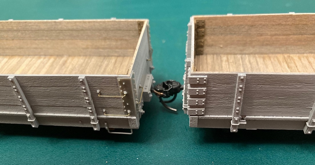 1902 coal car on the left, 1898 coal car with corner irons on right I pre-painted the interior corner irons as I did on the 1902 coal cars before applying them with ACC. Yes, the printed corner irons are quite thick, about one scale-inch. But, the sides are square relative to the ends, the corners are square and fit snuggly over / into the corners, and each corner iron is identical to the others, inside and out. The 1898 cars had an odd grab iron on the car ends, bolted to an end stake, with a width to the edge of the car side, then bent back and bolted to the car side with a single bolt. This arrangement made the grabs droop at the corners over time:  These grabs were finicky to bend, but I eventually got four made and installed. The side grabs are 21" grabs applied per the builders photo above. This is how the ends of the two types of cars came out: 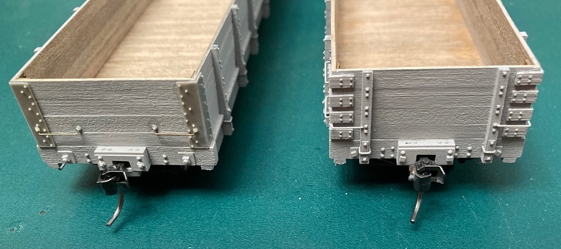 1902 coal car on left, 1898 coal car on the right And here is an end view of the 1898 car, with corner irons and side grabs in place: 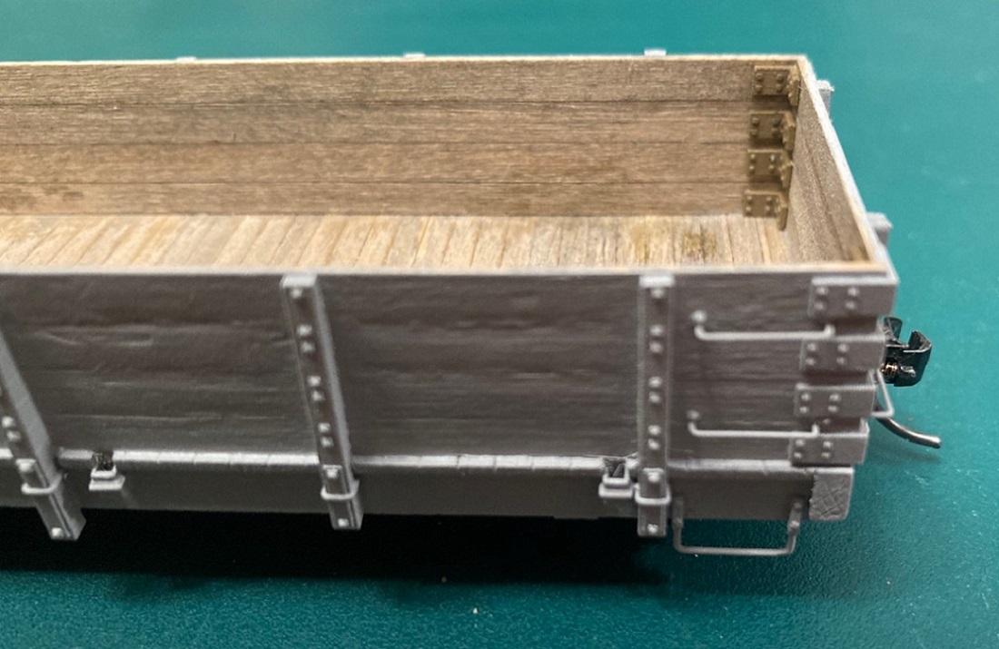 ______________________________________ So, that's where things stand as of tonight. This week I'll try to finish the body detailing with retainers and coupler lift levers, then on to the underside. I'm pleased with how the stained wood interiors have turned out, the whole point of wanting wood kits for these cars. I could probably build the cars faster and cleaner with styrene, but it's hard to make styrene look like weathered wood. I'm not real happy with the exterior finish on the cars though. I keep trying to remove glue smears that I still find after priming, and have actually scratched too far into the wood on one car. If I were to build one of the kits for a post--USSA version of a 1902 coal car, for my 1924 roster, they'd look like these guys:  I would try to use the laser cut sides in the kit, as the exterior surface is much cleaner than my glued 2x10 sides. If the interior, after staining had too much grain pattern, I'd likely just hide it with a load. I'd likely still use the Grandt corner irons though. Let's see if I can post again before October . . . 
Jim Courtney
Poulsbo, WA |
Re: Building Leadville Designs Coal Car / Flat Car / Cinder Car Kits in C&Sn3
|
I'm building both the LD cinder car and the 1898/1902 coal. I had meant to do one at a time but went ahead and jumped into the coal car after making a few mistakes (or wrong turns?) on the cinder car. Train lines can be intimidating, one of those steps that require more forethought...
I always pre-stain and quite often pre-paint subassemblies, always too anxious and hasty in my modelbuilding. Sometimes I bounce around the instructions to skip steps I may be less comfortable with, but am enjoying the builds with a ways to go. Bill's done a great job with these kits, but there are occasional gaps to fill. If I understand it right, some of the laser holes on the cinder car side frame represent stake pocket bolt holes left over from the rebuild. Additional research into the prototype is always helpful and fun, but I haven't seen any photos of the cinder car. I have Poole's drawings so they've helped, along with the photos of Jim Finnell's build. These photos were taken with my phone and aren't great but as always are unforgiving in their honesty... 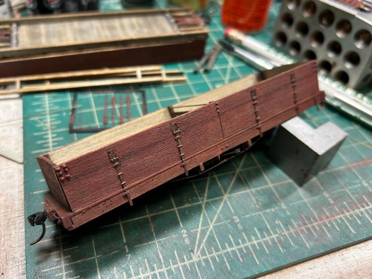 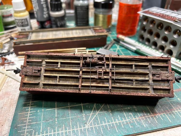 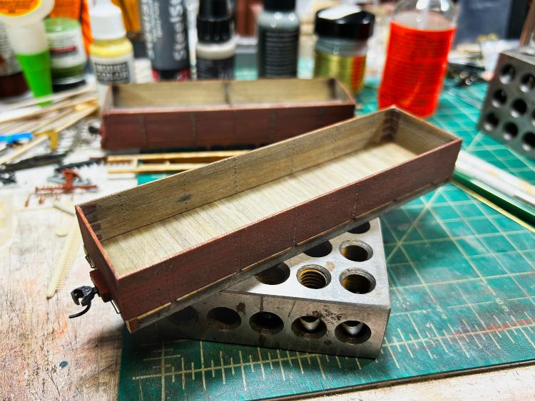 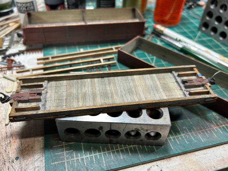 They'll be lettered for my freelanced road, so if I venture off prototype a touch I'm ok with that. One of the bolsters from the cinder car has an off center hole for the truck screw which I have to fix. I'll be using the CVP trucks but discovered some of the ones I have were poorly cast. I talked to Paul at the Pittsburgh convention and he said he'll replace them. Will post more photos when finished or need help. Mike McKenzie |
Re: Building Leadville Designs Coal Car / Flat Car / Cinder Car Kits in C&Sn3
|
Mike, Paul at PVC seems to have a pressure issue with his injection-molded side frames. I found all mine were bad and await new castings.
Keith Hayes
Leadville in Sn3 |
Re: Building Leadville Designs Coal Car / Flat Car / Cinder Car Kits in C&Sn3
|
Just learned that Paul Vaughn, owner of PVC, passed away last Wednesday before Thanksgiving.
His website is still there but shuttered, whether someone will buy the company and continue to provide his kits, trucks and parts is unknown. R.I.P Paul.
Jim Courtney
Poulsbo, WA |
«
Return to C&Sng Discussion Forum
|
1 view|%1 views
| Free forum by Nabble | Edit this page |

